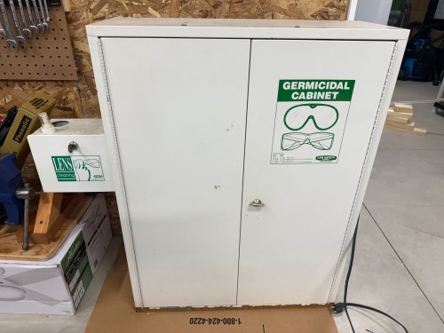
I’ve wanted some type of cabinet in my workshop for PPE and earlier this year I saw a cool cabinet that I thought might be perfect. Fast forward to the new house, the wall, and a new shop (post coming soon), so when I saw the Facebook Marketplace listing again I jumped on it.
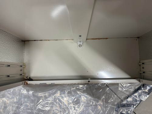
Aren’t the graphics great on those green stickers? I only paid $25 for this Sellstrom Model 2000 Germicidal Cabinet. A new one is currently 51% off on Amazon, which brings it down to $599 and replacement UV light bulbs cost over $100! This unit had some rust, like it had been sitting in a puddle, but otherwise it barely seemed used. The light bulb still works and so does the timer pictured below, which can be set to run for up to 5 minutes. You can also see the UV light bulb on inside the cabinet, through that tiny window.
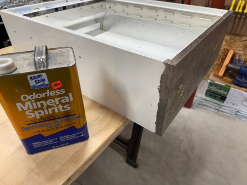
I used a razor blade to scrape as much of the rust off as I could and then used a sanding block. I cleaned the areas with mineral spirits and masked them off with painter’s tape. The bare metal got a coat of rusty metal primer.
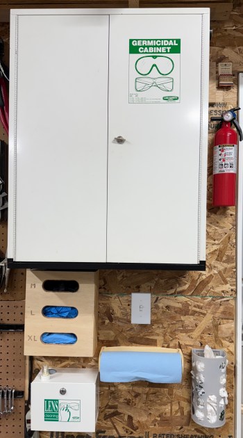
The few inside corners were painted with a non-matching white, which nobody will see. I painted the bottom exterior area with some black, which turned out great. I hung the cabinet near the door and surrounded it with my glove dispenser and other safety stuff.
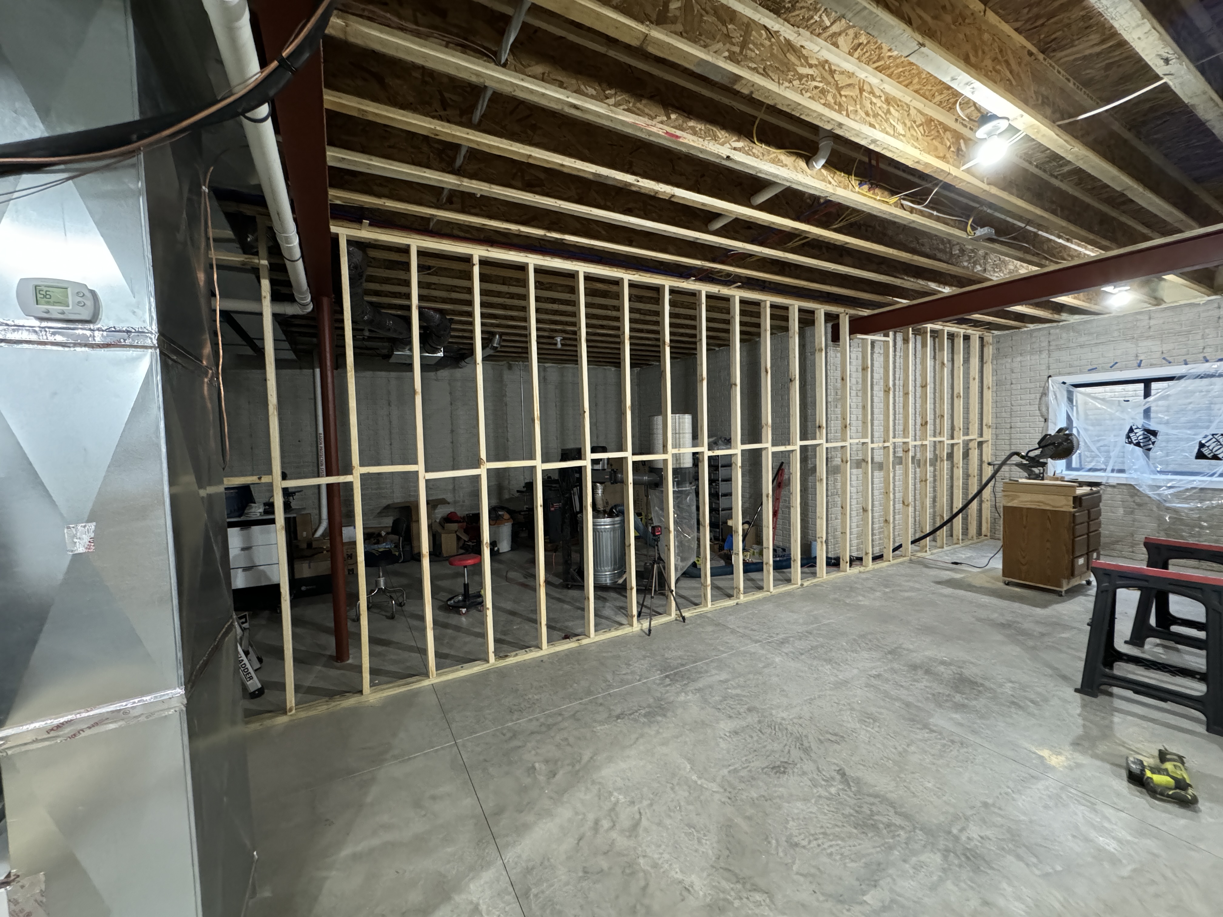
It’s been a busy few weeks packing and moving to the new house. Actually, it’s been a busy year! Building a 40 foot wall before being fully unpacked is a great idea, right? My dad was up for it, so of course I was. I’d never build a wall before, so framing was a fun challenge. This new project meant buying a couple of new tools, which I always love.
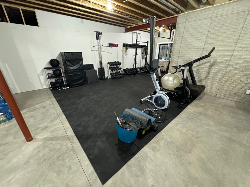
We’re very excited about this new gym area inside the house. No more garage gym for us, which was brutal in the Michigan summers and winters. There is still some organizing to do as we figure out how we use space. The wall isn’t actually finished yet either.
After I finish paneling this area I can get started on the other side of the wall. I picked up 1/2″ OSB for the shop’s wall material, to make it easy to screw small items in anywhere I want. You can’t beat $16 a sheet. Check out this cool storage space for sheet goods I gained by having the wall follow the floor joist.
I’m excited to get this mess of a shop organized, especially with all of my wood and large clamps at the other side of the basement for temporary storage. It’s going to be awesome.
After making coasters to go with my desk, I had the idea to make some as gifts for my Automattic team members, since we had a meetup coming up. Brandi also wanted to make a couple for a gift, so she helped a lot. Unfortunately I didn’t take many pictures during the process.
I’ve been wanting to try box joints for years and had saved several plans to build a jig. A couple of months ago I saw Katz Moses Tools was releasing a box joint jig and I jumped on it because their video made it look so good. It was still a pre-order at the time and the web site said it could take 3-4 weeks, but mine was delivered in a week. Assembling the jig was a piece of cake.
I was very impressed by how snug the runner fit in my table saw’s miter slot. After a few pushes back and forth it wore in and then I added paste wax to make it slide like butta! I grab some scraps and my dado stack for a quick test.
The jig is easy to use and with some quick adjustments I’ll be able to dial in a better fit. My next project will be a monitor riser for my desk so I’m looking forward to doing some walnut box joints.
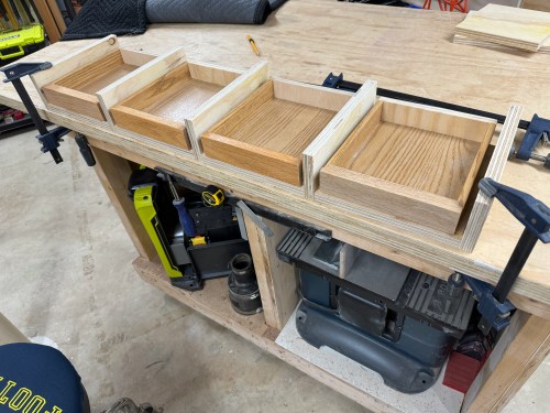
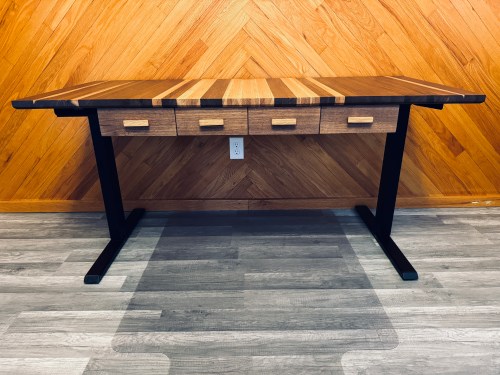
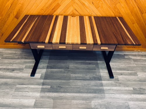
With our new house having a big walk-in closet we won’t need dressers, so we’ll be selling our bedroom set, which meant it was a good time for new nightstands. Here’s a photo dump of the build.
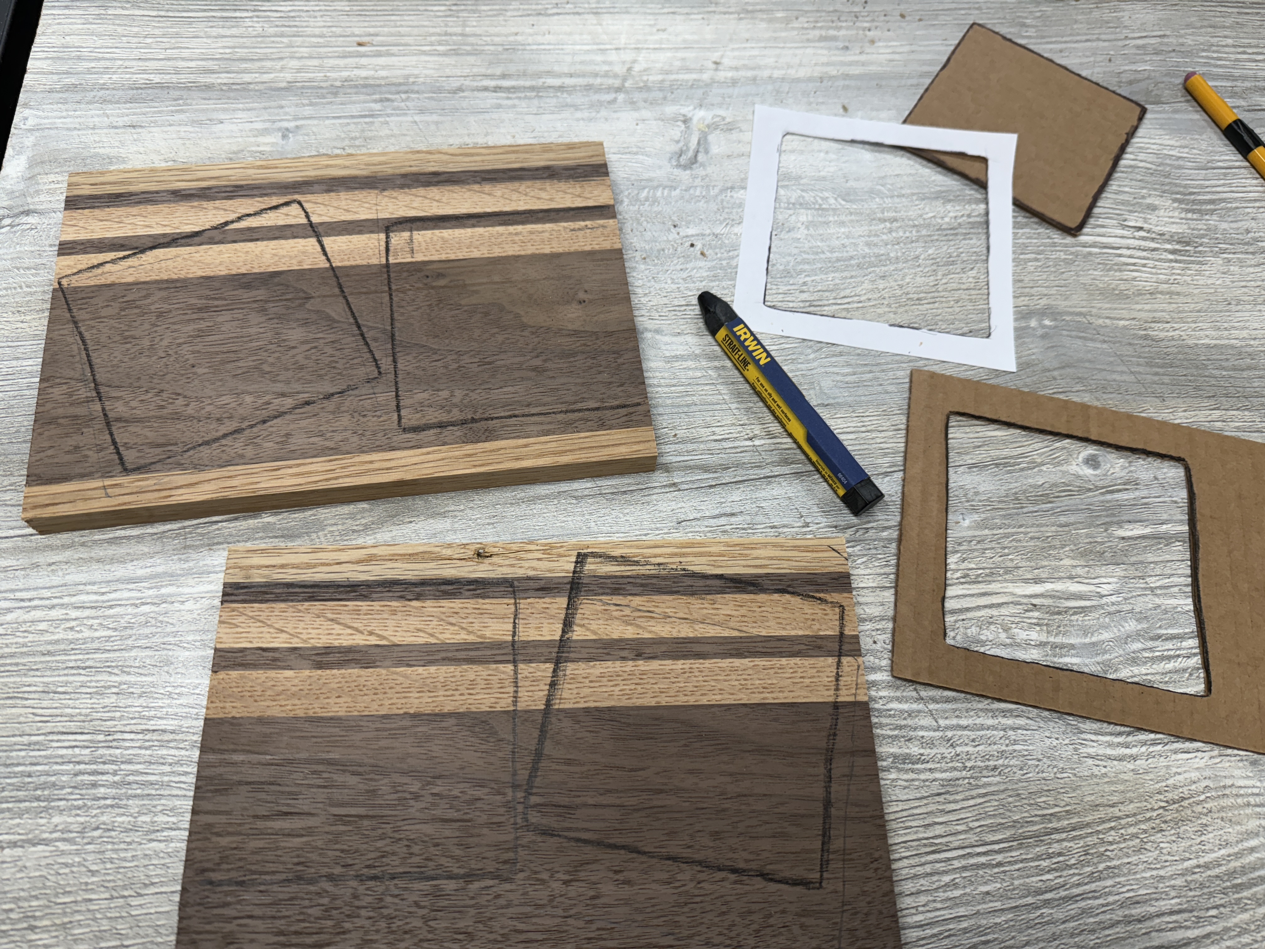
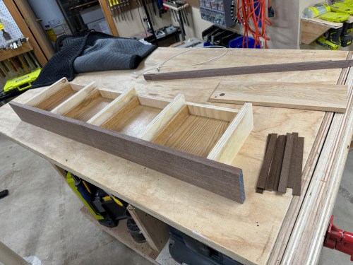
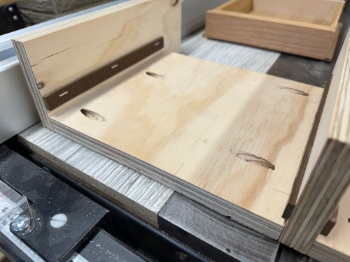
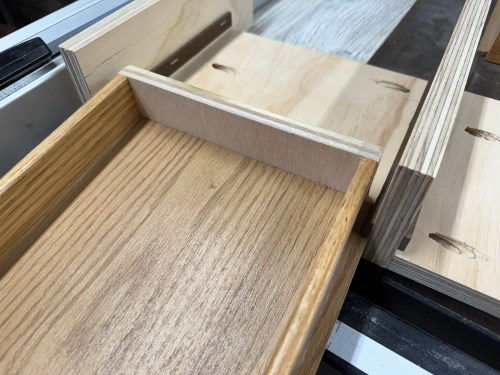
These will be floating on the wall in the new house, with about five inches of space under them. I did a lot of things in this build I’ve never tried before, so I learned a lot. I love how the decorative grooves turned out on the drawer fronts, which was inspired by something Michael Alm did on his kitchen cupboards. The oak handles were made with inspiration from a couple we liked on Etsy (1 & 2).
I can’t wait to get moved in this summer and mount these on the wall!
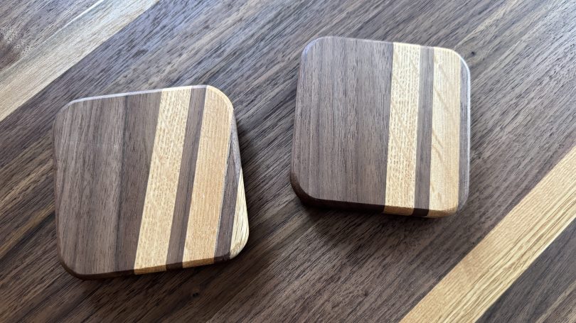
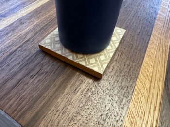
I’m loving my new desk. There are a couple of needed improvements though. First, I always have a water bottle, coffee, pop, or several on my desk when working, so I had grabbed this coaster from the living room. It bugged me all week.
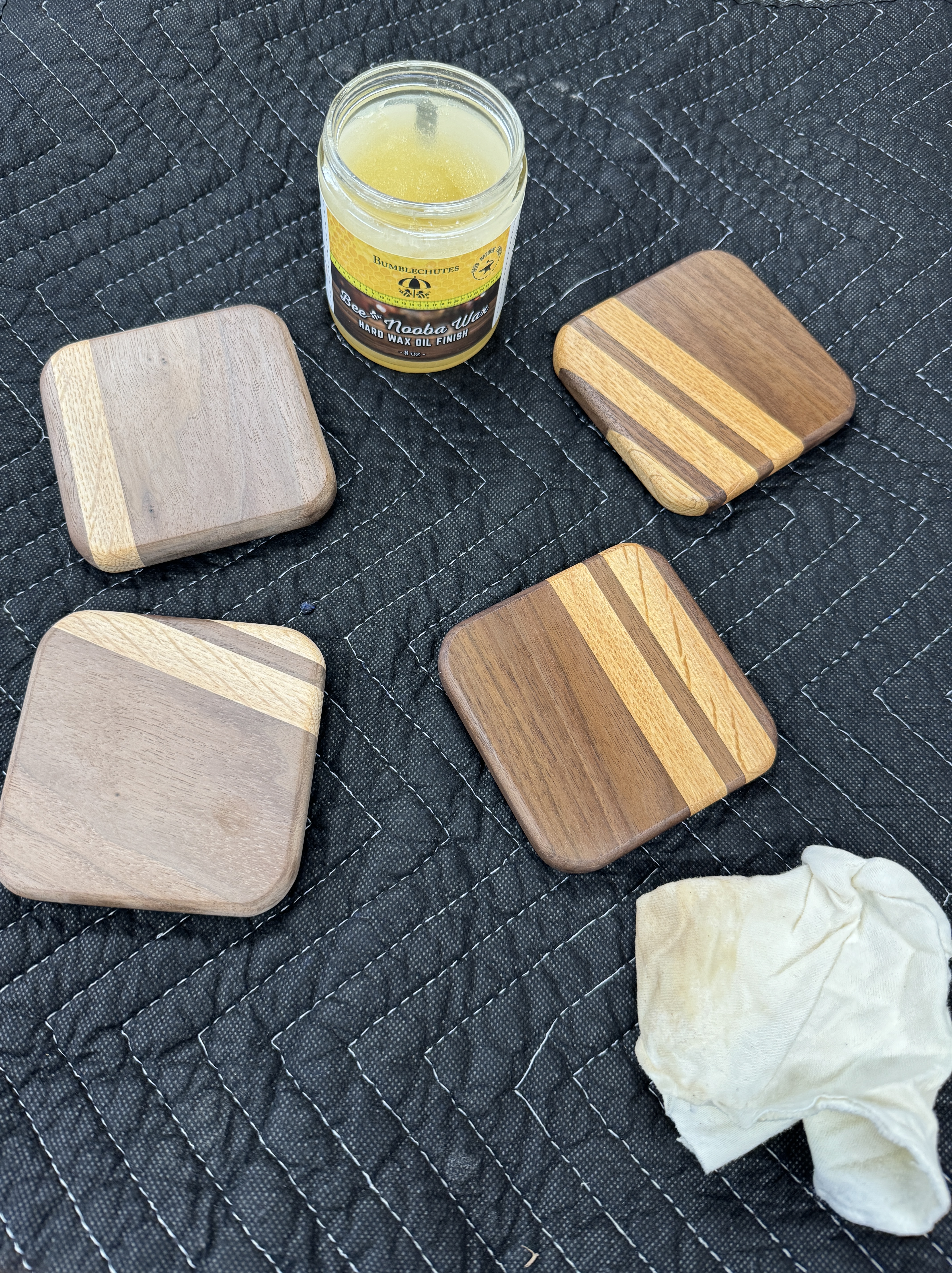
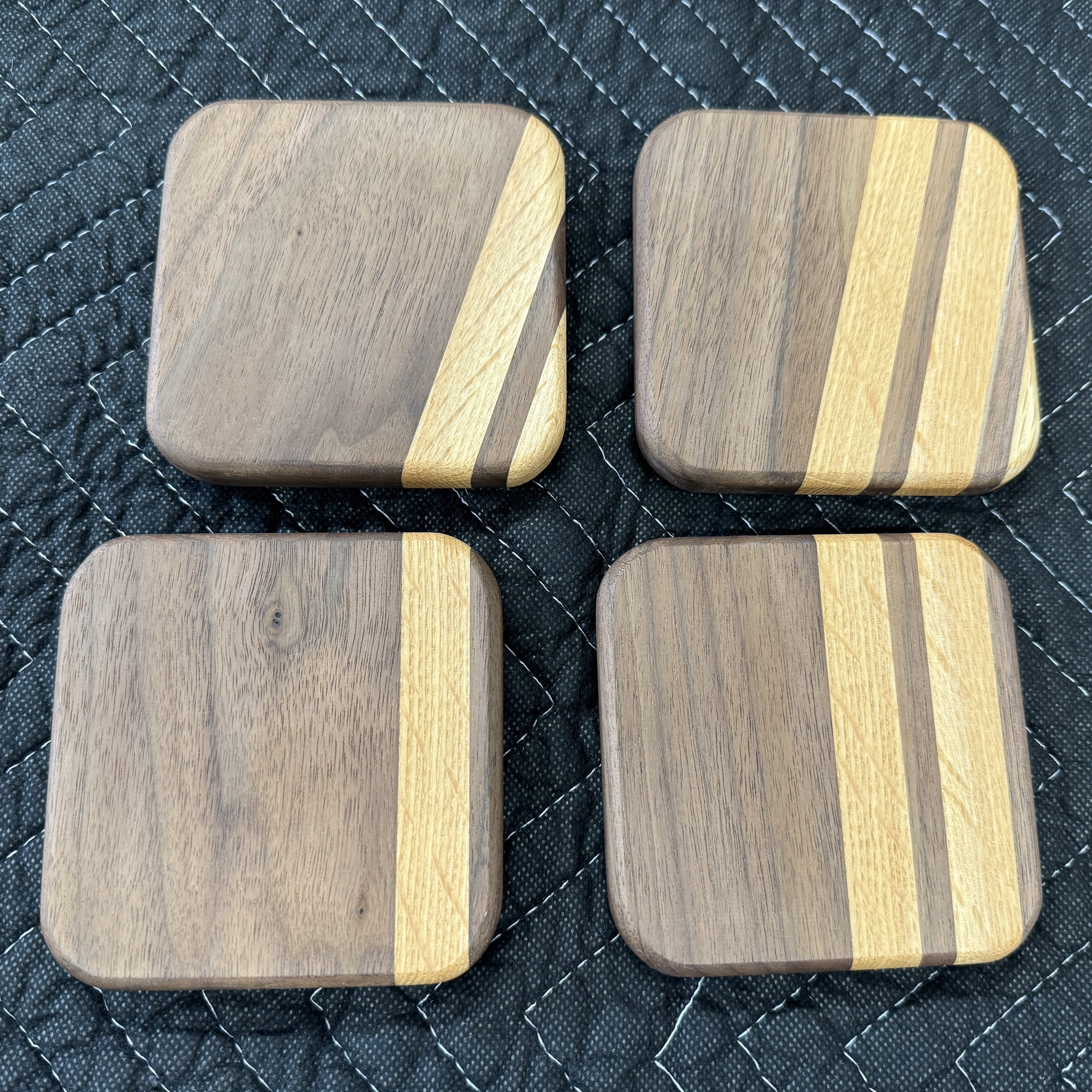
Can you believe I’d never made a set of coasters? Time to fix that.
This was a simple project and a lot of fun to knock out something small. I’ll keep two of the coasters in the office and put the other two in the living room.
Over the years, without success, I’ve tried to stand some while working. Hopefully a motorized adjustable base will encourage me to stand for certain tasks and even if I can do a couple of 20-30 minute sessions each day it’ll be a big help.
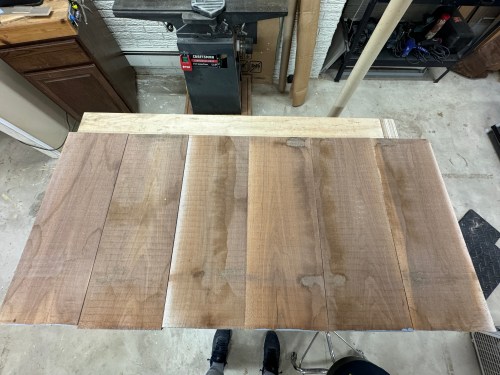
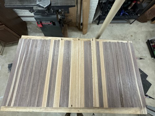
I got to work processing walnut boards and white oak flooring.
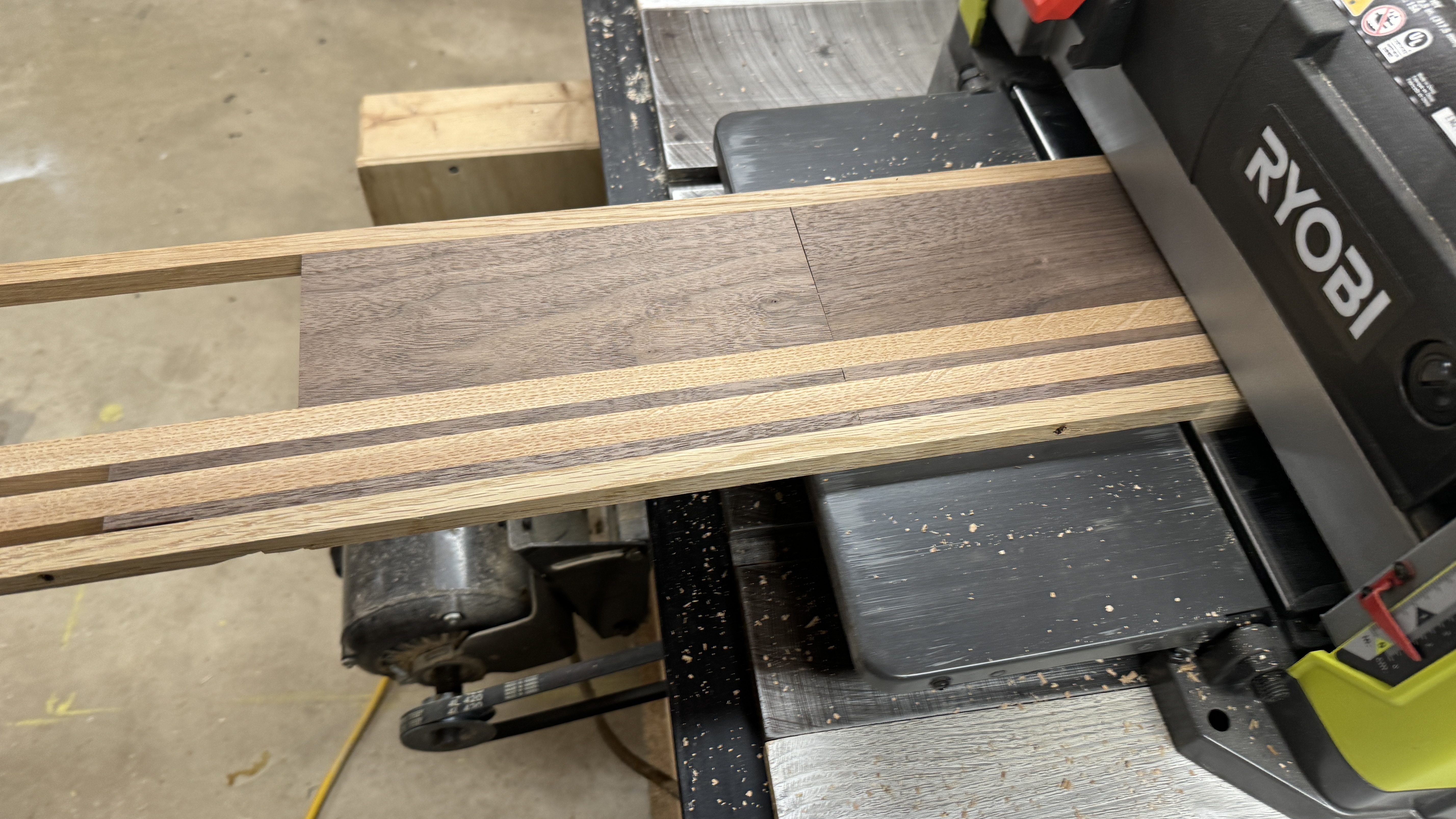
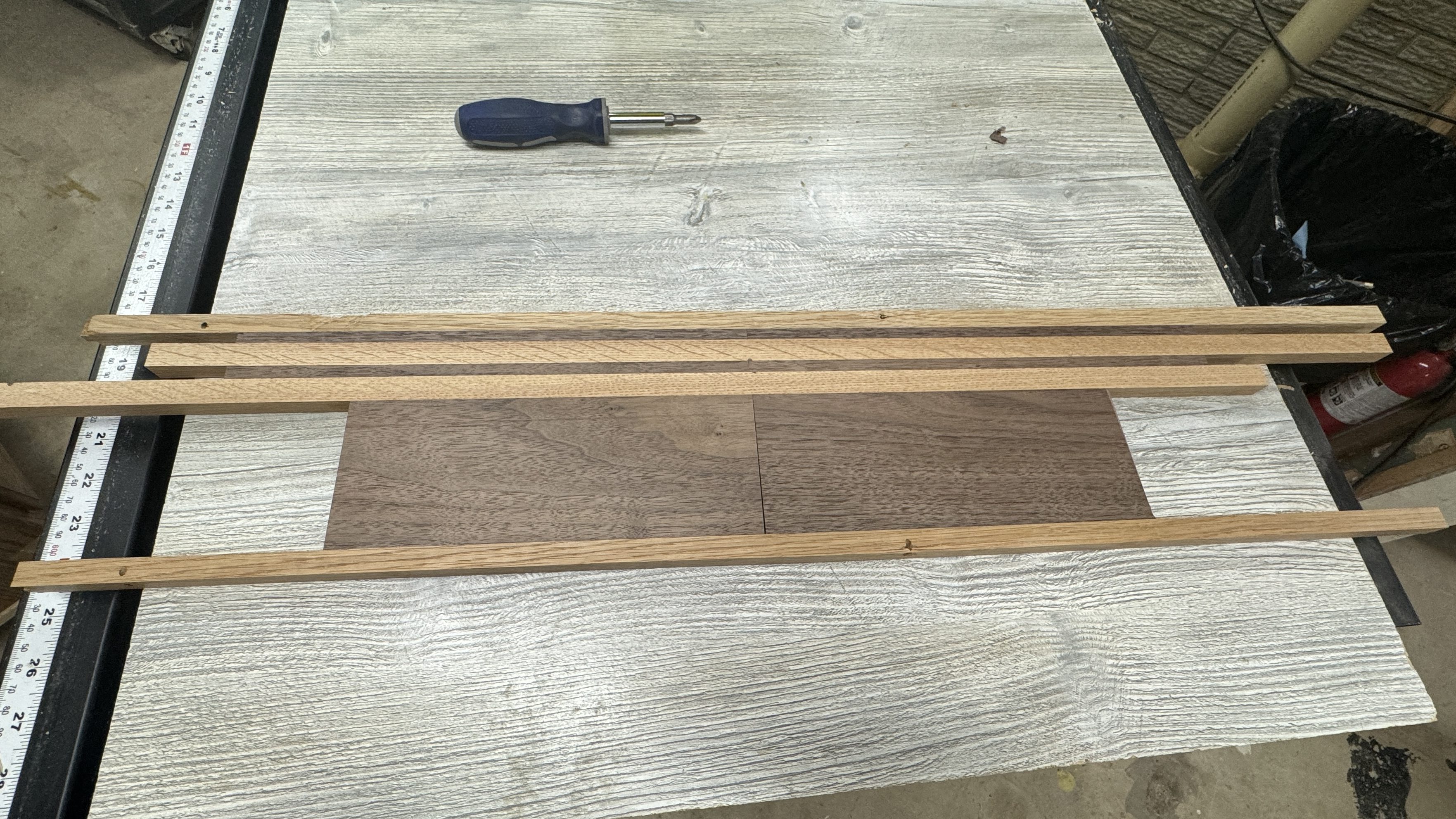
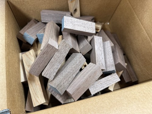
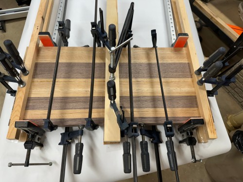
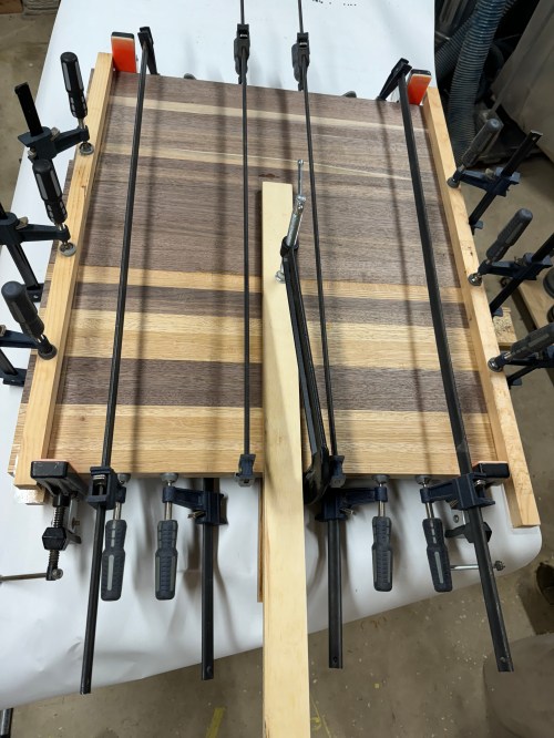
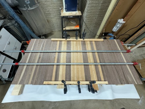
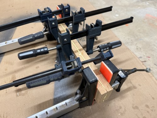
There was a lot of jointing, cross-cutting, ripping, planing, more ripping, and trimming. I’m excited to use that box of off-cuts to make an end grain cutting board or two! I felt like the key to this build was going to be the glue-ups. I started with sections of 9-10 pieces and ended up with eight of those.
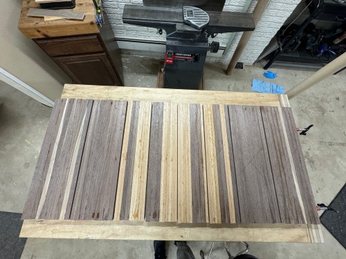
I ran each section through the planer, with the help of some shimming for a couple, to flatten them. I made a temporary sled to square up the sides to the faces.
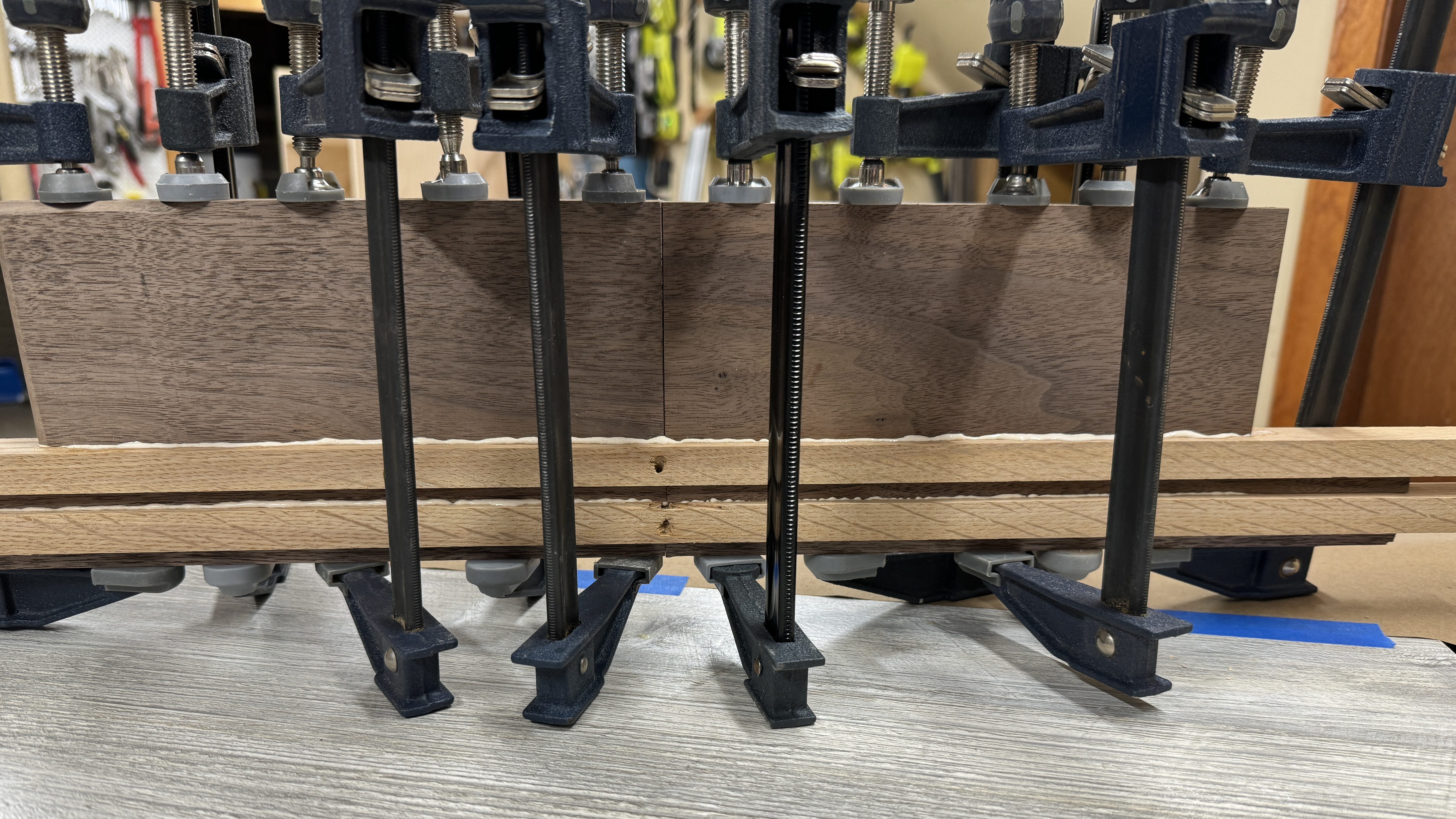
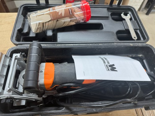
To help assemble the sections, I used a couple of biscuits on each glue joint.
I glued up two sections at a time, which gave me four bigger sections. Then I glued up two of those at a time and one final glue up.
I drilled and put in all of the bolt inserts, which will attach the top to the desk base.
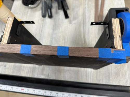
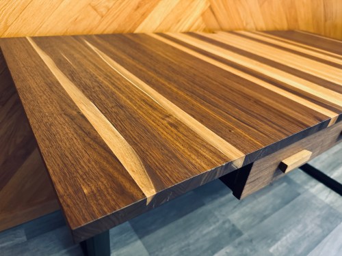
I took three passes with the router to put a big chamfer along the bottom edge.
With a jigsaw, I rough cut out a spot in the back to pass cables through. Then I did some sanding to smooth it out and added a chamfer with the router. Here is it, viewed with the desk bottom facing up.
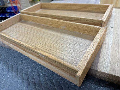
Due to the base’s cross support, there’s was limited depth for drawers, but there was width for them. I took some old kitchen cabinet drawers, chopped them in half, and closed them up with scrap plywood.
Then I worked on what I’m calling the drawer box even though it’s not a box. I also cut top rails from hardboard and oversized drawer faces from walnut. Grabbed strips of walnut for face-framing and glued together pieces of oak to make drawer pulls.
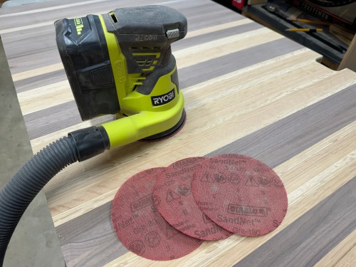
All the sanding! I went through 80, 120, 180, and 220 grits on the top and sides of the desk.
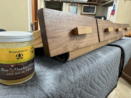
Time to put some finish on, which is always a favorite step to see how it’s really going to look. It was my first time trying out a hard wax oil and I used Bee Nooba Wax from Bumblechutes. It was very easy to apply and I’ll definitely be using it on future projects. I applied one coat to the bottom and three coats to the sides and top.
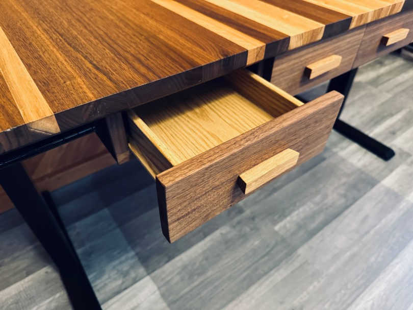
Then it was back to the drawers. I stained the “box” black and ended up having to trim some things to fit better around the rail of the desk base. I sized the drawer faces, made oak handles with 10° angles, assembled everything, and applied finish.
It turned out great! I can’t wait to see it in our new house later this year!
It was a good December for making when I was able to catch up on a lot of electronics kits. I’ve been working on a new desk for my office since November, which I hope to finish soon. Then I’ll be starting to build other things for the new house.
I was given a replacement AC adapter for an Acer laptop, which isn’t compatible with the Dell Optiplex micro PC I wanted to use it with. The output is close enough to work, so I looked for an adapter to convert from the 5.5×1.7mm connector used by the Acer to 4.5x3mm used by the Dell. I couldn’t find an adapter anywhere! I did however find a pigtail adapter on Amazon for about $8 I could wire in. Here’s the original connector and the new cable.
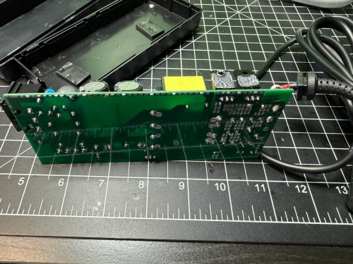
I opened up the power brick.
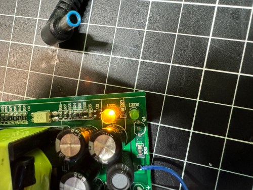
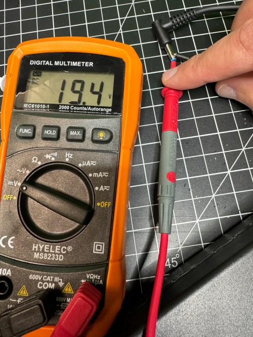
Then I made sure to test the output voltage and the polarity of the wires and connector with a multimeter. I noticed an unused spot for LED1 on the circuit board, so I figured I’d see if connecting a second LED would provide some other status indicator.
All it seemed to do was take over and disable LED2. So I removed it and left the original green LED. I desoldered the original cable, which only had positive and ground wires. The board had a spot with an S, which I assume means “signal,” so when connecting the pigtail, I soldered the blue wire there.
I checked the voltage on the new connector and it was as expected.
I plugged in the Dell and everything seemed to work. I cleaned the old thermal paste off the 3 components that screwed to a big metal heat sink and put on new paste. When I went to close everything I realized the black wire was too short, preventing the cable from reaching the hole in the power brick. I had to solder on a short extension and cover it with shrink tube.
Tucked everything back in the power brick, snapped it together, and it’s good to go.