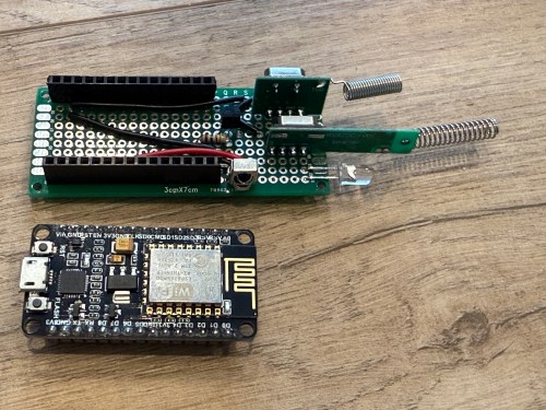
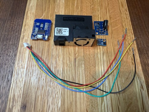
The upgraded IKEA air quality monitors I did work great, but the LED indication isn’t great for a bedroom and the fan noise was annoying in my office. So I wanted to create a couple of my own devices for those locations. I used:
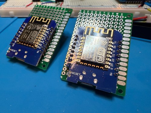
- Wemos D1 Mini (ESP8266) clones
- SEN50 particulate matter sensors
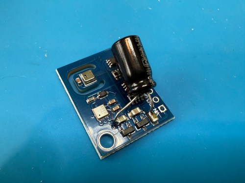
- ENS160 multi-gas sensors
- Si7021 temperature and humidity sensors
- Project boxes
- JST GH 1.25mm connectors and pre-crimped wires
- JST-XH 2.54mm Connector Kit
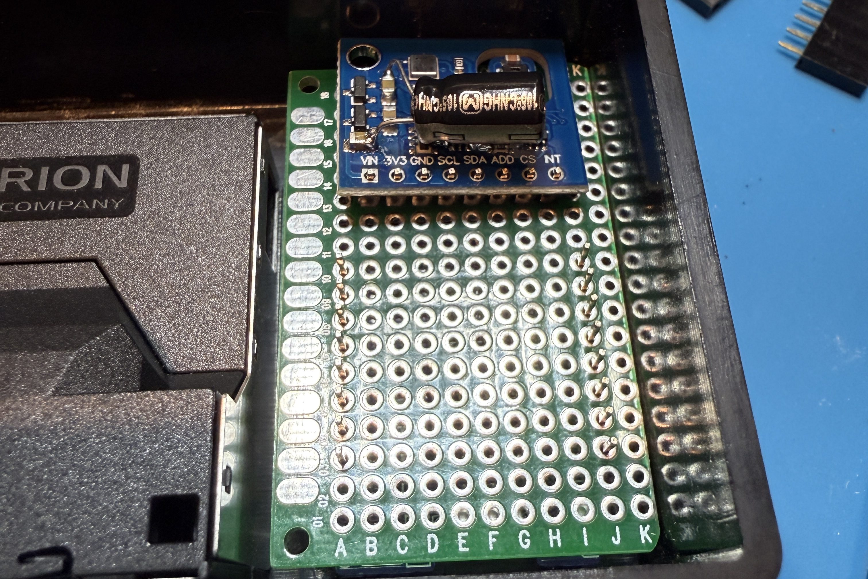
The SEN50 is a big upgrade over the PM sensors used in the IKEA devices and I used the Si7021 in place of the BME280 I had used because I think they’re a bit better. I soldered 47µF electrolytic capacitors from a big kit I’ve had (similar on Amazon) to the ENS150 modules to improve their power.

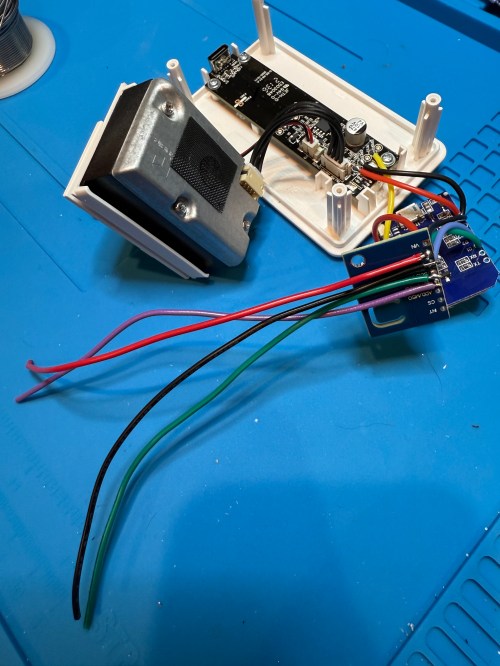
Then I attached 5 of the crimped wires to a 6P JST connector, which is what the SEN50 modules require. I’m note sure why buying the actual cable for these SEN50s are so expensive, but I got the entire JST kit for cheaper than a couple of the special cables.
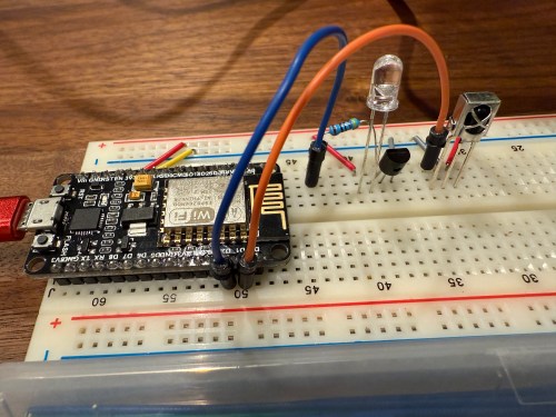
All three sensors communicate with the microcontroller over I²C, so a breadboard test was easy to wire up. The SEN50 does require 5 volts instead of 3.3, so I’m glad I checked.

The ESPHome YAML code is very similar to the code used for the modified IKEA air quality monitors.
substitutions:
  slug: demo
  friendly: Demo

esphome:
  name: ${slug}-wemos-d1
  friendly_name: ${friendly} Wemos D1

esp8266:
  board: d1_mini

logger:
  #level: WARN

api:
  encryption:
    key: 'xxx'

ota:
  - platform: esphome
    password: "xxx"

wifi:
  ssid: !secret wifi_ssid
  password: !secret wifi_password
  manual_ip:
    static_ip: xxx
    gateway: xxx
    subnet: 255.255.255.0

i2c:
  frequency: 50kHz

sensor:
  - platform: sen5x
    pm_1_0:
      name: PM 1µm
      accuracy_decimals: 0
    pm_2_5:
      name: PM 2.5µm
      accuracy_decimals: 0
    pm_4_0:
      name: PM 4µm
      accuracy_decimals: 0
    pm_10_0:
      name: PM 10µm
      accuracy_decimals: 0

  - platform: htu21d
    model: SI7021
    temperature:
      name: Temperature
      id: ${slug}_temp
    humidity:
      name: Humidity
      id: ${slug}_humid

  - platform: aht10
    variant: AHT20
    temperature:
      name: AHT21 Temperature
      id: ${slug}_aht21_temp
    humidity:
      name: AHT21 Humidity
      id: ${slug}_aht21_humid

  - platform: ens160_i2c
    address: 0x53
    eco2:
      name: CO²
    tvoc:
      name: VOC
    aqi:
      id: demo_aqi
      name: AQI
    compensation:
      temperature: ${slug}_aht21_temp
      humidity: ${slug}_aht21_humid

text_sensor:
  - platform: template
    name: AQI Rating
    lambda: |-
      switch ( (int) ( id( ${slug}_aqi ).state ) ) {
        case 1: return {"Excellent"};
        case 2: return {"Good"};
        case 3: return {"Moderate"};
        case 4: return {"Poor"};
        case 5: return {"Unhealthy"};
        default: return {"N/A"};
      }
These resources helped out:
- D1 Mini Pinout Reference
- ESPHome: I²C Bus
- ESPHome: Sen5x Series Environmental sensor
- ESPHome: ENS160 Sensor
- ESPHome: AHT10 Sensor
- Home Assistant Forums: ENS160 Stability issues
- ESPHome: HTU21D | Si7021 | SHT21 Temperature & Humidity Sensor
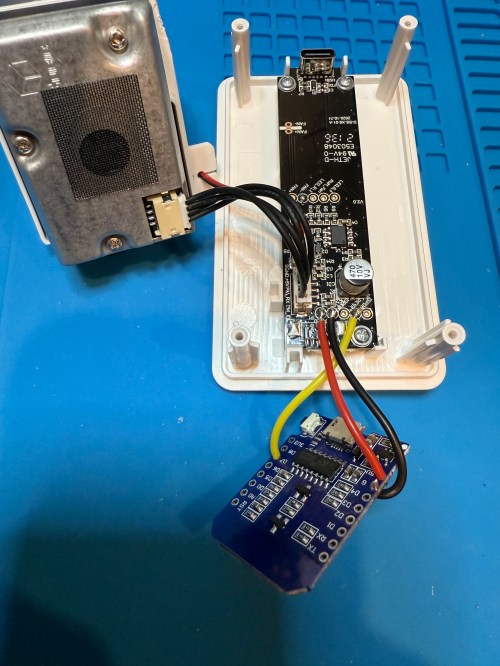
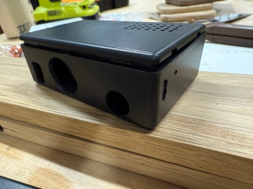
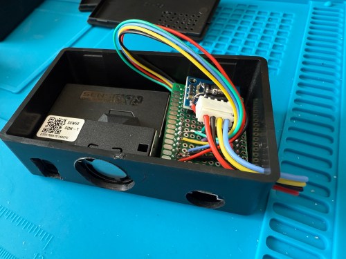
The project boxes had some standoffs on the bottom, which I snipped off and then sanded with a rotary tool. I pulled out my box of proto boards and found a size almost exactly double what I needed, so I cut out a sliver and ended up with a piece for each box. I also cut vent holes for the SEN50 sensors.
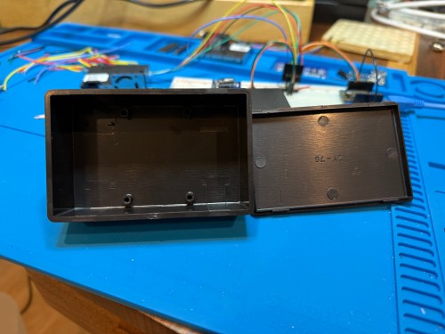


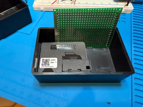


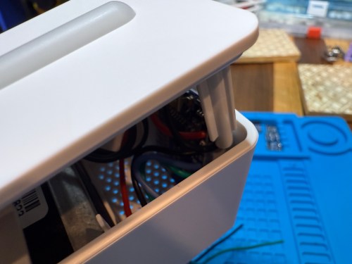
In order to get everything to fit I decided to put the microcontroller on the bottom of the board. After mocking things up I did all of the soldering. I was hoping to be able to mount everything with connectors so it could easily be taken apart, but there wasn’t enough room and I didn’t want bigger boxes.


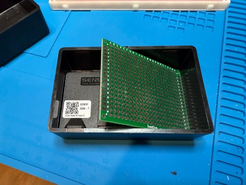
I did some continuity testing along the way and everything worked when I connected power. With the boards ready I cut more access and ventilation holes in the boxes.


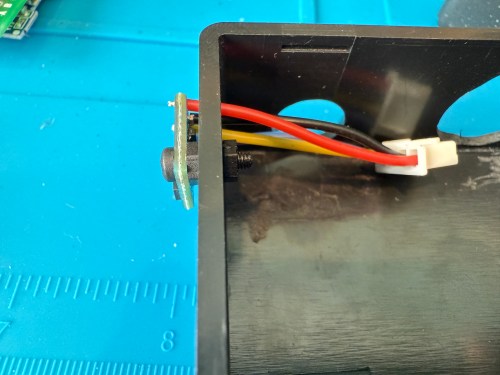
I soldered the Si7021 on to its wires outside of the enclosure so it wouldn’t be exposed to unnecessary heat and used hot gun to secure everything.


I’m really happy with how these turned out. Here’s a view of the office data on my Home Assistant dashboard.

This was definitely a project where I wished I had a 3D printer to design custom boxes. Some day, when I’m caught up on my project list and can give it proper attention. I know if I get one now I’ll spend a ton of time with it and neglect other projects in my pipeline.