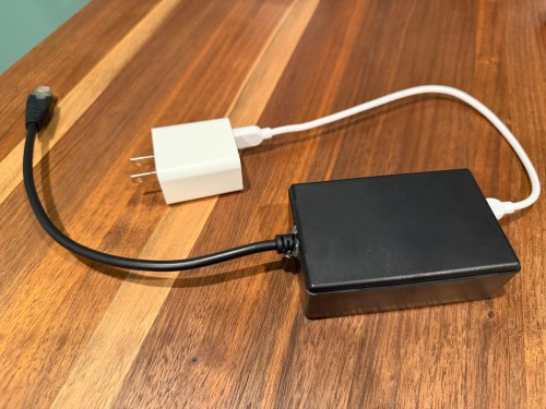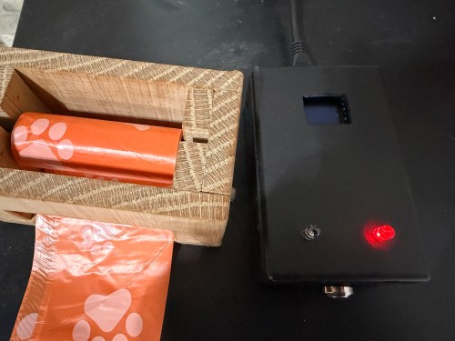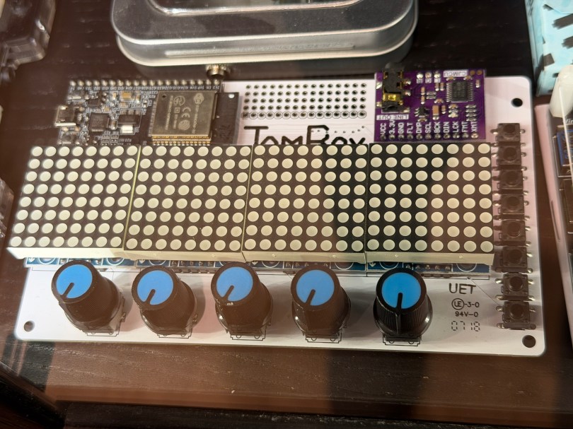
Not long ago the old JamBox sitting in one of my office display case’s caught my eye.

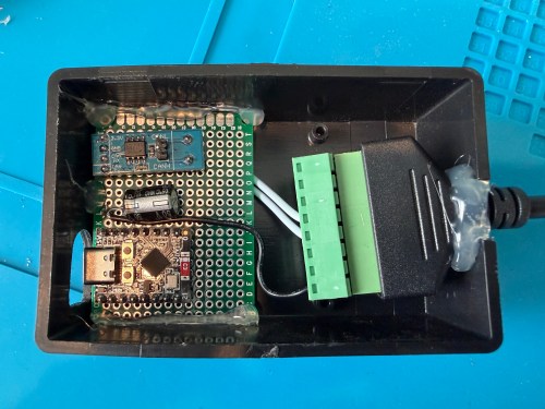
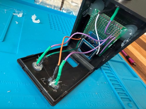
After picking it up I noticed it used an ESP32 development board, so I had to flash it for ESPHome. I downloaded the PixelOperator8 font and uploaded it to my esphome/fonts folder in Home Assistant. Then I figured out the following YAML to get the buttons, potentiometers (knobs), and LED Matrix working.
# Include your standard api, ota, and wifi sections

esphome:
  name: jambox
  friendly_name: JamBox

esp32:
  board: esp32dev
  framework:
    type: esp-idf

bluetooth_proxy:
  active: true

spi:
  clk_pin: GPIO14
  mosi_pin: GPIO12

font:
  - file: "fonts/PixelOperator8.ttf"
    id: pixel_font
    size: 8

display:
  - platform: max7219digit
    id: jambox_display
    cs_pin: GPIO15
    num_chips: 4
    intensity: 1
    rotate_chip: 90
    lambda: |-
      it.print(0, 0, id(pixel_font), "JamBox  ");

binary_sensor:
  - platform: gpio
    name: "Button 1"
    pin:
      number: GPIO4
      mode: INPUT_PULLDOWN
  - platform: gpio
    name: "Button 2"
    pin:
      number: GPIO5
      mode: INPUT_PULLDOWN
  - platform: gpio
    name: "Button 3"
    pin:
      number: GPIO16
      mode: INPUT_PULLDOWN
  - platform: gpio
    name: "Button 4"
    pin:
      number: GPIO17
      mode: INPUT_PULLDOWN
  - platform: gpio
    name: "Button 5"
    pin:
      number: GPIO18
      mode: INPUT_PULLDOWN
  - platform: gpio
    name: "Button 6"
    pin:
      number: GPIO19
      mode: INPUT_PULLDOWN
  - platform: gpio
    name: "Button 7"
    pin:
      number: GPIO21
      mode: INPUT_PULLDOWN
  - platform: gpio
    name: "Button 8"
    pin:
      number: GPIO23
      mode: INPUT_PULLDOWN

sensor:
  - platform: adc
    name: "Knob 1"
    pin: GPIO32
    update_interval: 100ms
    attenuation: auto
    unit_of_measurement: "%"
    accuracy_decimals: 0
    filters: &knob_filters
      - calibrate_linear:
          - 0.15 -> 0.0
          - 3.13 -> 100.0
      - clamp:
          min_value: 0.0
          max_value: 100.0
      - round: 0
      - delta: 1.0
  - platform: adc
    name: "Knob 2"
    pin: GPIO33
    update_interval: 100ms
    attenuation: auto
    unit_of_measurement: "%"
    accuracy_decimals: 0
    filters: *knob_filters
  - platform: adc
    name: "Knob 3"
    pin: GPIO34
    update_interval: 100ms
    attenuation: auto
    unit_of_measurement: "%"
    accuracy_decimals: 0
    filters: *knob_filters
  - platform: adc
    name: "Knob 4"
    pin: GPIO35
    update_interval: 100ms
    attenuation: auto
    unit_of_measurement: "%"
    accuracy_decimals: 0
    filters: *knob_filters
  - platform: adc
    name: "Knob 5"
    pin: GPIO36
    update_interval: 100ms
    attenuation: auto
    unit_of_measurement: "%"
    accuracy_decimals: 0
    filters: *knob_filters
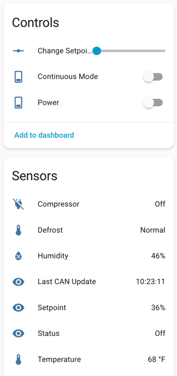
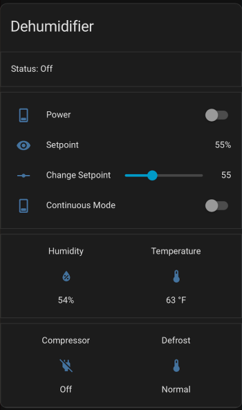
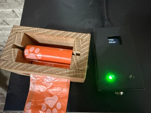
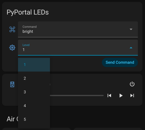
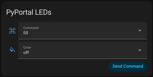
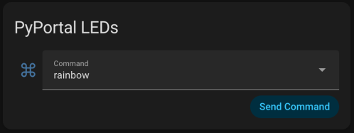
After installing the YAML and installing the device to Home Assistant, here are the sensors in the device UI.
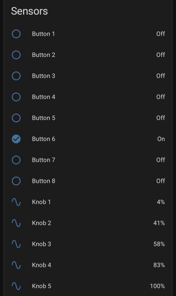
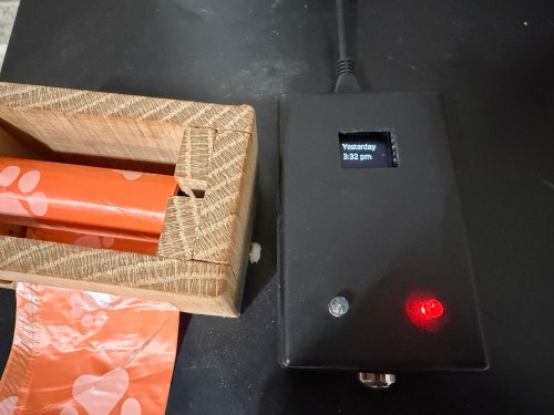
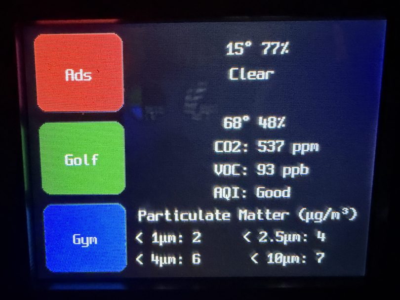
The device has a ton of inputs with the eight buttons and five knobs and the 8×32 LED Matrix can display text or maybe a simple graph. I haven’t thought of a good use for it though. Do you have any ideas?