Several years ago I bought this sign from T.J.Maxx.
When I plugged it in, I was disappointed. By default it was off with a button on the side to toggle between bright, dim, and off.
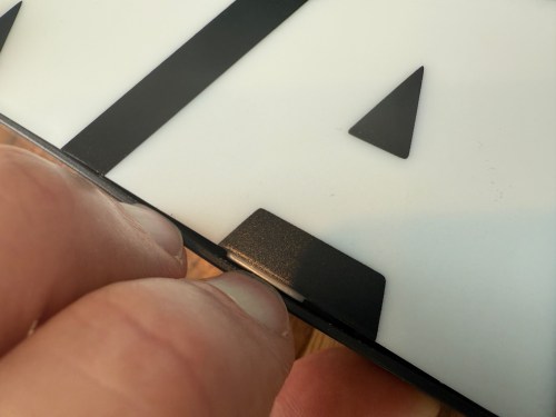
I put the sign in a display cabinet with all of the LEGO and I had wanted it to automatically turn on with the rest of the LEDs in the cabinet. I never got to it, so it sat on the shelf for years. Fast forward to setting up home automations at the new house and it was time to fix the problem. The only screw on the back was for opening a battery compartment, so I figured the front had to be snapped in. With a little careful persuasion I gained entry.
I figured the electronics were pretty basic and I was right. The quick fix was to connect the sides of the button/switch.
That worked, but I noticed how flimsy all the wiring was. I replaced the wires going from the USB connector to the board, which had been causing some flickering when bumped.
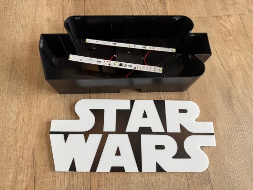
I was sad at the lack of LEDs though. I could do better, with minimal effort. I took out the circuit boards and found an old five volt LED strip.
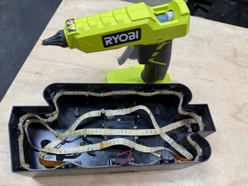
With the help of some double-sided tape, I wrapped the strip throughout the case and then also used hot glue.
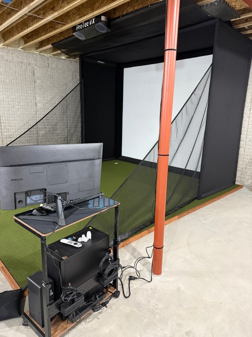
In order to automate the processes of getting the golf sim ready to play and shutting it all down when finished I needed to create a remote control device. I’m using Home Assistant (HA) to run my home smart system (more posts to come), but two things involved with the golf sim aren’t connected to the network:
The projector has an infrared (IR) remote and the light has a radio frequency (RF) remote. I’ve done somethings with IR and still had a stash of IR LEDs (for transmitting) and receivers. I’ve never attempted any RF stuff, so I ordered a 5 pack of 433mhz wireless RF transmitter and receiver pairs.
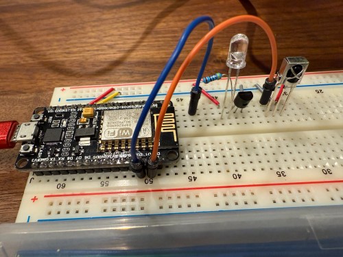
Since I’m using HA, I let ESPHome handle all of the main programming. All I had to do was wire everything properly and get the configuration correct. I made use of an old ESP8266 NodeMCU microcontroller and worked on the IR aspect of the project first.
When I took the picture I was using a 470Ω resistor, which I eventually switched to 100Ω, to increase the strength of the IR signal. The transistor is a PN2222A. Here’s the ESPHome configuration:
I used the receiver to intercept the codes sent by the projector’s actual remote when pressing the Power, Input, and OK buttons. Then I created some buttons.
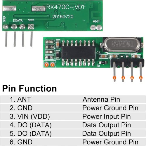
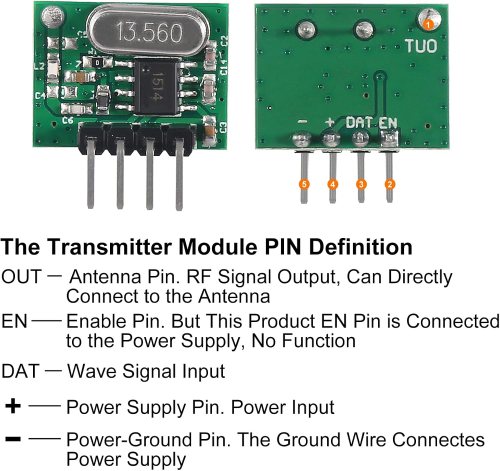
It all went very smooth. Next I connected the circuits for the RF components, which was straightforward. Here are the pinouts from the Amazon product page.
I soldered on the antennas (smaller one to the transmitter) and connected everything on the breadboard.
By using examples from the documentation I was able to intercept RF codes.
When I tried to recreate those codes through the transmitter the results weren’t matching up and the spotlight wasn’t responding. It took some trial and error to configure the various parameters of the receiver. Here’s the end result, with the combined configuration for IR and RF.
After using the remote_receiver instances to get the button press codes I needed, I commented out that section of the code. If I ever need to add more functionality to my remote, I can enable the receivers at that point. Here are the button codes for the spotlight.
Then I was able to use both sets of buttons in scripts, which can feed to Alexa for voice commands.
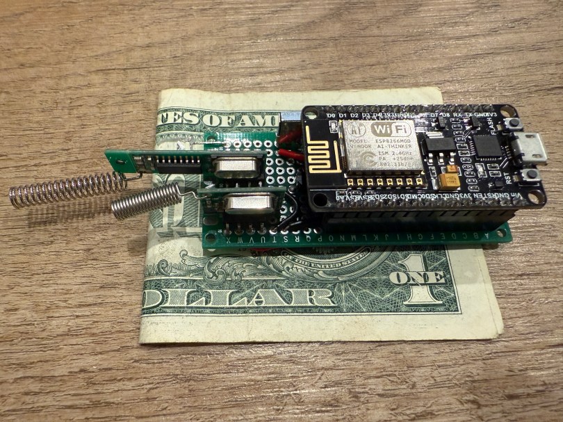
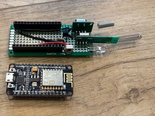
Once everything was tested I wired and soldered a more permanent circuitboard. I included a folded dollar bill for scale.
I was planning to mount it in the ceiling, but the IR was having trouble, because the projector’s receiver faces the ground. Mounting it to the side of the PC cart worked great.
This was a lot of fun!
Update: Less than a week later I’ve already modified it, by adding a DHT22, which reports temperature and humidity. Might as well use that empty D7 pin on the microcontroller.
A big part of the planning for our house included Ethernet wiring because I want to hardwire every device I can, saving the Wi-Fi for devices that require it. It’s much easier and cheaper to get everything wired during the build, instead of adding later. I went through several iterations of the plan and in the end I had the electricians do 42 runs of Cat6:
4 jacks in the office
2 jacks in the office closet
2 jacks in the pocket office
2 jacks in the guest bedroom
4 jacks behind the TV
2 jacks in the living room
2 jacks in the dining room
2 jacks in the pantry
2 jacks in the laundry room
4 jacks in the walk in closet
6 jacks in the master bedroom
10 wires to 5 exterior camera locations (1 extra at each location)
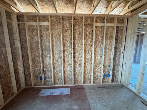
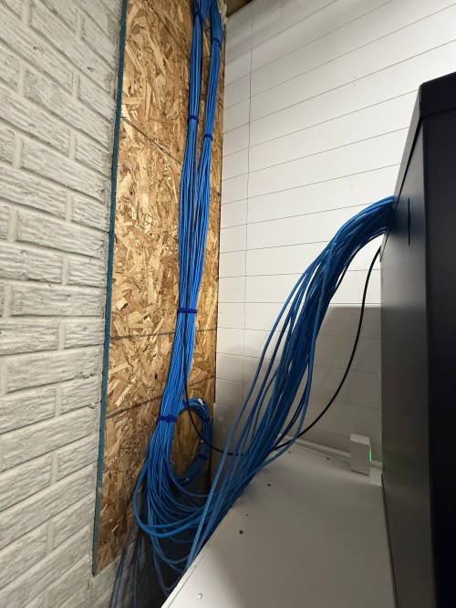
They run it all up through the ceiling. I’m guessing that is to keep it away from most of the electrical. Here’s the master bedroom nightstand wiring as an example.
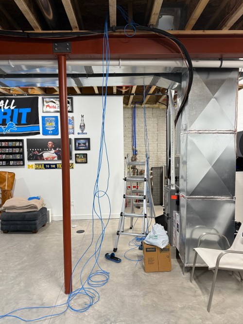
Then all of the cables comes over and down a wall between the laundry room and garage.
Ending at a single location in the basement.
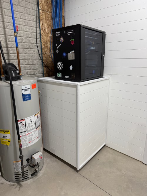
We built a wall (part 1 & 2) and since we moved in back in August I’d had the cable modem and old eero router sitting on top of the network rack filled with new equipment.
Throughout the house, I put port covers on the unused jacks. Here’s how a wall plate looks with one port open and one covered. The covers will help protect the internals and keep dust out.
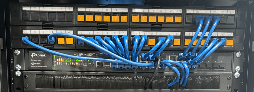
What did I buy for my network? A LOT! Here’s all of the stuff for the rack, cables, and tools.
When it came to the actual networking equipment I took a good look at the stuff from Ubiquiti/UniFi. It’s top of the line, which is reflected by the price tag. I decided to go with TP-Link instead, saving a lot of money.
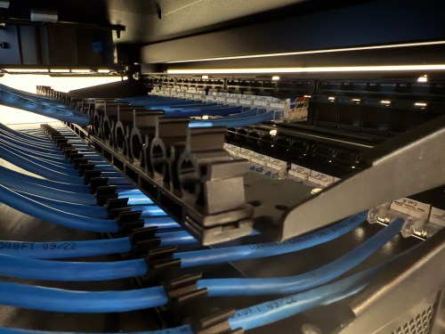
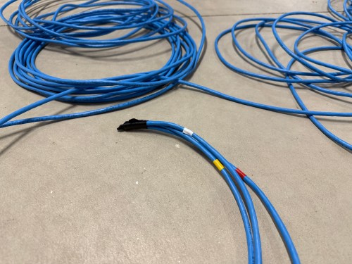
Before I started wiring everything through the rack, I cleaned up the cables.
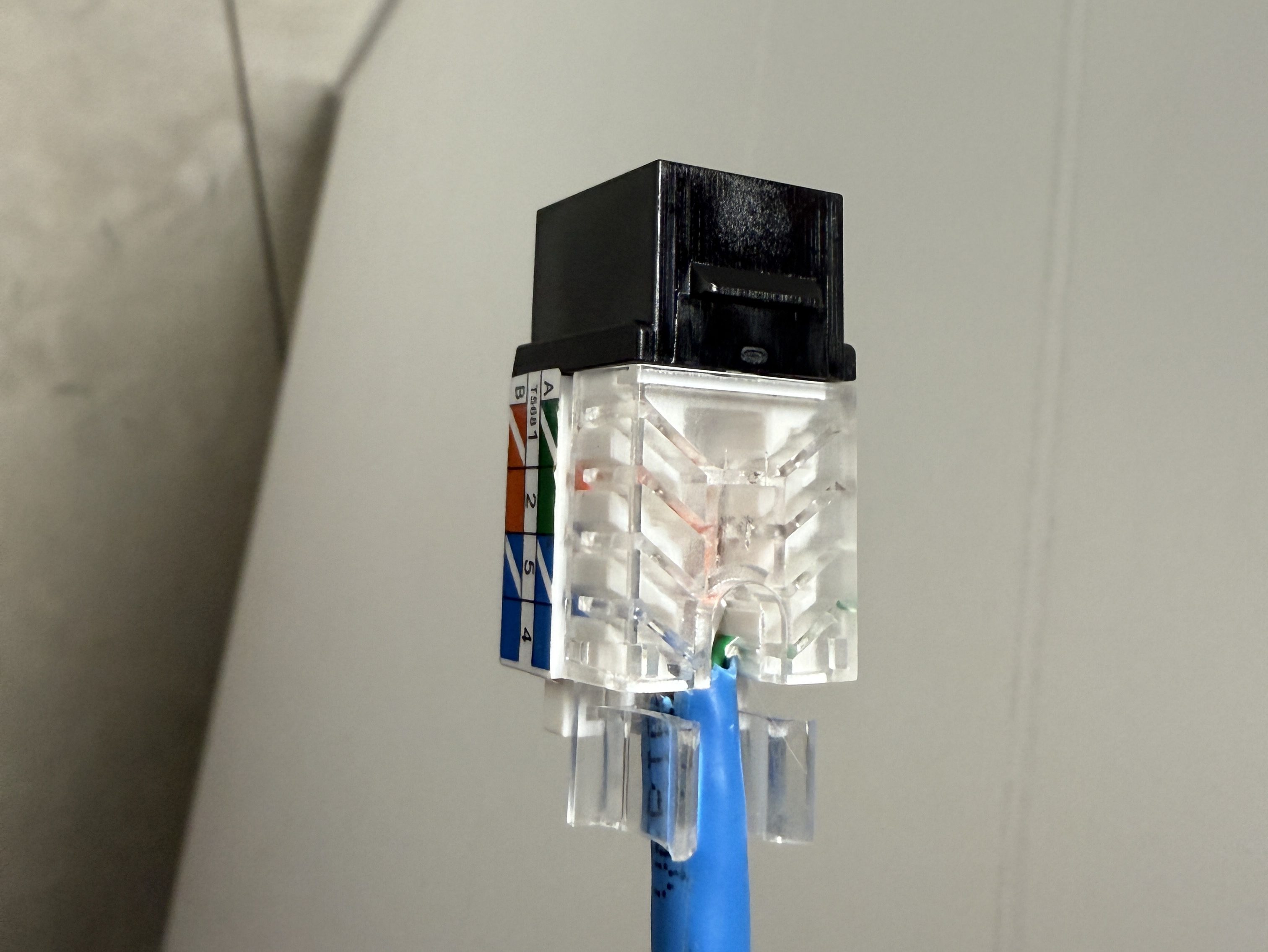
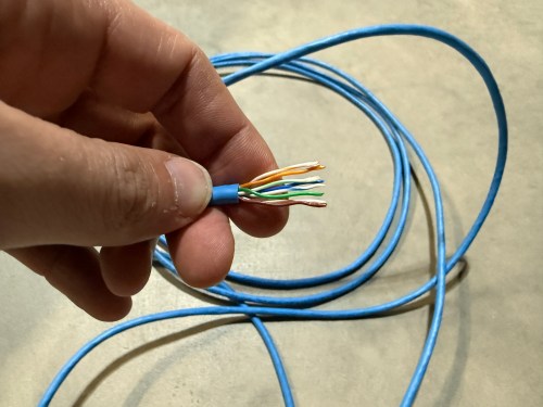
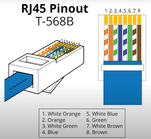
The electricians had done all of the wall jacks throughout the house with the newer T-568B wiring standard, so I followed suit. I learned how to wire the keystone jacks and insert them in to the patch panels.
I’d never done anything like this and it was so much fun. By the end, I was pretty quick with each keystone jack. I highly recommend the Everest 45° ones and the tool for it. The basement needed some Ethernet ports for the golf sim, so I ran four new cables from the rack. I installed a couple of electrical boxes in the ceiling and wired jacks there.
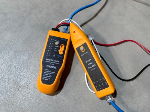
I also needed a custom length Ethernet cable to run from the ceiling jack down to the gaming PC. I’d tried putting RJ45 jacks on the end of an Ethernet cable or two a long time ago and remember it being almost impossible. After watching a quick YouTube video (even though I don’t have pass through connectors), I was able to put both ends on my new cable without a problem and it passed the test.
Then I was able to use patch cables to connect ports on the patch panel to the switch as well as hook up the cable modem, Pi-hole Raspberry Pi, and TP-Link equipment. There’s also a Dell Micro in there, which I’ll cover in a later post about smart home.
When I tried to access the Omada controller I couldn’t bring up the web interface with Chrome on my Mac. After trying a bunch of stuff I checked from my iPhone and it worked. I tried Safari on my Mac which also worked. It turned out I had always prevented Chrome from accessing my local network. I flipped the switch in System Settings and the interface loaded.
At another point I accidentally disabled all of the ports on the switch. The UI splits the switch ports across three pages, and on page two I had clicked the button to select all, unselected a port, and disabled the nine other ports. I quickly realized it disabled 27 of the 28 ports. I was so pissed! Every other UI I’ve ever used will only select the items in view when you click the Select All button, but not the Omada Controller software. In order to get back in I had to access the switch via the USB console, reset the switch to factory settings, and start over.
I’m running four VLANs, named Default, Guest, IoT, and nIoT. IoT is for my Internet of Things (smart home) devices that need to access the Internet and the “n” in nIoT stands for “not” since I don’t want them to access the Internet. The Default and IoT networks are set to get their DNS from my Pi-hole server, which blocks ads and other malicious domains.
Each VLAN has a matching wireless network. The Guest Wi-Fi is set as a guest network, which automatically prevents any device from accessing another. The wireless networks for IoT and nIoT are only set to use the 2.4 GHz band since most of the devices will not work on 5 GHz.
I added mDNS rules for Printers and AirPlay devices from the IoT network to the Default network.
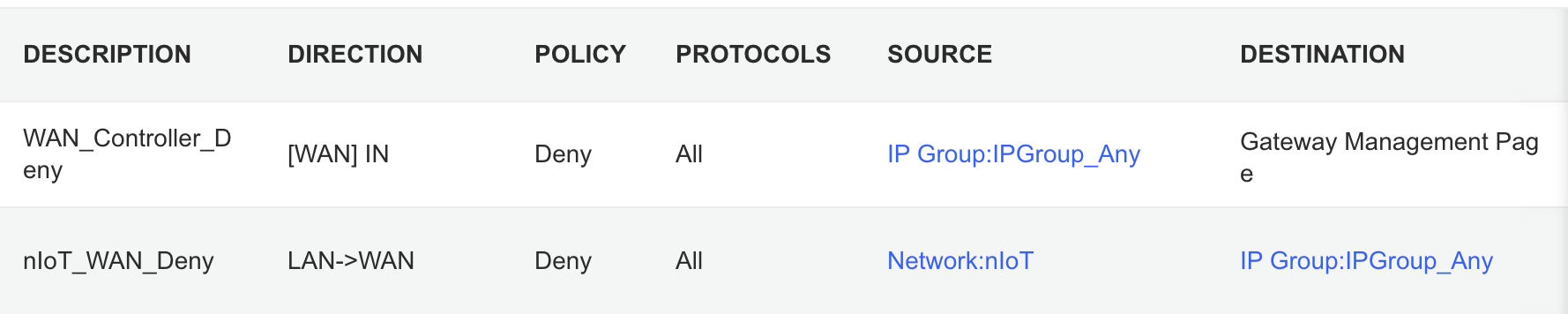
It took me awhile to figure out the ACL rules. I have two for the Gateway. The first prevents any outside IP from accessing my network management page and the second prevents the nIoT network from accessing the Internet.
I ended up with six rules for the switch, since the default behavior of the Omada stuff is to permit everything. With my Pi-hole server on the IoT network I had to allow it’s IP to access anything on the Default network (this should probably be limited to specific ports). I had to allow some ports from the camera IPs to access the Default network and I had to allow some ports from my Home Assistant server to access the Default network. I may find out I need to adjust those ACLs, but more on those smart home aspects in a future post. Then the IoT and nIoT networks are denied from accessing Default and a bi-directional rule prevents the Guest network from accessing any other network.
Seems to be running pretty well. I have some smart home stuff on the network, but haven’t connected any of the light switches yet and have a lot of Home Assistant configuration to do. Originally I didn’t have an access point in the basement, but after a few days realized it was necessary and added one. Here’s a view of the network topology, automatically generated by the Omada controller.
If you upload a floor plan and place walls, the software can even run a wireless coverage simulation. The house has great signal and the yard should get good connections as well.
Power over Ethernet is pretty sweet. It’s so nice not needing power cables for the 10 devices with PoE support.
Time to finish setting up my server and smart home devices. Watch for an upcoming post with all of the details.
There were two large projects in the new house with the wall for the gym/shop and then the golf sim. Working in the new shop is a joy and will get even better after I build a big assembly/outfeed table.
I’m looking forward to continuing the momentum of November and December in to 2025 and hope to tackle smaller projects through the entire year.
This is the third post in this series about putting a golf simulator in our basement. Part one covered the PC build and part two was all about theenvironment. This one will cover all of the other electronics and some things that didn’t fit in the first two posts.
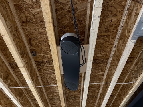
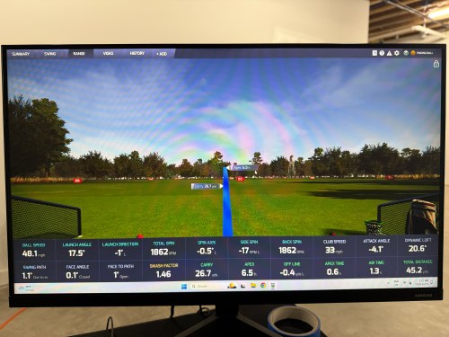
The launch monitor is the piece of equipment that “watches” you hit the golf ball and determines the spin, speed, direction, and angles. I guess you might call it the brains of the operation.
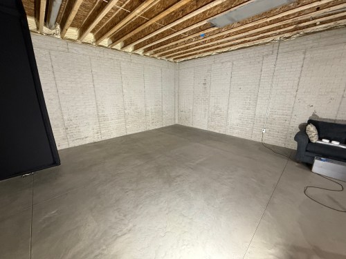
Before installing the unit, I had to do some electrical work in the basement. I removed a couple of lights in the area, rewired some lighting circuits, and added three outlets in the ceiling.
In order to mount the launch monitor to the ceiling I cut a piece of 3/4″ plywood that could fit in between the joists, resting on the bottom of the I-beams. Then I was able to attach the mounting plates directly to the plywood while I was on the ground. I even locked the launch monitor in to the mounting plate and then lifted the entire assembly up to the ceiling. I felt like it was so much easier than trying to align things while working above my head. This also gave me the flexibility to slide it sideways to dial in the placement. I eventually screwed the plywood to the joists.
At this point I didn’t have the turf and the side netting wasn’t installed. I couldn’t resist and had to hit a few shots. Here’s the very first hit, which was a little chip with an 8 iron.
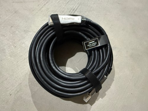
Due to the distance from the PC to the projector being more than 10 feet, a normal cable wouldn’t work. I snagged a fiber optic HMDI cable from Target. I didn’t need 50 feet, but I had a gift card to use there. It took me a bit to realize this type of cable isn’t bidirectional.
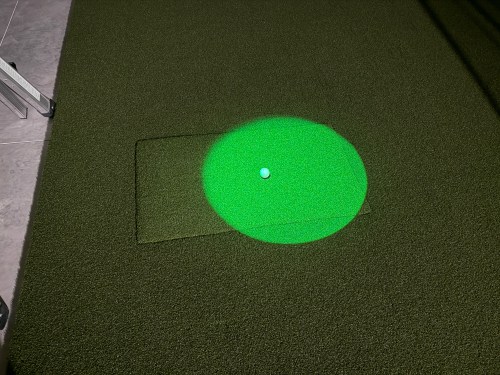
Since most of the basement lights need to be off when using the simulator for a crisper image, I picked up a spotlight to point at the hitting area (the green is quite nice) and a track light (bulbs).
The launch monitor comes with ProTee Labs, which shows ball and club data and allows you to hit on a range. In order to play golf and have other practice options, I got the yearly subscription to GSPro, which is exceptional!
Not necessary for the golf sim, but I bought another Apple TV 4K and a mount. It’s connected to the projector so we can watch movies, football, or anything else. I need to figure out a sound system.
There were several other small purchases, such as an extension cord to run power to the PC, velcro tape to tidy up the wires running down the post, and parts to do the electrical work.
Here’s a video of the golf simulator in action.
I’m excited to see where this can take my golf game. I’ve already started The Strike Plan (from The Practice Manual‘s author) to improve my ball striking and I’m hoping to spend time daily working on my game or having fun with it.
The normal price of the ProTee VX is $6,500 before tax, but I got a bit of a holiday discount. The total cost for everything in this post was a whopping $9,049, bringing the grand total to $14,699. I feel like that’s middle of the road for a home golf sim because you can get really cheap or you can spend more on just a launch monitor! If you have any questions about anything, leave a comment and I’ll be happy to share more.
After I’ve spent more time using the simulator I’ll post some thoughts. There will also be some upcoming side projects.
A couple of weeks ago I wrote the first post in this series about putting a golf sim in our basement, which focused on the PC. This post will focus on the environment.
When we built our home, we did 10 foot basement walls, knowing we’d be putting in a golf sim. This gave us about 9’8″ from the concrete floor up to the joists, which is plenty of room for me to swing every club in my bag.
Back in April, during a Masters sale, I ordered the SIG12 Golf Simulator Enclosure and Side Barrier Netting from The Indoor Golf Shop. By following their setup video, it was very easy to put together. Later in the process, I used a hairdryer to smooth out the wrinkles and fold lines, though I’m not sure it helped much.
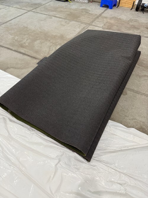
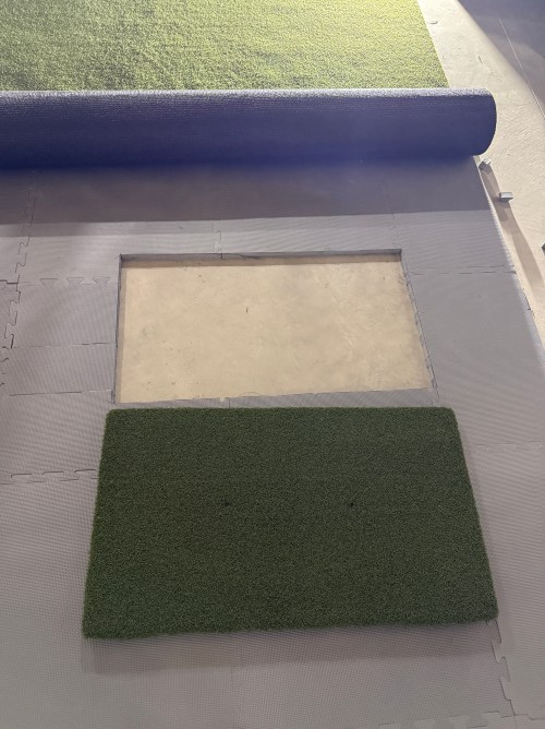
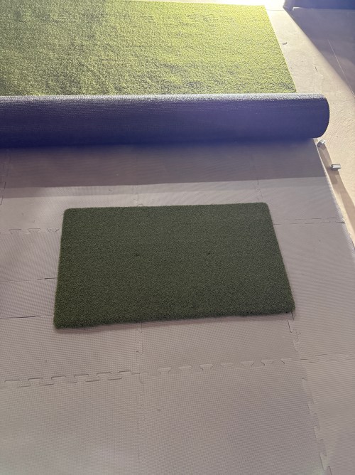
The next thing I got was the hitting strip, which is one of the most important aspects of a sim because you want it to hold up for a long time, while protecting your wrists. I bought The Original Country Club Elite based on the price and reviews. The strip is 20×36″ and just under 1-3/4″ thick.
After knowing the thickness of the hitting mat, I could focus on the mats and turf to surround it. I did a lot of online searching and didn’t find many recommendations, which was surprising. A Reddit thread pointed me to the ProGrass ProPutt at Lowe’s and they ship a 8×8″ sample only $1!
It felt nice and from what I’d read, a face weight of 50 oz was good for this type of use. I took the sample over to Menards and compared it to their 44 oz.
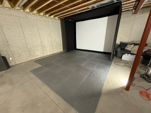
The choice was clear, so I made an order at Lowe’s for a 13×15′ piece. To create the base and a cushion under the turf I ordered 1″ thick puzzle mats from Amazon.
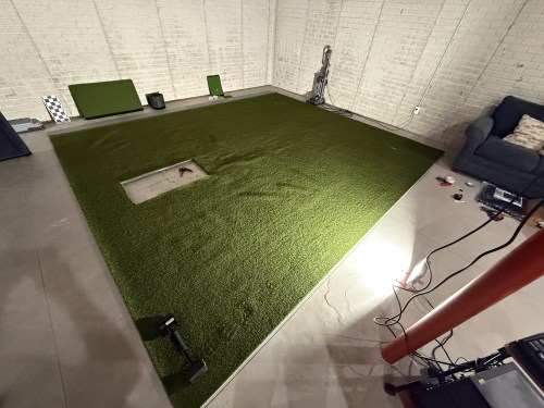
Quickly after we put together the enclosure and got a feel for the space, we decided to rotate to the adjoining wall.
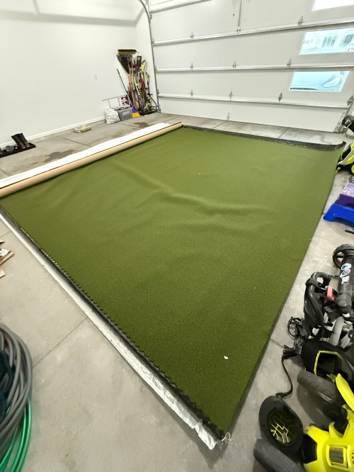
The turf finally arrived and I trimmed off the factory edges and cut the width to 13 feet. After hauling it to the basement I cut out the locations for the hitting strip and a couple of 1.5″ shallow putting cups. The cups were actually too tall, so I shortened them to 1-1/8″ on the table saw. Cutting the holes in the turf was nerve-wracking. Too tight and the turf bubbles around the thing you’re inserting. Cut too much of the turf, making it too loose, and you can’t go back. I bought a carpet knee kicker for stretching out the turf to remove the wrinkles and bubbles.
Brandi was a big help with the turf. I’ve never done any carpet work, so I’m amazed at the level of flatness we achieved. I’m pretty sure neither of us has a future career as a carpet installer though. I had some good carpet tape for the edges, that we ran out and the light duty stuff I picked up from Menards was useless, so I ended up buying more of the good carpet tape from Amazon.
I filled the sandbags and installed the side netting.
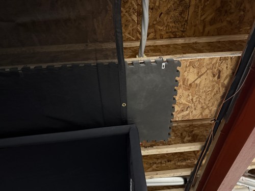
To help protect the ceiling from sky balls and prevent anything from going through the heating ducts, I screwed OSB over the duct and 2 layers of old puzzle mats. I also bought a 10×12′ mesh tarp from Harbor Freight and mounted it a couple of joists in front of the enclosure and draped it across and over the back.
I’m curious to see how the tarp holds up, though hopefully it rarely gets hit by a golf ball. If it works, it was a cheap solution.
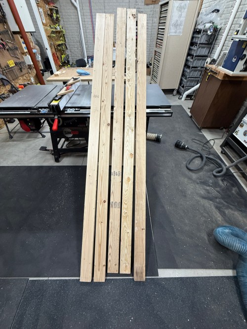
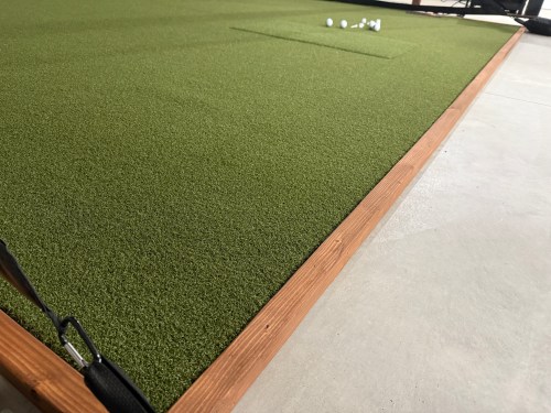
To protect the edges of the turf and hide the base mats, I built a border out of 2x4s ripped down the middle and stained it.
Everything I mentioned was $3,800 and brings the total to $5,650. The third post in this series covers the other electronics and everything else.
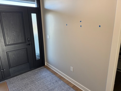
We left our foyer empty in the house design so I could build some things for it.
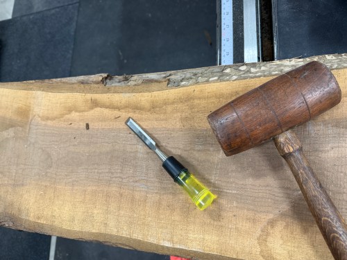
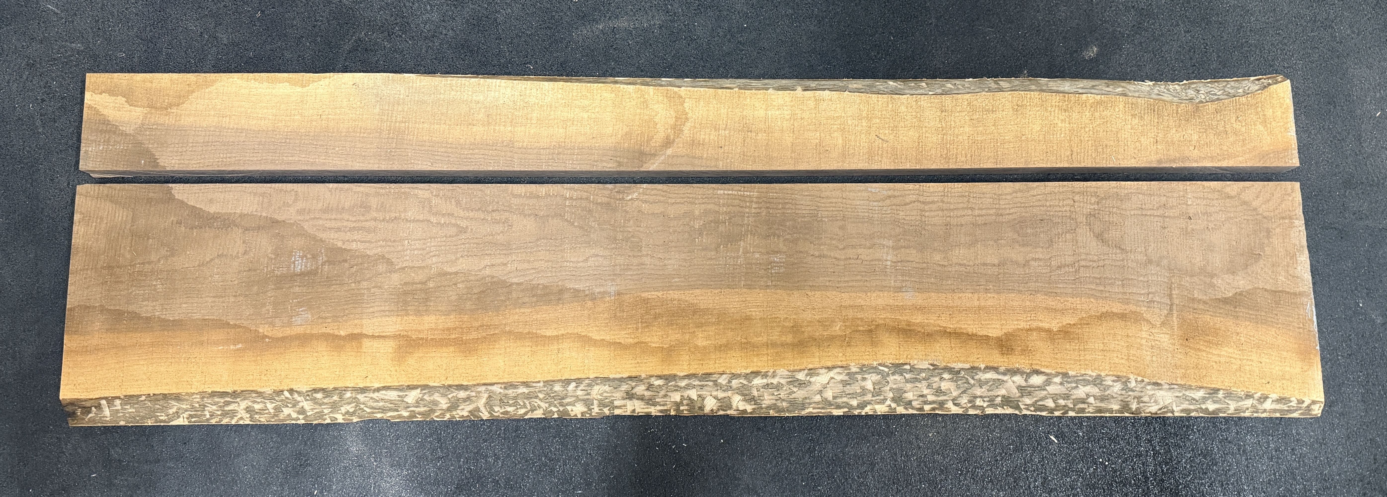
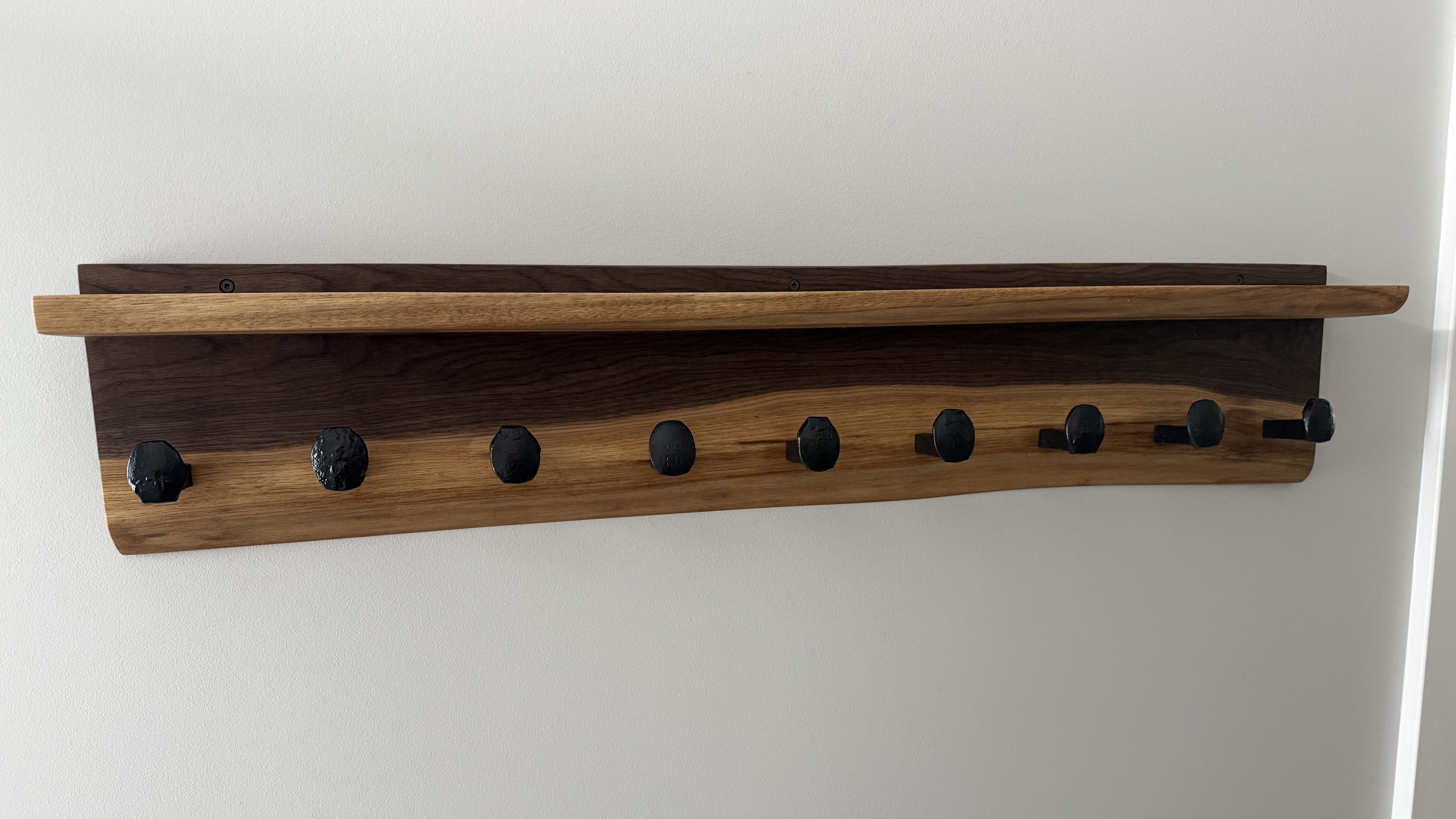
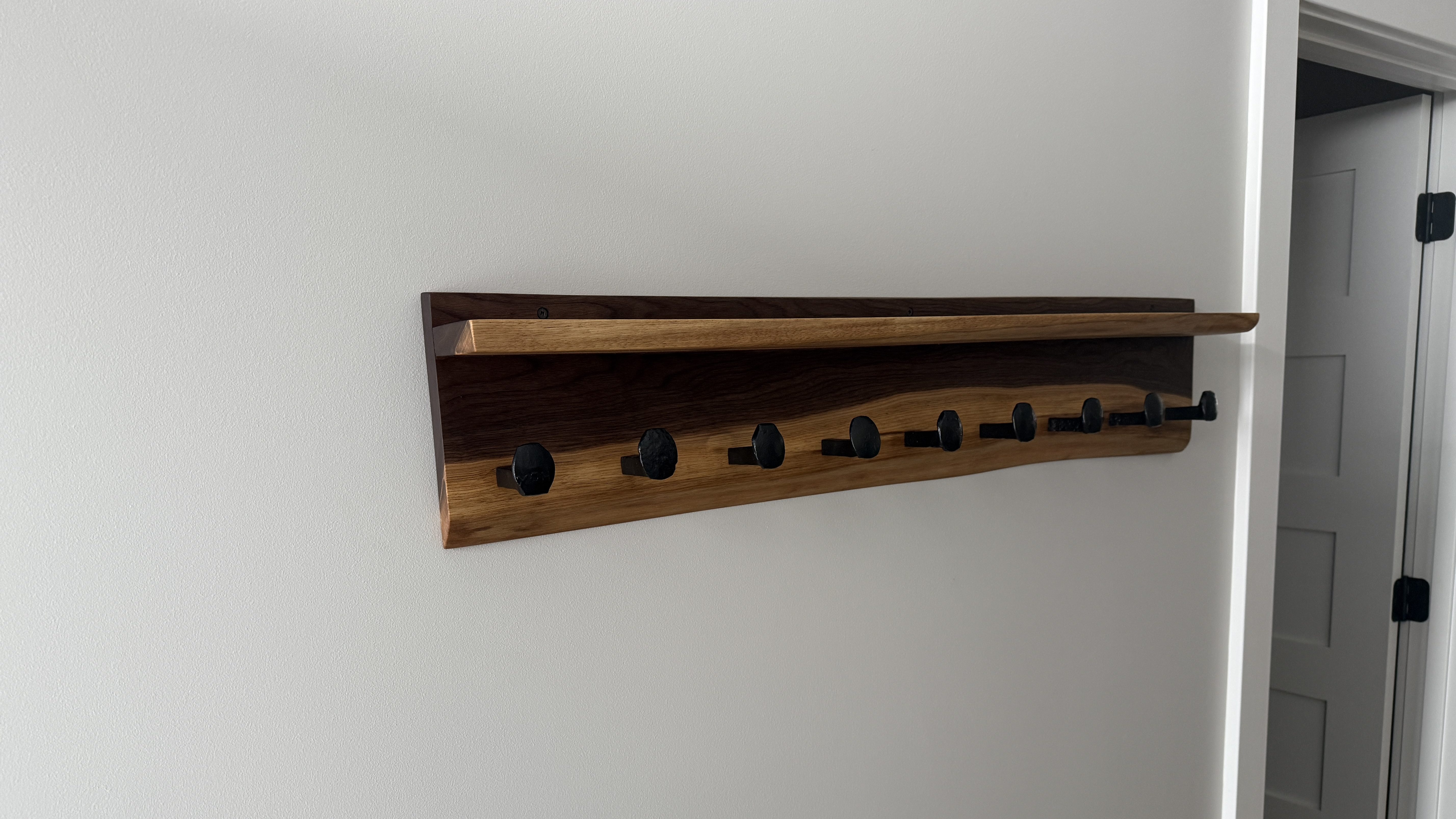
First up was a coat rack. I pulled out a piece of walnut and got the bulk of the bark off the live edge. This piece has a lot of sapwood, which should turn out sweet.
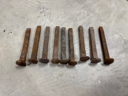
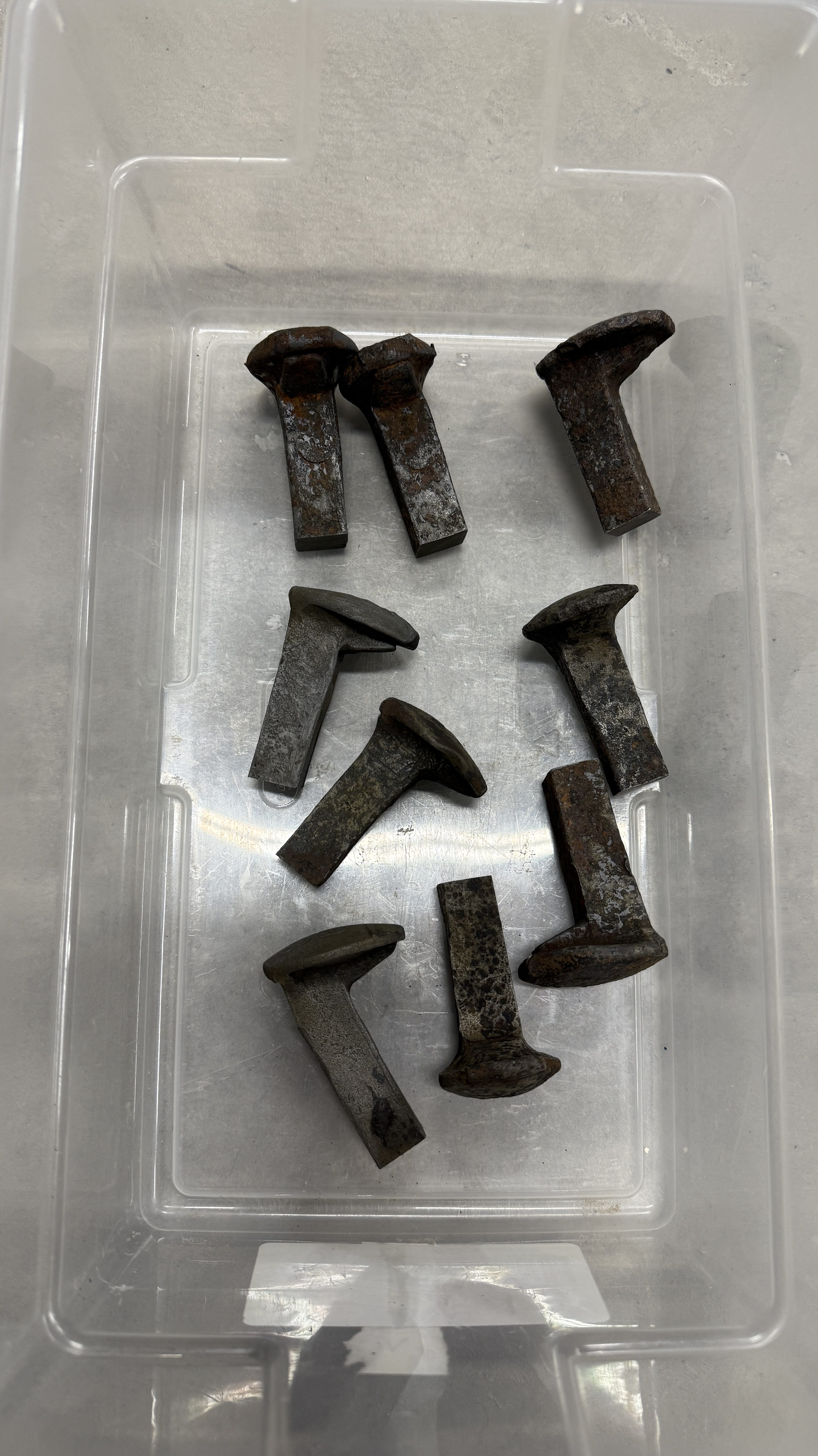
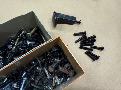
Before getting ahead of myself by sizing the board in any way, I wanted to make the hooks from railroad spikes so I could see how much space they’d need. I bought about 20 of these on Facebook Marketplace a few years ago and still have a bunch.
I don’t have much for metal working tools, so I knew I wouldn’t be able to get consistent length by cutting with an angle grinder. In order to give myself a decent chance at success, I screwed a couple pieces of plywood to my drill press vise and drew a reference line. Then I cut all nine spikes.
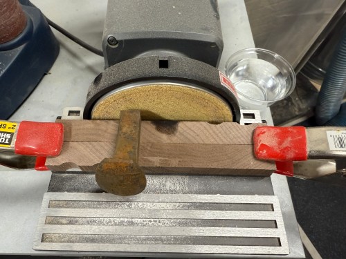
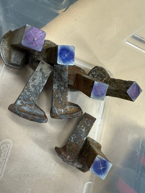
At the disc sander I flattened the ends. For the spikes to lay square to the sanding surface I propped them up on some wood.
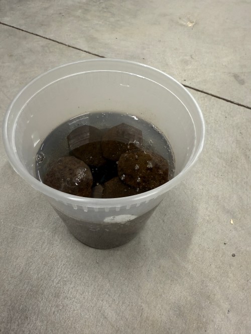
I soaked the pieces in a 50/50 mix of white vinegar and water overnight.
Rinsed and wiped them off.
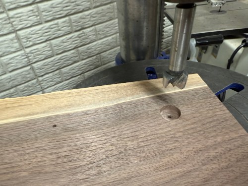
Marked the centers as best I could. Then I stepped through 3/32, 5/32, and 13/64 drill bits on each part. I broke one 3/32 bit and luckily it was deep enough in the hole where it wouldn’t matter.
Then came my favorite part, adding threads in the holes. I used a 1/4-20 tap.
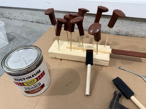
I cleaned up the rest of the rust on a bench grinder wire wheel. Then primer and paint.
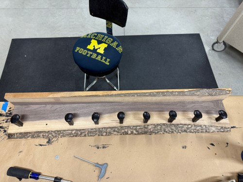
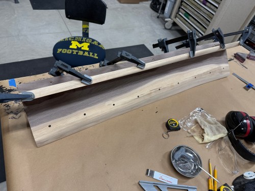
Back to the wood. After doing a rough mockup, I cut a length of the larger board and ripped it to create pieces for the shelf and main.
Then they went through the planer.
Drilled a bunch of holes, found some bolts in my collection, and did a dry fit.
I applied three coats of the All-Natural Wood Finish from Bumblechutes mixed 1:1 with Citrus Solvent. It was the first time I’d used this on a project and I’ll definitely be using it more. It went on easy with a foam brush and light sanding with 400 grit between coats. Then to finish it off, one coat of their Bee’Nooba Wax, which I’ve used before.
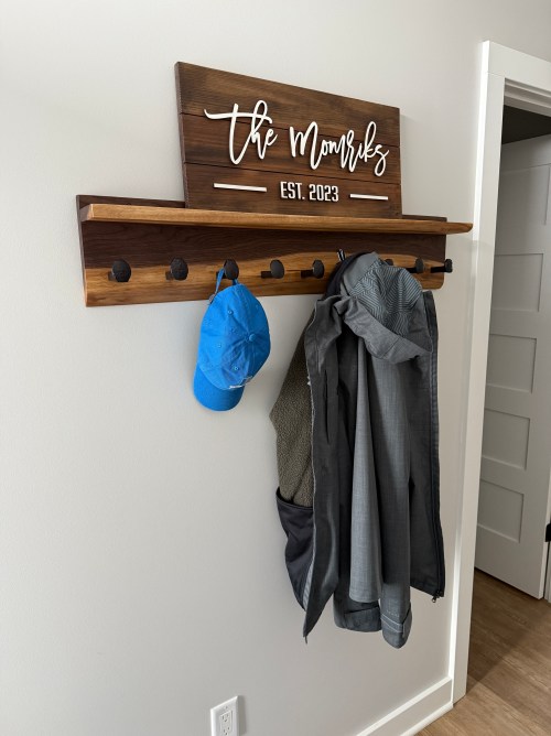
When bolting on the railroad spikes I applied a little thread locker. I mounted it to the wall and put up a sign my sister gave us.
Now I need to figure out what kind of bench to build.
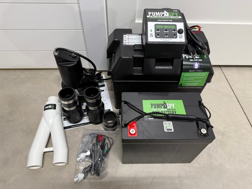
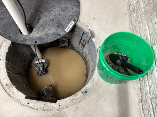
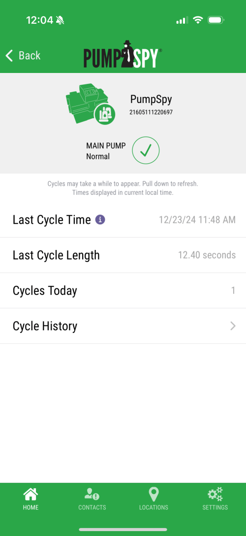
You never know when a long power outage or a malfunction of the float or sump pump is going to result in basement water damage. So it’s a good idea to have some type of backup or early alarm system. Our home builder tried to sell us a proprietary system that costs almost $3,000 and has a yearly $100 subscription fee. The system is only sold to this particular builder, which seemed sketchy, and doesn’t have any API access to the data.
I found PumpSpy, which is a Kalamazoo, Michigan company, because people have been able to integrate the data in to Home Assistant. I bought The Installation Bundle, which costs $667.
I took off our cover and cleaned out some of the debris.
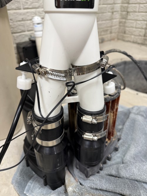
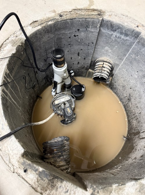
I had to make a minor adjustment to the setup, by splitting the two floats for the backup pump to use separate pipe clamps. With many floats integrated in to the primary sump pump now, it seems like this should be a standard step.
Everything else was smooth sailing by following their installation video and included instructions.
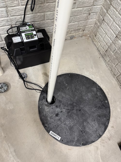
I connected the system to WiFi and setup their iOS app.
I think the entire install took me just over two hours. I love the piece of mind knowing we have a backup system in place.
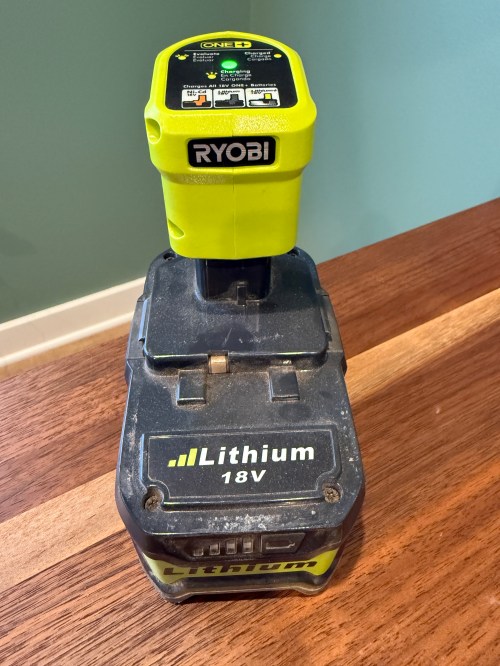
I have a couple of 5 Ah batteries and both of them stopped charging. They knockoffs from Amazon, with a brand name of Biswaye on them.
One was completely dead and wouldn’t even register on a usual charger. The other showed a defective status. When I put the multimeter on, it read about 15 volts.
This often means some of the individual cells are bad. Before opening it up, I threw it on a Ryobi P119 slow charger, which can sometimes revive cells that are too low for the more complex battery chargers.
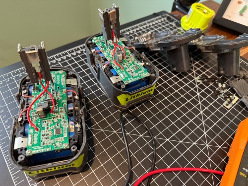
After a couple of hours I tried the battery on a regular charger again, but it still showed as defective. So I tore into both batteries, hoping I might be able to get one working battery out of the two.
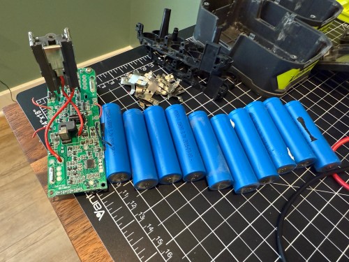
On the dead battery all 10 cells read zero volts on the multimeter. I wouldn’t be swapping any of those in to the other battery. It’s not safe to try pumping anything into cells depleted that much, so I recycled them at Batteries Plus.
Two of the cells on the defective battery read very low voltages. I don’t have any spare 18650 lithium ion cells and it’s not worth it to buy some since I have enough working Ryobi batteries in my rotation. As a last resort, I put the battery on the little charger to see if it would slowly charge the depleted cells. I had nothing to lose.
I let it go over 6 hours and unfortunately the voltage didn’t jump up on those bad cells, so I still can’t use the battery pack.
Attempts like this don’t always end in success, but it’s a fun opportunity to learn. This battery pack has plenty of good cells, so I’ll save it in case another battery needs replacement cells.
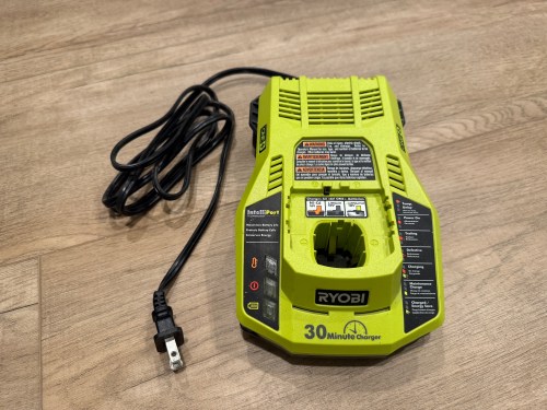
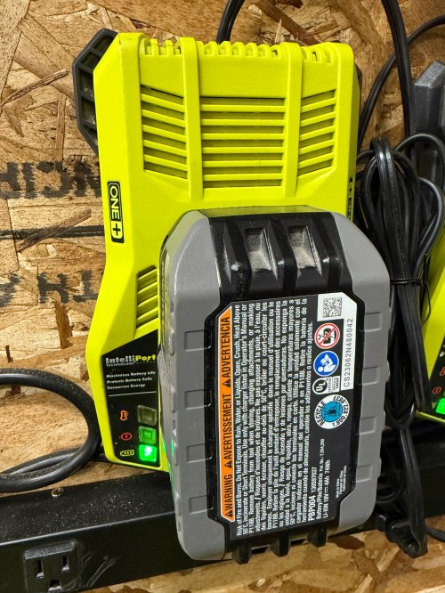
Last week while cutting some walnut with my Ryobi track saw, it kept stalling on me. Turns out the battery was nearly dead because the charger stopped working and the status LEDs weren’t lighting up at all when plugged in.
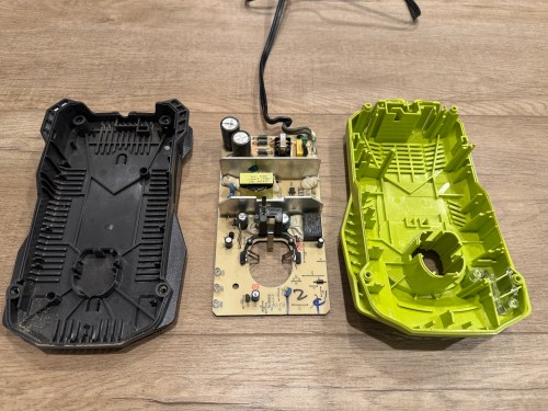
I opened up the charger and didn’t see burn marks or swollen capacitors anywhere.
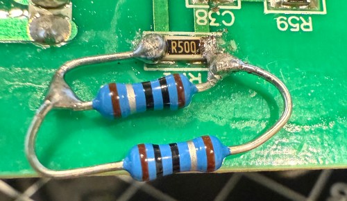
Then I found a video on YouTube and sure enough, the resistor at R71 was wide open, reading 152 kΩ on the multimeter.
It’s a surface mount resistor labeled R500, which means 0.5 Ω. I don’t have any resistors that size, so I soldered in a couple of 1 Ω resistors in parallel.
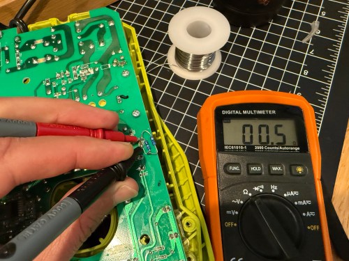
It’s not pretty, but it properly read 0.5 Ω on the multimeter.
I put it back together, plugged it in, and the red LED lit up. Took it down to the shop, put a battery in, and the charger is back in the rotation!