This summer, I got an idea to build some stuff to make an escape room for our family vacation. I finally dismantled some of the parts this week, so I figured it was time to write a post about it and at least get something online in case it’s useful to someone else. I won’t got into much detail here because I think it’s a fun process to think about how you want things to work and learn going through that if you decide to build something similar. The GitHub repo has all of the code, wiring diagrams, and documents. In the docs folder there are things to print for props, some of my notes, and the story.
First, a few lessons I learned when I watched 2 small groups of my family try to escape:
- All of your clues and hints are probably twice as hard as you think.
- People will break shit even if you tell them to be very careful. Hot glue isn’t the best to hold some of this stuff together.
- They’ll think everything is a clue.
My room consisted of 9 different circuits.
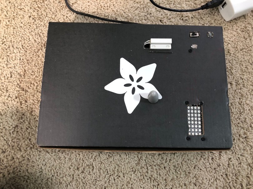
Door Lock
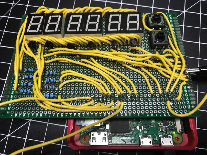
Served as an alarm when telling the story, the game timer, and where participants enter the final code to escape the room. This box is the final build and I the video shows some of the early testing.

Control Panel 1
In order to get things going, a simple switch on the side turns on the first part of the game. When the correct code is entered, it flips a relay module, which then provides power to the rest of the circuits on the control panel. When I built this, I wrote posts about multiplexing 7 segment displays and solder bridges.

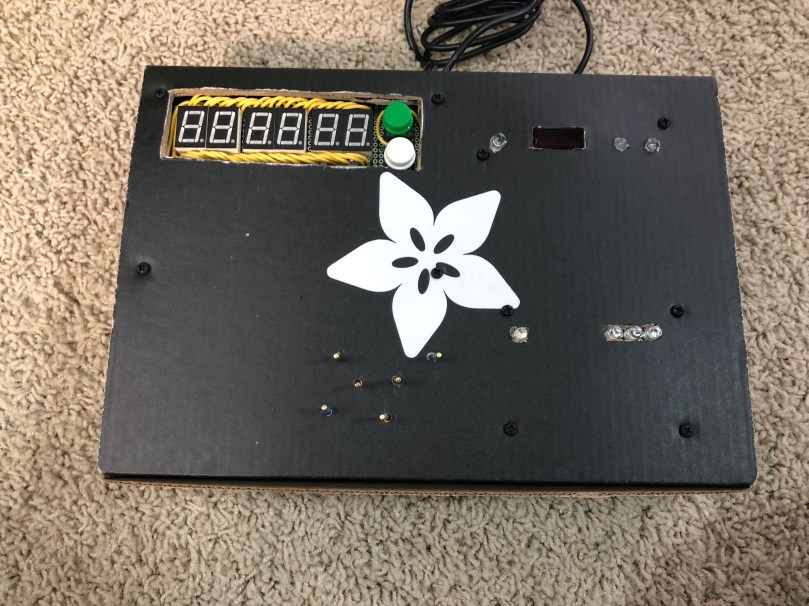
This box also housed control panels 2 & 3, which I talk about below.
Power Outlet Relay
I wrote a few posts about building the relay module for this. There are also plenty of guides online.

Control Panel 2
Basically some colored wires that needed to be connected in the correct order. Not that easy to see in the pictures above but it’s the bottom part of the box with the 6 standoffs sticking up out of the box, the single LED, and the group of 3 LEDs.
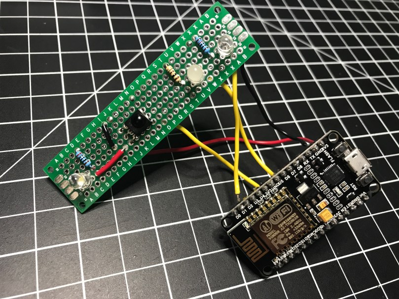
Control Panel 3
An infrared receiver. After finding batteries for an old VCR remote, when the correct button was pressed, a colored LED would blink a number of times. It’s the top right section of the box above.
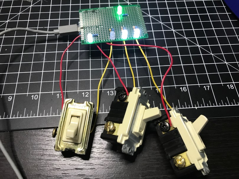
Control Panel 4
Used 3 old light switches as binary on/off. When the switches were set correctly the binary to decimal conversion gave part of the code and the color of the LED gave another part.


Control Panel 5
I used the keypad I got out of an old phone, which I wrote a 4 part series about. I learned a lot and had some fun figuring that stuff out.


This went in the same box as control panel 4.
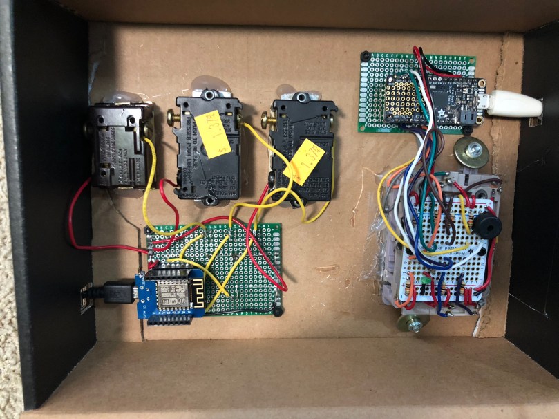

Control Panel 6
Probably the most confusing part for participants to figure out. It consisted of:
- A knob which needed to be rotated to the correct general position.
- A light sensor which needed to have a flashlight (find batteries) pointed at.
- A distance sensor on the side which needed to have an object a certain distance away.
- A sensor which need to have a magnet near by.
As feedback, there was an LED matrix used as a bar graph. Once a sensor was set properly the line would fill up and a buzzer would beep. When all 4 things were set correctly at the same time, the LED matrix would scroll some text across it, providing the necessary code.


Circuit Playground
Taking advantage of the accelerometer on this microcontroller, the goal here was to tilt the board in a series of directions within a short period of time. The LEDs and buzzer on the board were used for feedback. With a win, the board would give audio and visual feedback in the form of another code to be used with the door lock. The period of time was way too short for people.
The Door Code
Each circuit that provided an answer/clue was a combination of a color and a number. These needed to be matched up with the colors being in the correct order and then the numbers would unlock the door. In order to figure out the correct order, a series of index cards with cutouts needed to be arranged properly (by matching symbols in the corners of the cards) so the “windows” would show the names of colors.

Summary
If I were to do it again, I’d know that there is way too much going on here and to make it much easier. I had a lot of fun building all of the circuits, writing the code, and trying to figure out how people would interact with the different parts.
I know everything here is a bit light on details, but that’s on purpose. I didn’t even mention the other props I had in the “room” to go along with this stuff. If you decide to build something similar hopefully this stuff will give you some ideas to can run with. Leave a comment if you have any questions.

[…] has an infrared (IR) remote and the light has a radio frequency (RF) remote. I’ve done some things with IR and still had a stash of IR LEDs (for transmitting) and receivers. I’ve never […]
LikeLike