One of our daily tasks is to clean out the cat litter boxes and we (on maybe I just wanted an excuse to automate part of the process!) run in to a couple of small problems:
- We usually don’t know if the other has already cleaned them.
- We obviously don’t want to forget.
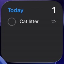
- Since I primarily took over this job, I’ve been using a daily reminder, but it’s on my iPhone nagging me all day, even though it’s set for noon. I only need a reminder when it doesn’t get done.
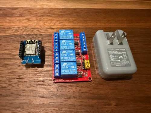
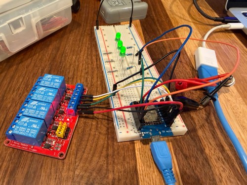
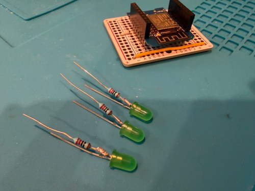
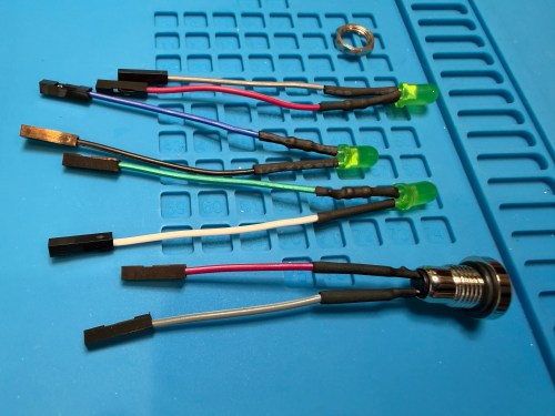
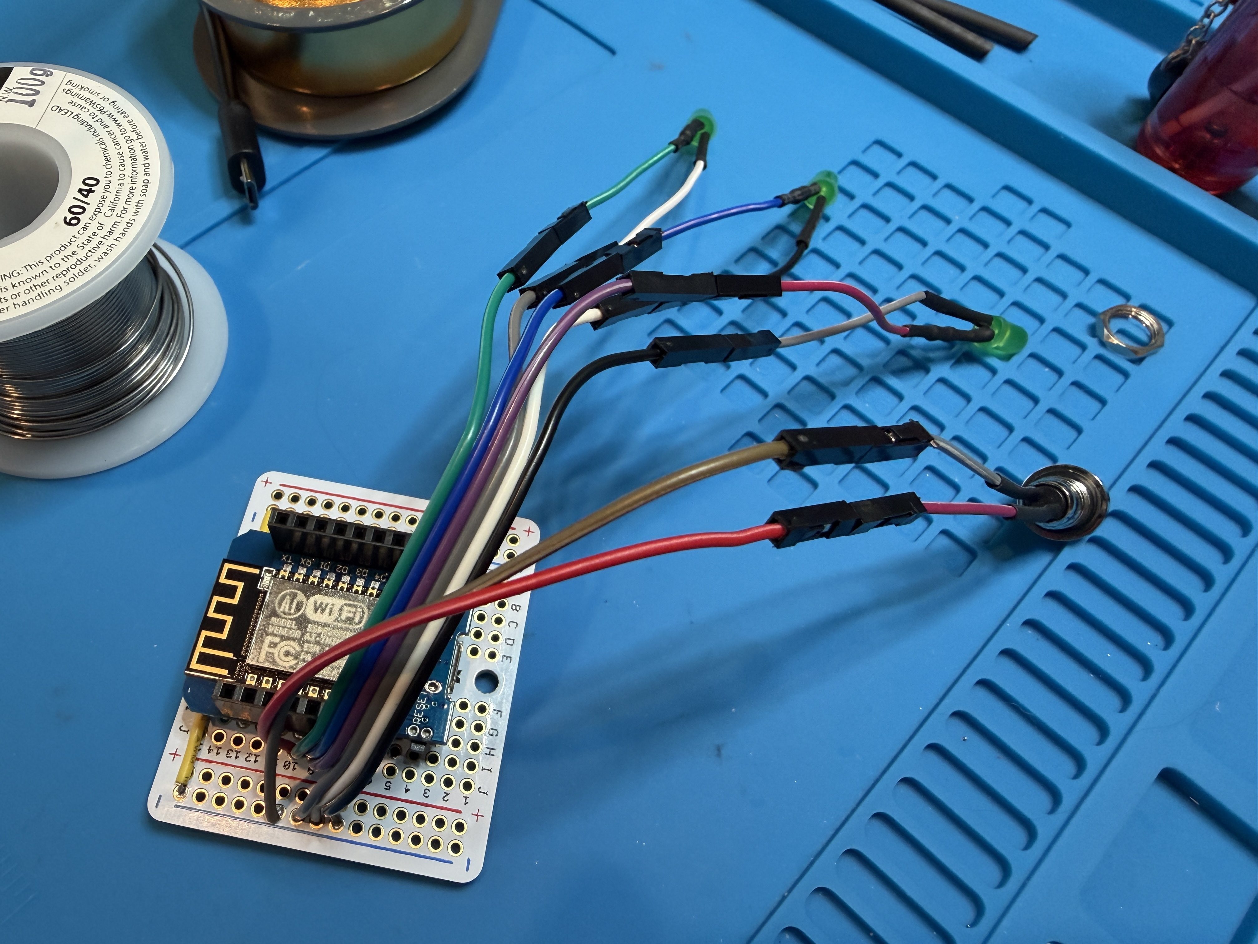
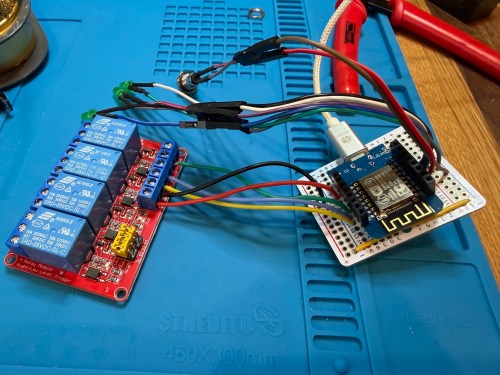
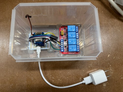
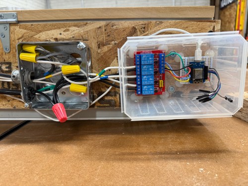
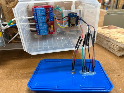
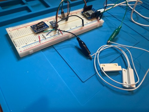
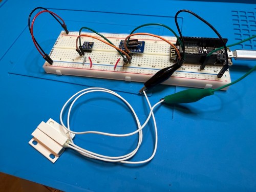
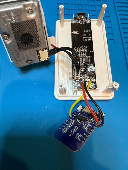
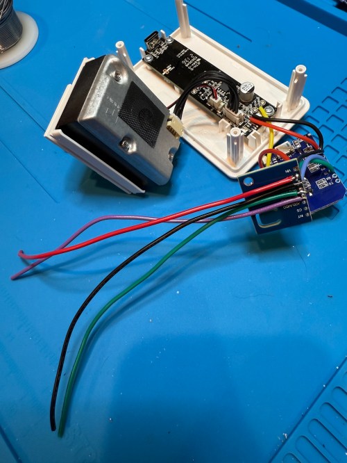
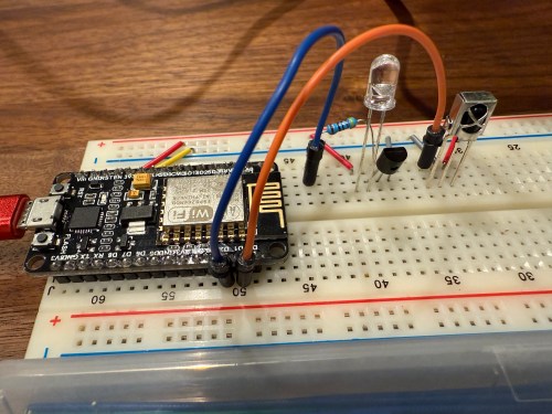
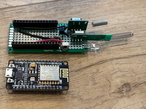
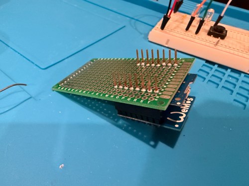
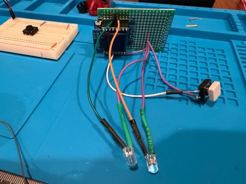
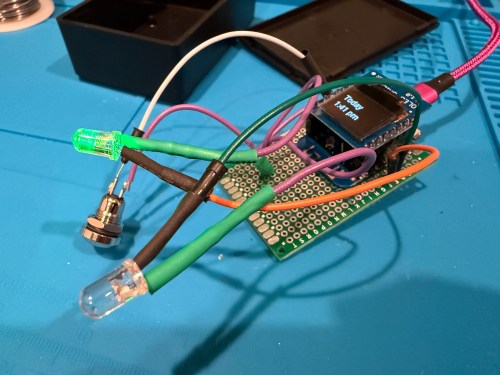
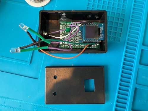
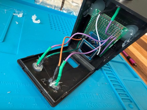
I thought of a solution with an ESPHome based device and Home Assistant. I used a WEMOS D1 Mini Lite, WEMOS OLED Shield, button, red LED, green LED, and 220 Ohm resistors. I connected everything on a breadboard for testing and then made it more permanent.
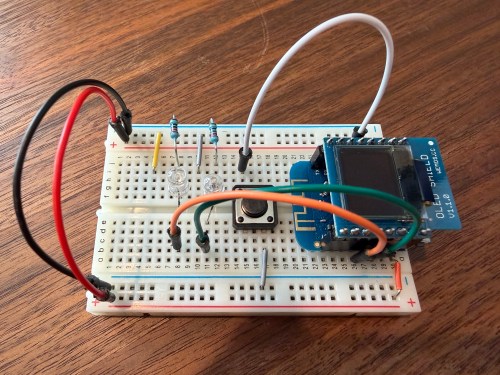
Key functionality:
- During the day, the green LED will be lit if the litter boxes have been cleaned and the red LED if they need to be cleaned. If we’re walking by, green means keep going and red means stop here.
- At night (8pm to 8am), the LEDs are off, unless the device is woken up.
- Press the button to turn on the display and status LED if at night. The display shows the last time the litter was cleaned in one of three formats, depending on how long it’s been.
- Today
1:23 PM - Yesterday
2:48 PM - 2 days ago
11:00 AM
- Today
- Press the button when the display is on to update the litter box last cleaned date and time. The LEDs flash to signify something is happening. The new date and time gets shown on the display.
- After 30 seconds the display turns off.
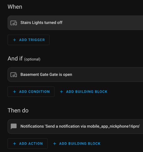
- At 4pm send a reminder to our phones if the litter boxes need to be cleaned.
- In Home Assistant a toggle can disable the reminders. Useful when we’re on vacation.
Here’s the ESPHome device YAML:
substitutions:
  device_name: cat-litter
  api_key: !secret catlitter_api
  ota_password: !secret catlitter_ota
  ip_address: !secret catlitter_ip

packages:
  base: !include z_package_base.yaml

esphome:
  name: ${device_name}
  friendly_name: Cat Litter
  on_boot:
    priority: 800
    then:
      - lambda: |-
          id(cat_litter_display).turn_on();
          id(screen_is_active) = true;
      - component.update: cat_litter_display
      - script.execute: display_timer

esp8266:
  board: d1_mini_lite

globals:
  - id: screen_is_active
    type: bool
    restore_value: no
    initial_value: 'true'

# WEMOS OLED Shield
i2c:
  sda: GPIO4
  scl: GPIO5
  scan: true
  id: bus_a
  frequency: 100kHz

time:
  - platform: homeassistant
    id: esptime
    on_time:
      - seconds: 1
        minutes: 0
        hours: 8
        then:
          - script.execute: update_led_logic
      - seconds: 1
        minutes: 0
        hours: 20
        then:
          - script.execute: update_led_logic

font:
  - file: "fonts/Roboto-Regular.ttf"
    id: roboto_font
    size: 12

text_sensor:
  - platform: homeassistant
    id: litter_text
    entity_id: sensor.cat_litter_status_formatted
    on_value:
      then:
        - component.update: cat_litter_display
        - script.execute: update_led_logic

binary_sensor:
  - platform: homeassistant
    id: remote_litter_status
    entity_id: binary_sensor.litter_needs_cleaning
    on_state:
      then:
        - script.execute: update_led_logic

  # Physical button
  - platform: gpio
    pin:
      number: GPIO0
      inverted: true
      mode: INPUT_PULLUP
    name: "Cleaned Button"
    filters:
      - delayed_on: 50ms
    on_press:
      then:
        - if:
            condition:
              lambda: 'return !id(screen_is_active);'
            then:
              # WAKE UP
              - lambda: |-
                  id(cat_litter_display).turn_on();
                  id(screen_is_active) = true;
              - component.update: cat_litter_display
              - script.execute: update_led_logic
              - script.execute: display_timer
            else:
              # TRIGGER CLEANED
              - delay: 50ms
              - homeassistant.service:
                  service: script.cat_litter_cleaned
              - script.execute: led_flash_animation
              - script.execute: display_timer

output:
  - platform: esp8266_pwm
    pin: GPIO14
    id: led_green
  - platform: esp8266_pwm
    pin: GPIO12
    id: led_red

script:
  - id: update_led_logic
    then:
      - lambda: |-
          if (!id(remote_litter_status).has_state()) return;

          auto time = id(esptime).now();
          bool is_night = false;
          if (time.is_valid()) {
            is_night = (time.hour >= 20 || time.hour < 8);
          }

          if (id(cat_litter_display).is_on()) { is_night = false; }

          if (is_night) {
            id(led_red).turn_off();
            id(led_green).turn_off();
          } else {
            if (id(remote_litter_status).state) {
              id(led_red).set_level(0.2);
              id(led_green).turn_off();
            } else {
              id(led_red).turn_off();
              id(led_green).set_level(0.2);
            }
          }

  - id: display_timer
    mode: restart
    then:
      - delay: 30s
      - lambda: |-
          id(cat_litter_display).turn_off();
          id(screen_is_active) = false;
      - script.execute: update_led_logic

  - id: led_flash_animation
    mode: restart
    then:
      - repeat:
          count: 5
          then:
            - output.set_level: { id: led_green, level: 0.3 }
            - output.turn_off: led_red
            - delay: 150ms
            - output.turn_off: led_green
            - output.set_level: { id: led_red, level: 0.3 }
            - delay: 150ms
      - script.execute: update_led_logic

display:
  - platform: ssd1306_i2c
    id: cat_litter_display
    model: "SSD1306 64x48"
    address: 0x3C
    rotation: 180°
    lambda: |-
      if (id(litter_text).has_state()) {
        std::string full_text = id(litter_text).state;
        size_t pos = full_text.find("@");
        if (pos != std::string::npos) {
          std::string day = full_text.substr(0, pos);
          std::string time_str = full_text.substr(pos + 1);
          it.printf(32, 8, id(font_main), TextAlign::TOP_CENTER, "%s", day.c_str());
          it.printf(32, 26, id(font_main), TextAlign::TOP_CENTER, "%s", time_str.c_str());
        } else {
          it.printf(32, 24, id(font_main), TextAlign::CENTER, "%s", full_text.c_str());
        }
      } else {
        it.printf(32, 24, id(font_main), TextAlign::CENTER, "Syncing...");
      }
Some helpers in configuration.yaml:
template:
- binary_sensor:
  - name: "Litter Needs Cleaning"
    unique_id: litter_needs_cleaning
    # This turns ON (Red LED) if the date is not today
    state: >
      {% set last = states('input_datetime.cat_litter_last_cleaned') | as_datetime %}
      {% if last is none %} true {% else %}
        {{ last.date() < now().date() }}
      {% endif %}
- sensor:
  - name: "Cat Litter Status Formatted"
    unique_id: cat_litter_status_formatted
    state: >
        {% set last = states('input_datetime.cat_litter_last_cleaned') | as_datetime %}
        {% if last is none %}
            No Data @ --:--
        {% else %}
            {% set diff = (now().date() - last.date()).days %}
            {% set time = last.strftime('%-I:%M %p').lower() %}
            {% if diff == 0 %}
                Today @ {{ time }}
            {% elif diff == 1 %}
                Yesterday @ {{ time }}
            {% else %}
                {{ diff }} days ago @ {{ time }}
            {% endif %}
        {% endif %}

notify:
  - name: "momrik_phones"
    platform: group
    services:
      - service: mobile_app_nick
      - service: mobile_app_brandi
Automations in automations.yaml:
- id: '1768843528106'
  alias: Notify - Cat Litter @ 4PM
  description: ''
  triggers:
  - trigger: time
    at: '16:00:00'
  conditions:
  - condition: state
    entity_id: binary_sensor.litter_needs_cleaning
    state:
    - 'on'
  - condition: state
    entity_id: input_boolean.cat_litter_reminders
    state:
    - 'on'
  actions:
  - action: notify.momrik_phones
    metadata: {}
    data:
      title: "Cat Litter \U0001F408 \U0001F4A9"
      message: The litter hasn't been cleaned yet today!
      data:
        tag: cat-litter-alert
        actions:
        - action: MARK_LITTER_CLEANED
          title: I did it
  mode: single
- id: '1768843827814'
  alias: Notify Clear - Cat litter
  description: ''
  triggers:
  - trigger: event
    event_type: mobile_app_notification_action
    event_data:
      action: MARK_LITTER_CLEANED
  conditions: []
  actions:
  - action: script.cat_litter_cleaned
    data: {}
  - action: notify.momrik_phones
    data:
      message: clear_notification
      data:
        tag: cat-litter-alert
  mode: single
One script in scripts.yaml:
cat_litter_cleaned:
  alias: "Cat Litter Cleaned"
  sequence:
    - service: input_datetime.set_datetime
      target:
        entity_id: input_datetime.cat_litter_last_cleaned
      data:
        datetime: "{{ now().strftime('%Y-%m-%d %H:%M:%S') }}"
    - service: notify.momrik_phones
      data:
        message: "clear_notification"
        data:
          tag: "cat-litter-alert"
I also added a couple of simpler helpers via Settings -> Devices & services -> Helpers:
- Cat Litter Last Cleaned – Date and time
- Cat Litter Reminders – Toggle
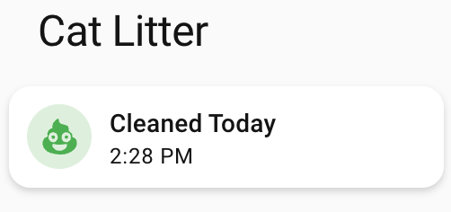
Finally, I added cards to a Home Assistant dashboard. See screenshots of the different states of each card below.
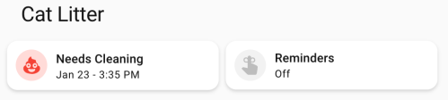
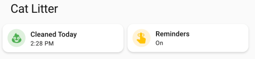
Here’s the dashboard YAML if you want it.
type: horizontal-stack
title: Cat Litter
cards:
  - type: custom:mushroom-template-card
    primary: >-
      {% set last = states('input_datetime.cat_litter_last_cleaned') |
      as_datetime %}

      {% if last is none %}
        Unknown State
      {% else %}
        {% set diff = (now().date() - last.date()).days %}
        {% if diff == 0 %}
        Cleaned Today
        {% else %}
        Needs Cleaning
        {% endif %}
      {% endif %}
    icon: mdi:emoticon-poop
    features_position: bottom
    secondary: >-
      {% set last = states('input_datetime.cat_litter_last_cleaned') |
      as_datetime %}

      {% if last is none %}

      ???

      {% else %}
        {% set diff = (now().date() - last.date()).days %}
        {% if diff > 0 %}
          {{ last.strftime('%b %-d') }} -
        {% endif %}
        {{ last.strftime('%-I:%M %p') }}
      {% endif %}
    color: |-
      {% if is_state('binary_sensor.litter_needs_cleaning', 'on') %}
        red
      {% else %}
        green
      {% endif %}
    tap_action:
      action: more-info
    icon_tap_action:
      action: perform-action
      perform_action: script.cat_litter_cleaned
      target: {}
      confirmation:
        text: Are you sure you want to update the last cleaned date/time to now?
    entity: input_datetime.cat_litter_last_cleaned
  - type: custom:mushroom-entity-card
    entity: input_boolean.cat_litter_reminders
    name: Reminders
    tap_action:
      action: toggle
    hold_action:
      action: more-info
    icon_color: amber
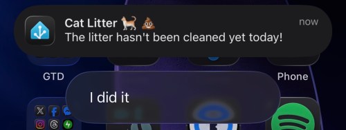
If we get a reminder, it looks like this. We can click I did it to update the date/time to now if we forgot to press the button on the physical device. With the automation set to run at 4pm, we should rarely see this though.
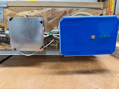
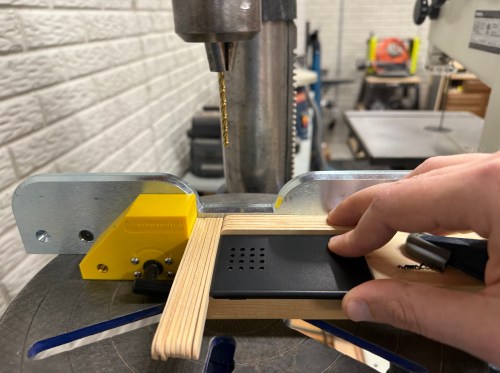
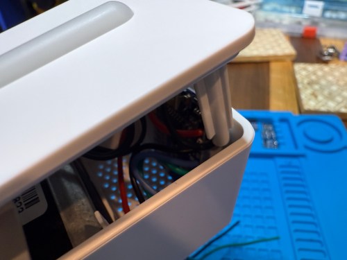
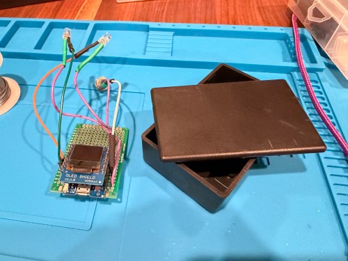
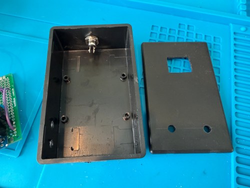
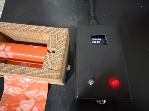
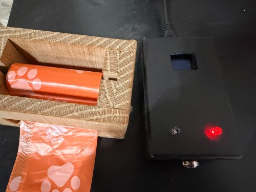
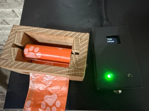
The final device lives right next to the waste bag dispenser I made. This way it’s easy to see the state and hit the button when cleaning out the litter. Here are photos in place with a few different states.
This project was so fun. Using Google Gemini for stuff like this makes it so much faster. I’ve had some of these microcontrollers and other parts for almost a decade so it’s nice to finally put them to use.
What other features or automations would you add to this? Have you built anything similar?