Time to finish this table. While part 1 and part 2 were quite involved, the rest was all about drawers. I needed to make use of the rest of the space inside the table.
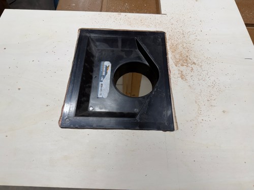
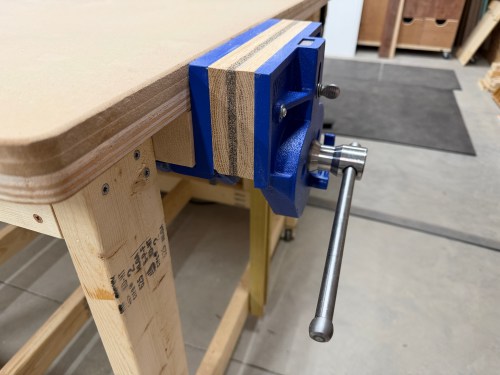
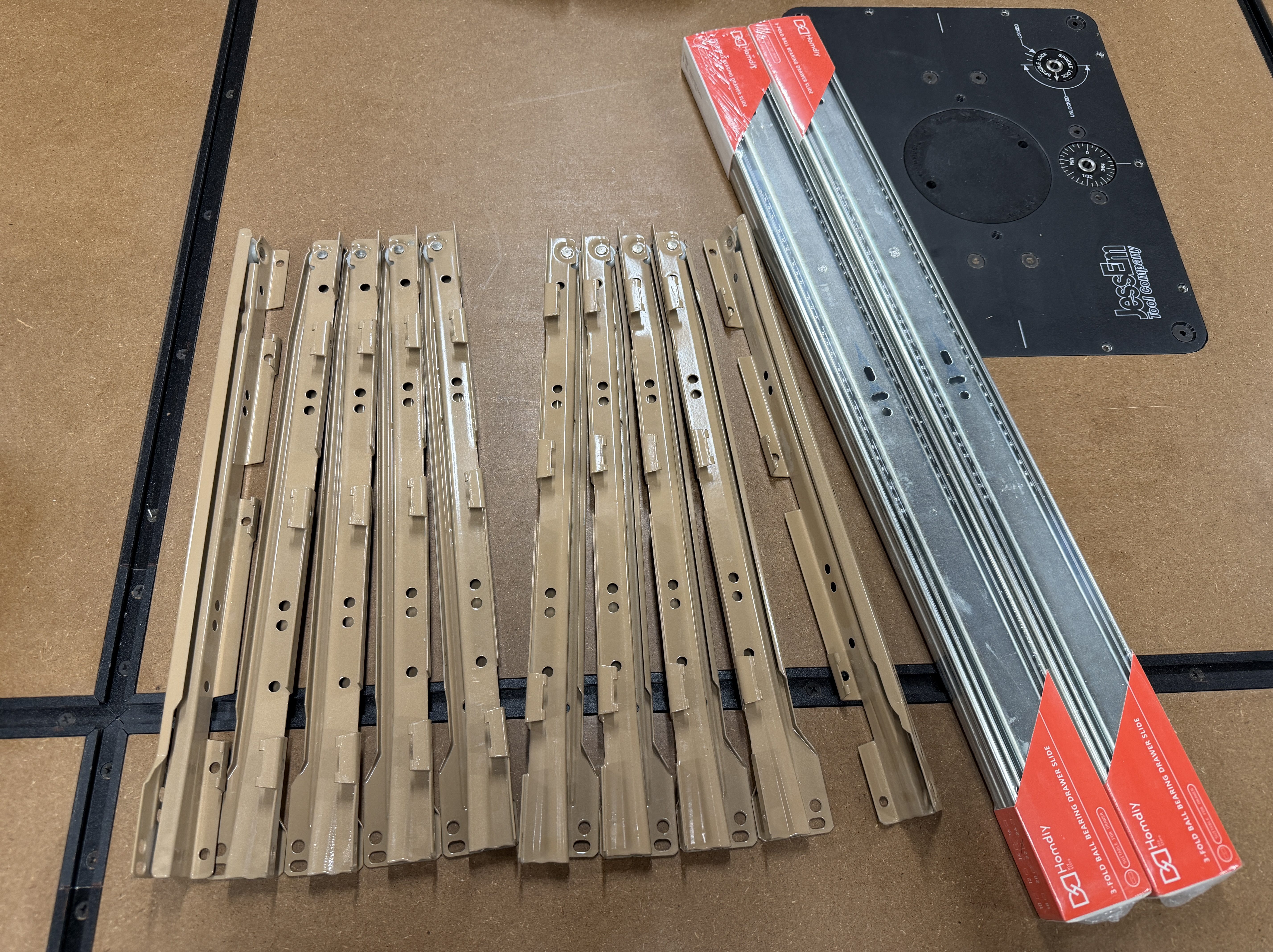
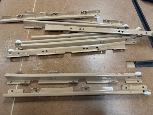
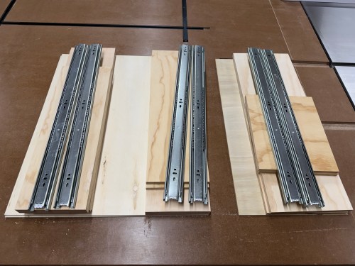
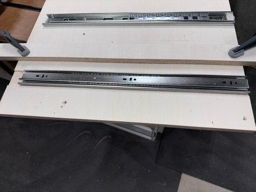
First, I got to work on a cabinet next to the router station, on the front of the table. I wanted to use five sets of cheap drawer slides I salvaged from an old dresser. I had enough room for four deeper drawers, using 22″ slides. I took measurements and sketched out a plan. I had to design around the vice, which hung down below the frame of the table.


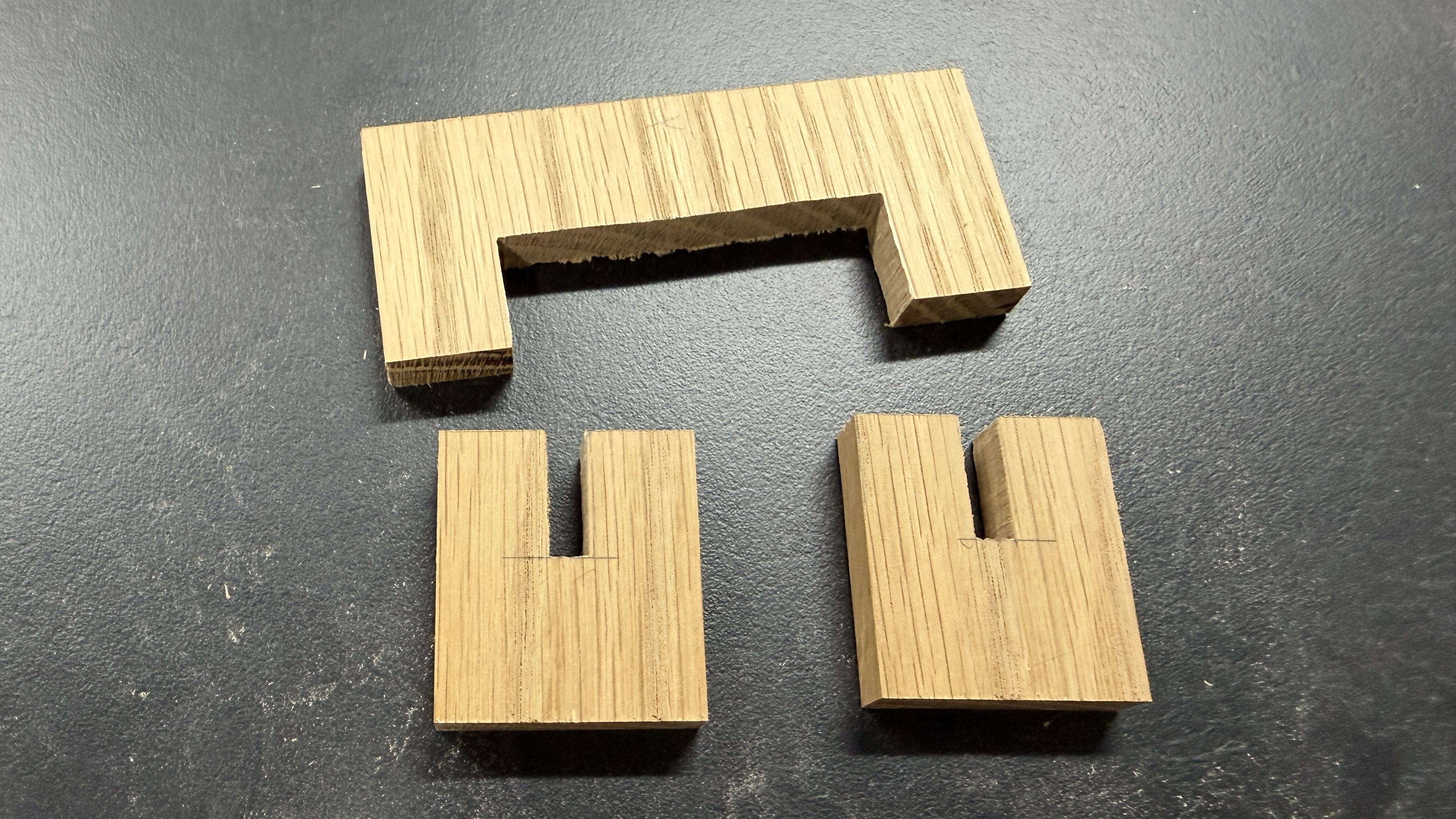
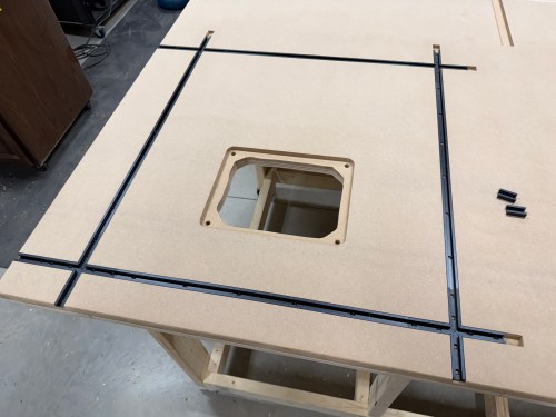
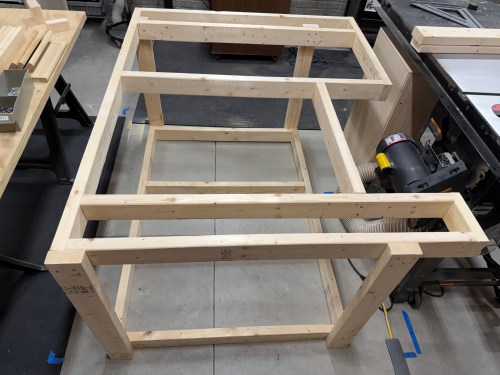
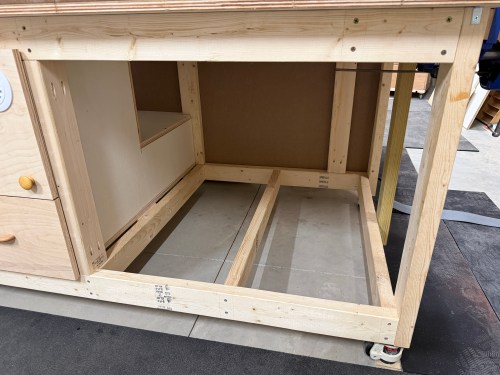
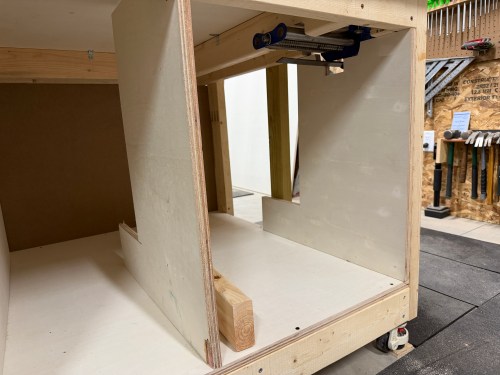
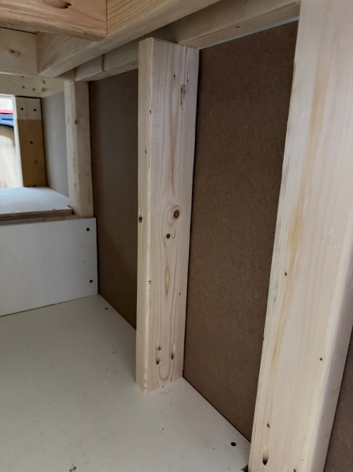
I cut a full bottom panel and some 2x4s for extra bracing. I wanted to make good use of space and have the most room for drawers on the right side of the table, so the vertical supports were made in the odd L shape again. The one on the left was cut to match up with the one from the router station.
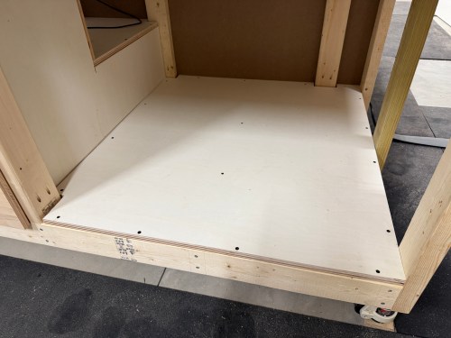
In the middle, I needed something up top to connect to, so I cut a piece of 2×4 and would secure it in place after determining the exact width of the left drawer column. The vertical on the right needed some cut away around the vice.
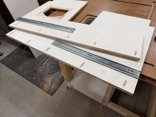
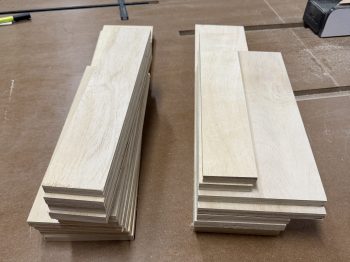
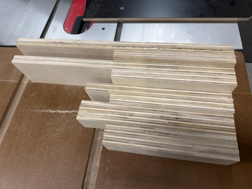
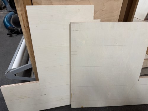
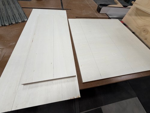
Then I was able to cut all of the drawer sides, with two different depths for the different types of slides I was using. Or so I thought.
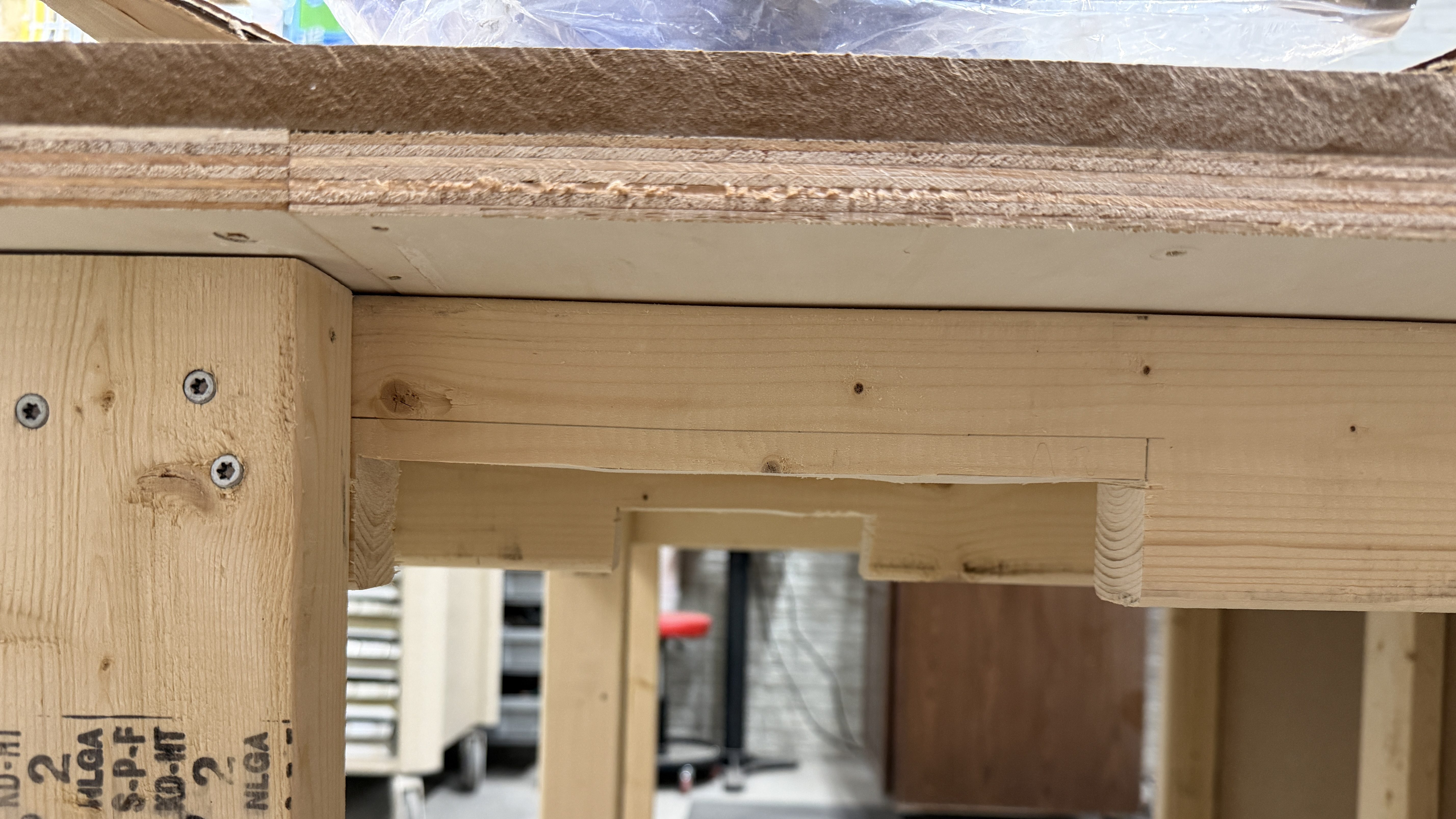
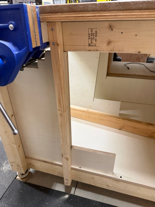
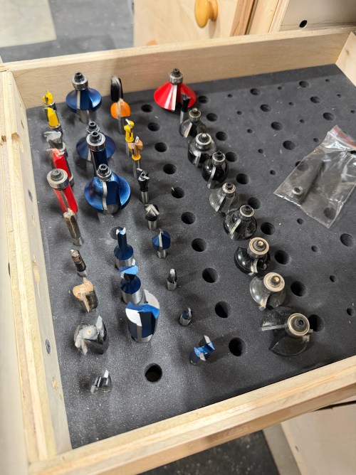
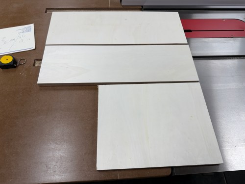
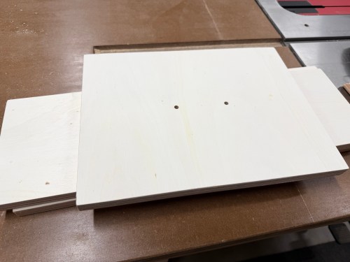
As I was going over some of my notes I realized I didn’t cut the back part of the middle and right verticals tall enough. To fix the mistake, I glued and pocket screwed on some patch pieces. I also had to recut longer sides for two drawers. From there I figured out the width of the left drawers based on the foam router bit storage tray I was using. Then I cut the fronts, backs, and bottoms for the five left drawers.


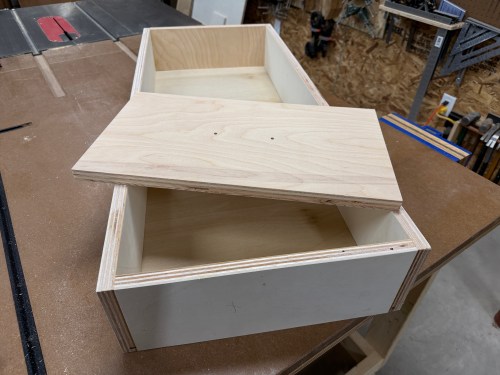
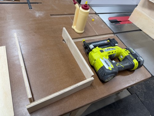
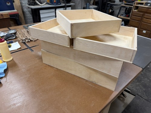
Assembly was quick with glue and brad nails.
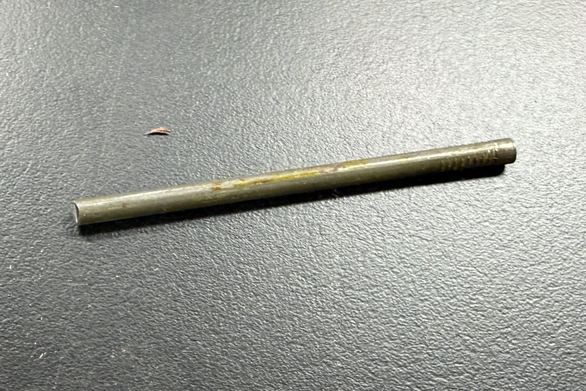
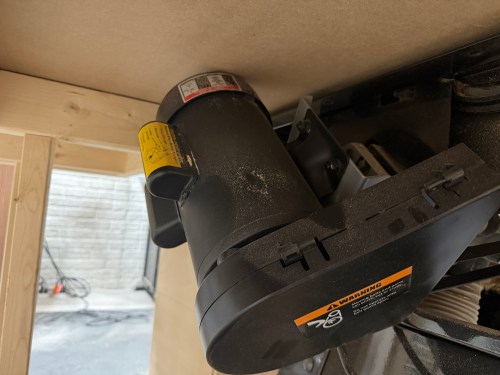
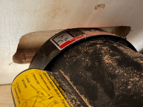
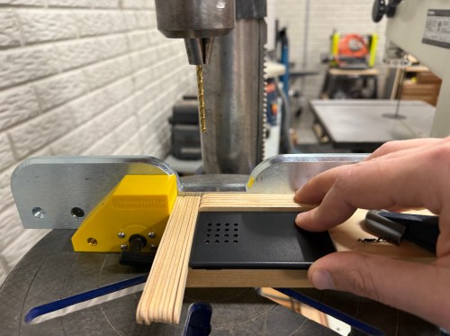
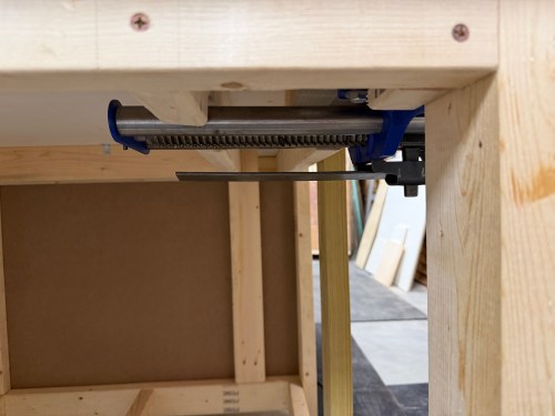
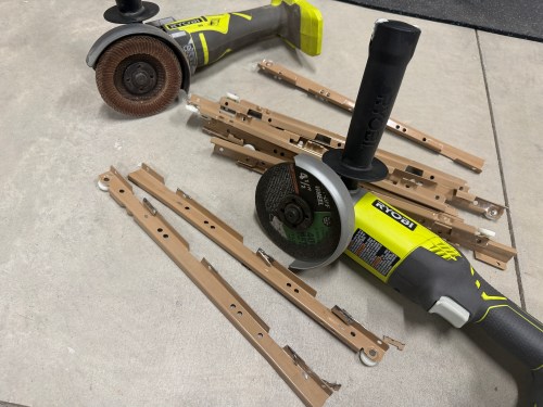
I modified the old drawer slides with an angle grinder to remove tabs that were in the way for my use case.
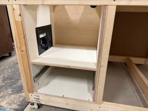
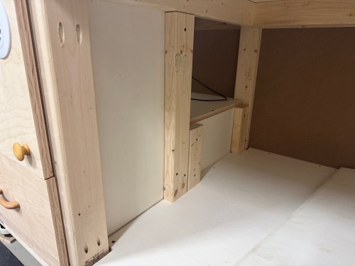
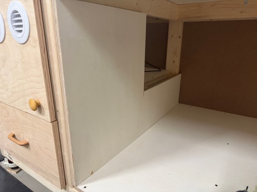
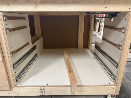
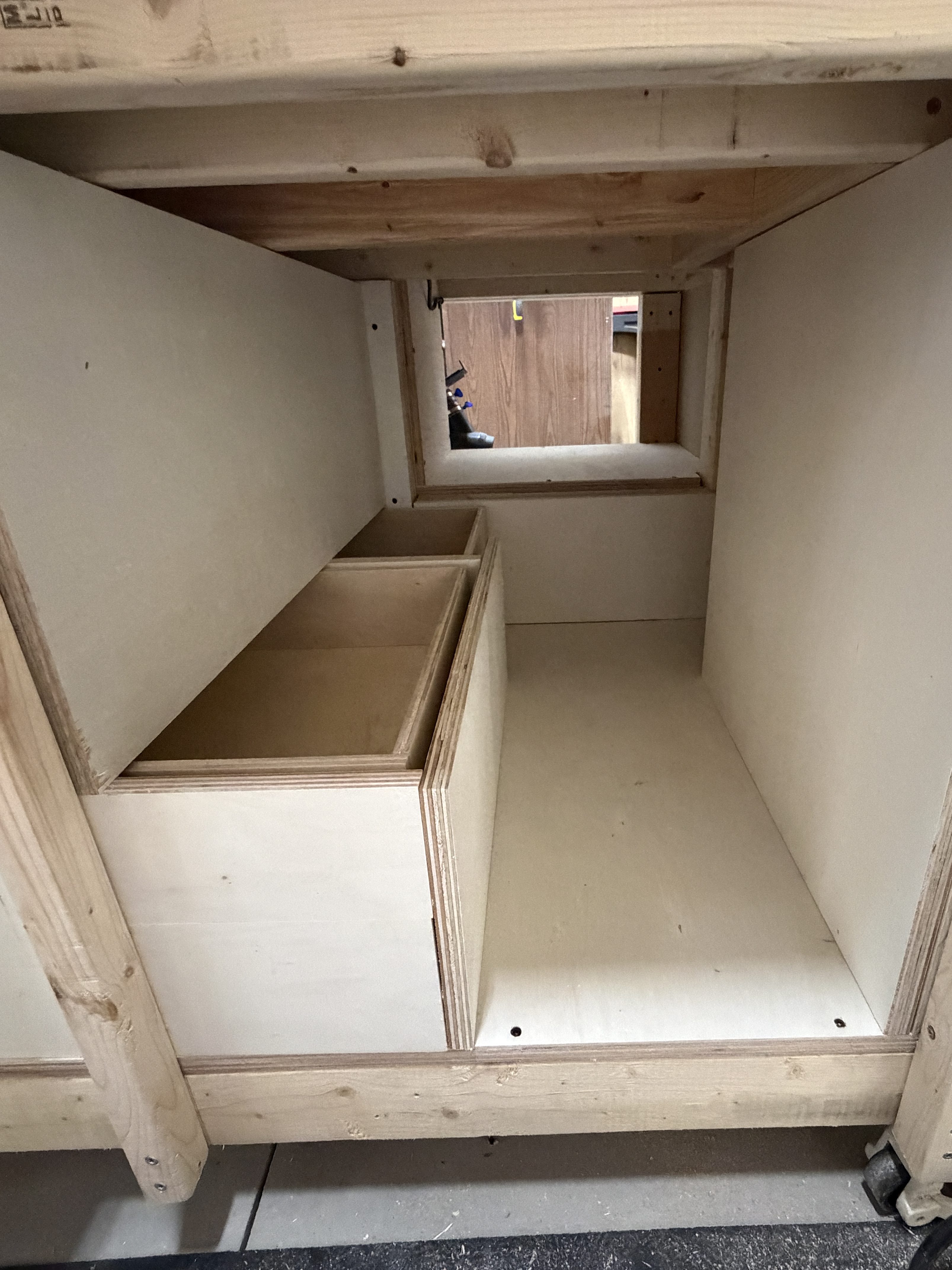
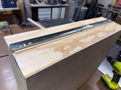
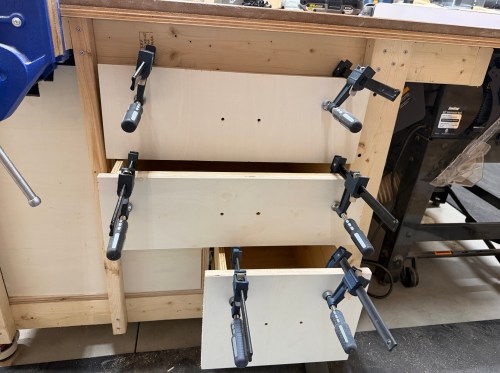
I mounted the slides to the verticals for both columns of drawers. Then I was able to secure the left and right verticals to the table frame, attach slides to the left drawers, and put them in to guide the placement of the middle vertical. It got screwed in, along with the upper 2×4.


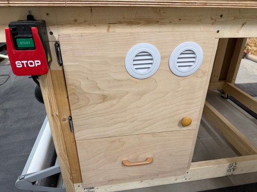
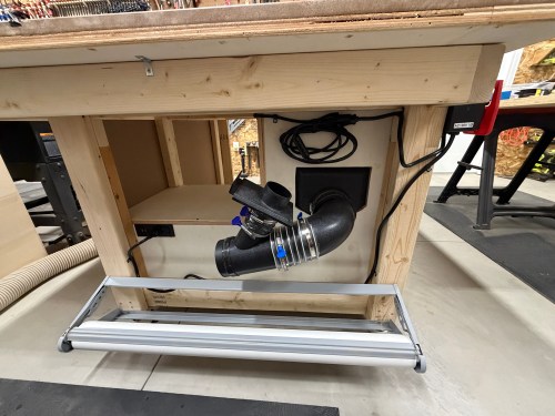
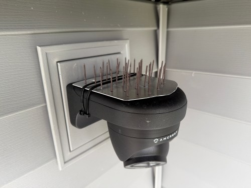
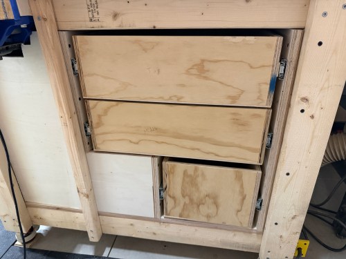
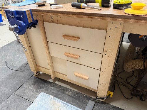
With the left column of drawers in, I figured out how wide the remaining parts needed to be for the right column of drawers and got them done. Then it was time for some drawer fronts and a false front, since the vice prevented a drawer from being installed there. This gave me a place for a recessed power strip with USB. I didn’t have enough matching handles, so I used two different styles I’ve bought at estate sales.


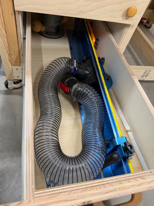
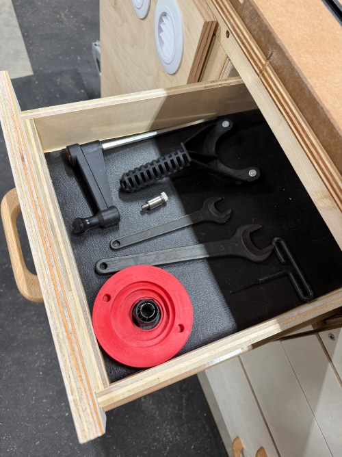
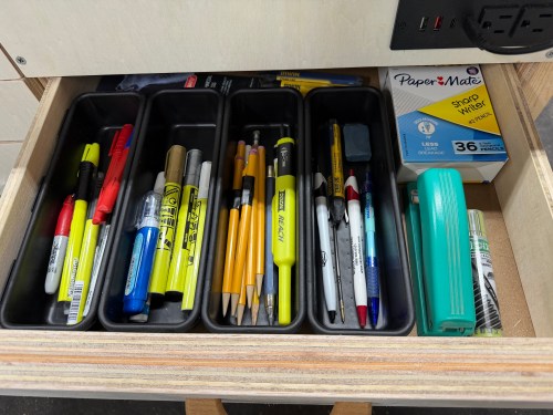
I filled in a few drawers.

I will never combine different drawer slides in a cabinet like this again. It was a major pain in the ass and too much to keep track of with the different mounting methods, widths, depths, and clearances. I had to adjust the placement of the old slides many times and alter some drawers. Wasn’t worth it.
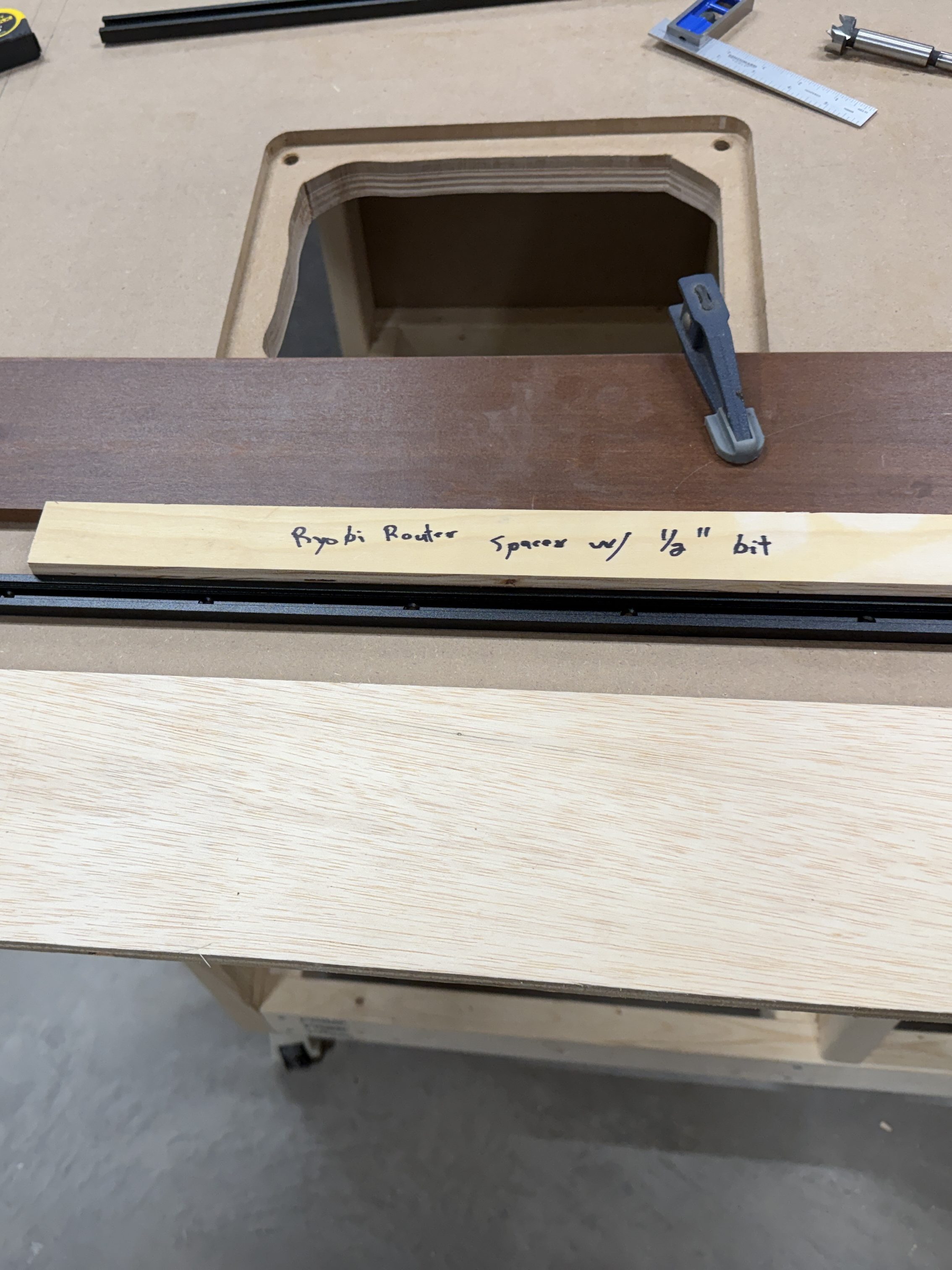
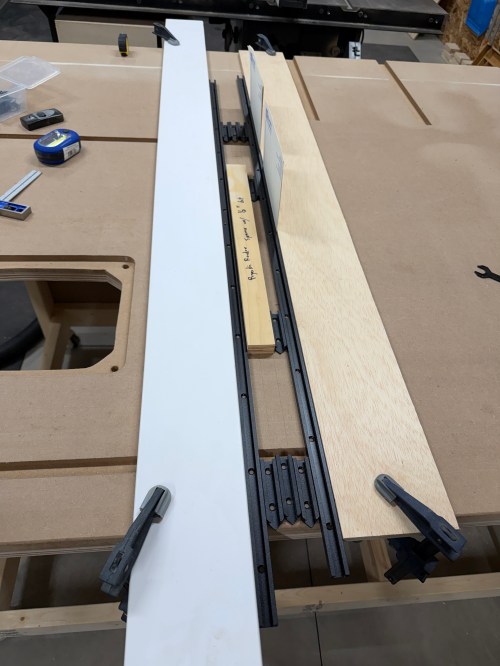
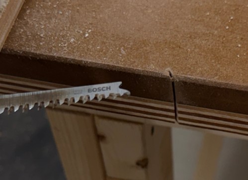
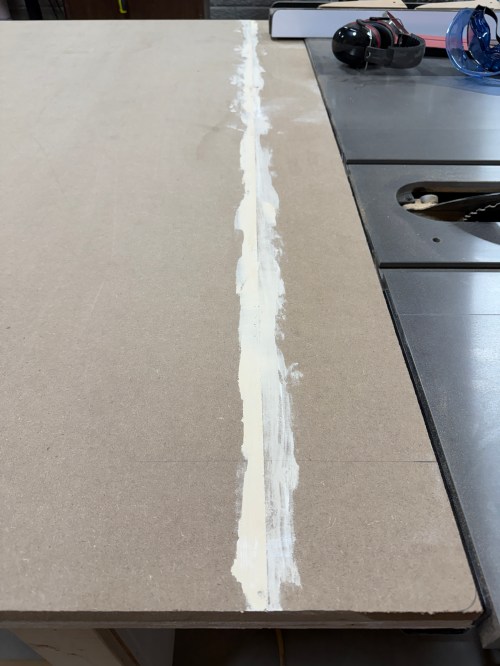
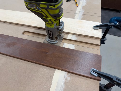
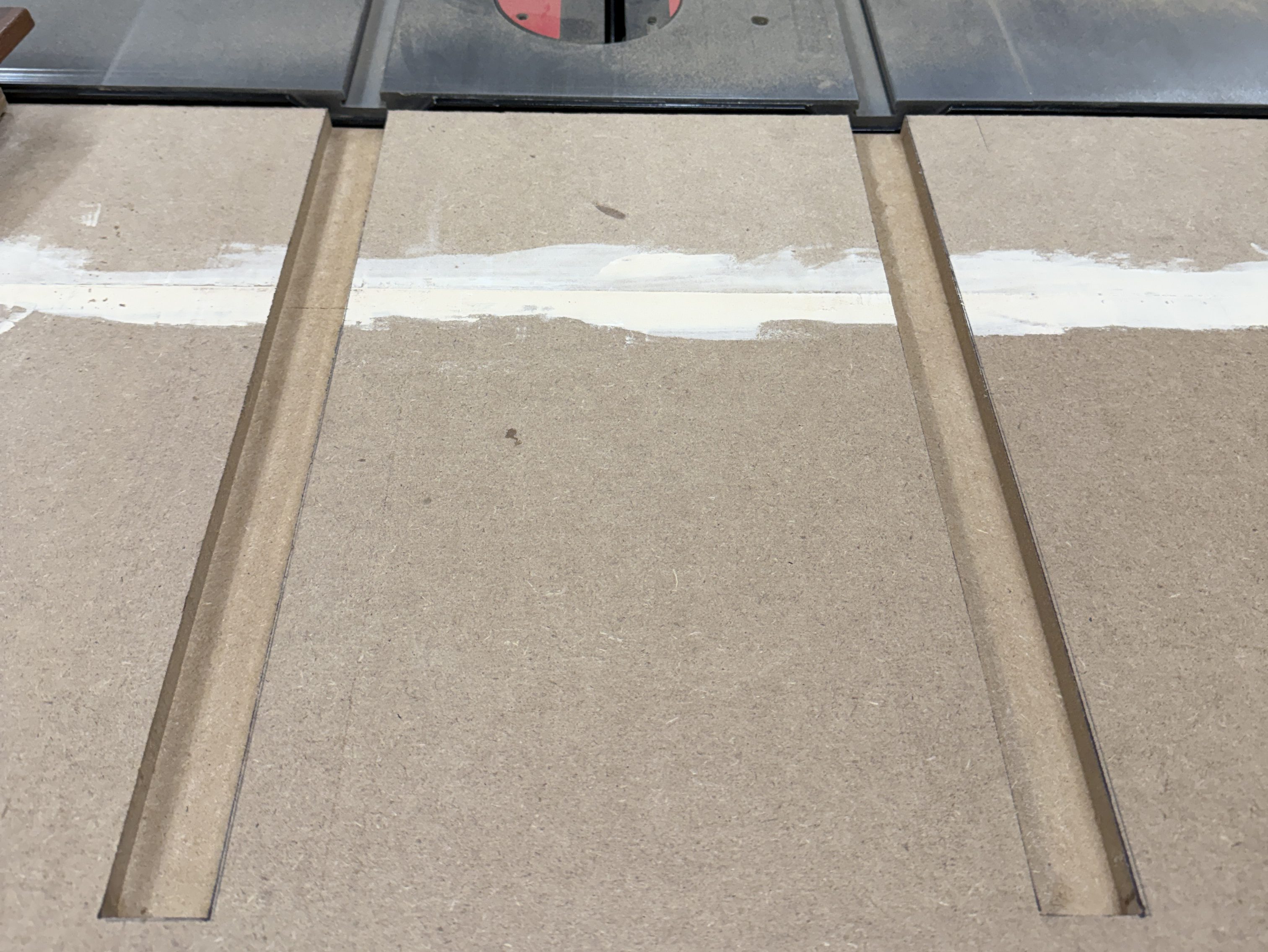
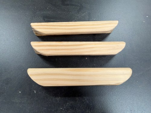
The drawers for the right side of the table was much of the same and went together a lot faster. The table frame is slightly out of square, so the bottom drawer was a touch too tight and the top too loose. I had to route a recess on one and add some spacer material on the other. The handles were cut out of a test piece from the nightstands I made.


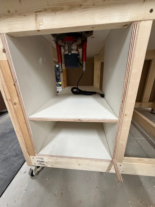
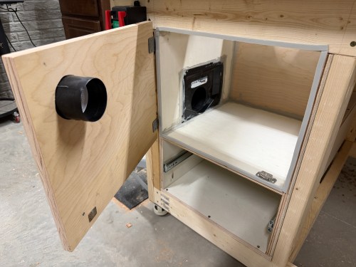
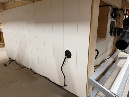
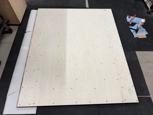
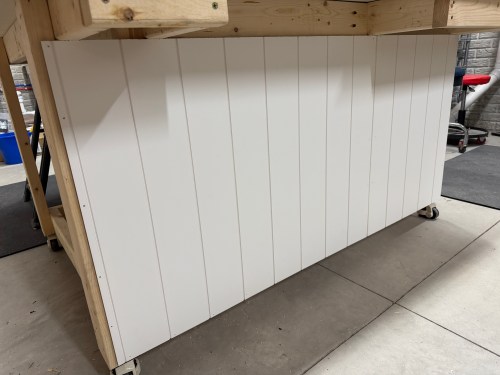
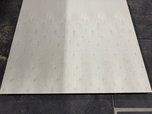
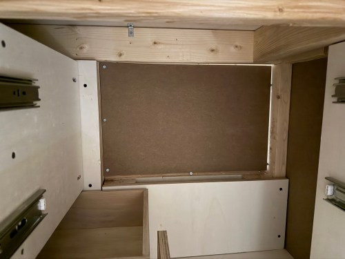
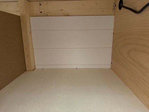
I cut a piece of shiplap paneling and closed off the back of the shelf. This leaves a little unused area in the middle back of the table. If I took out the drawers I could hide something back there. Shhh!
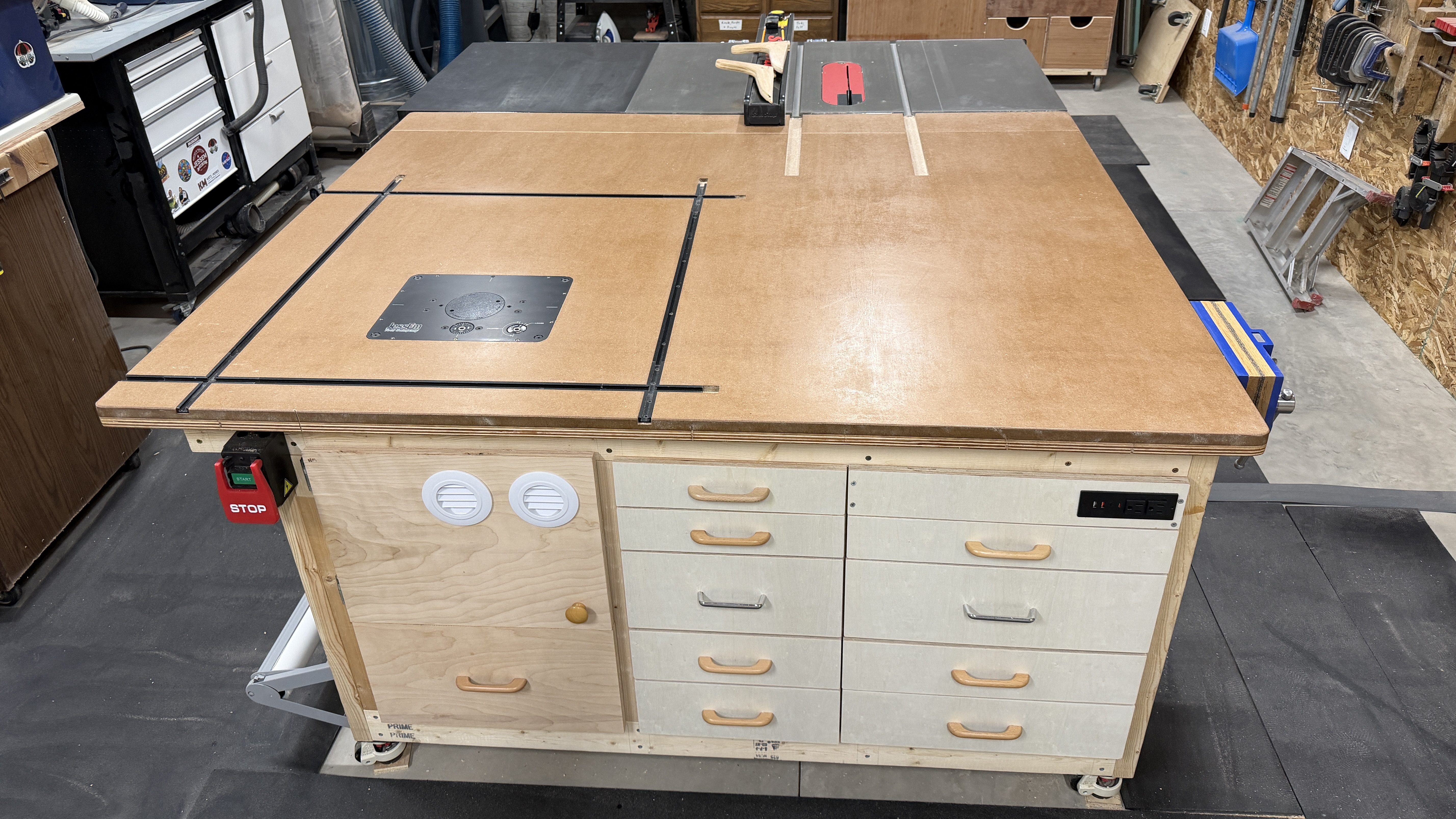
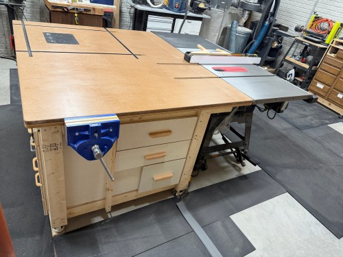
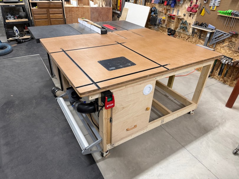
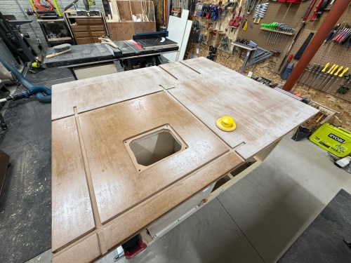
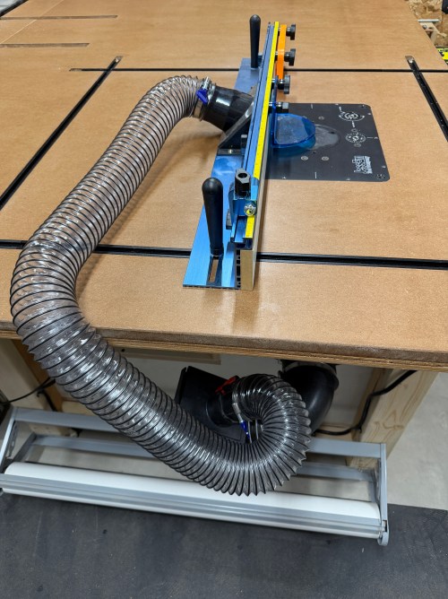
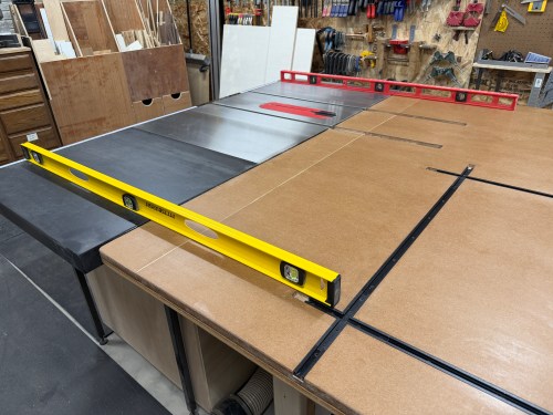
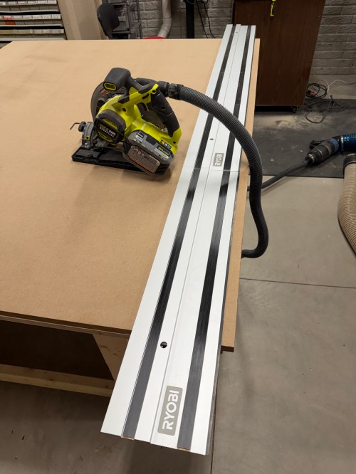
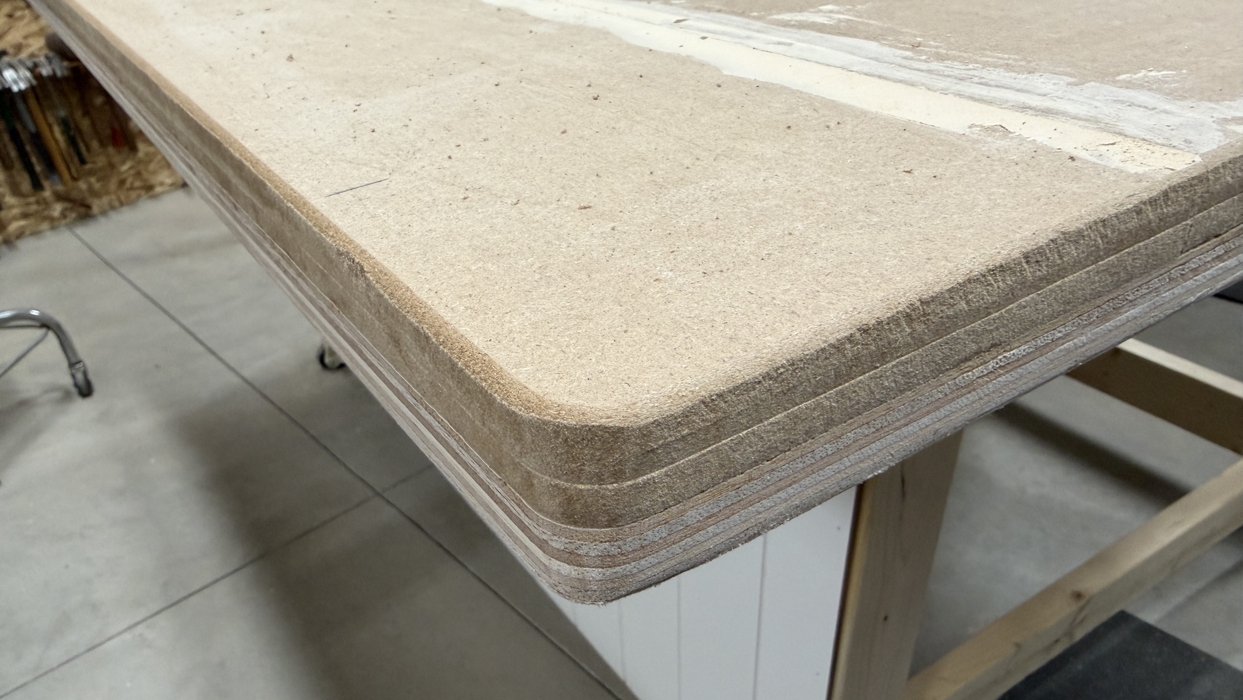
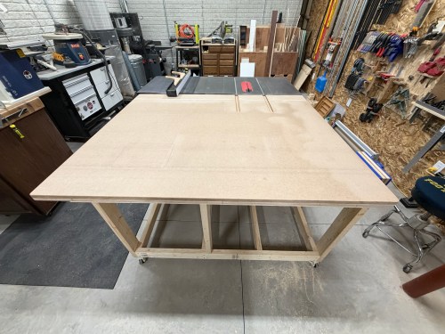
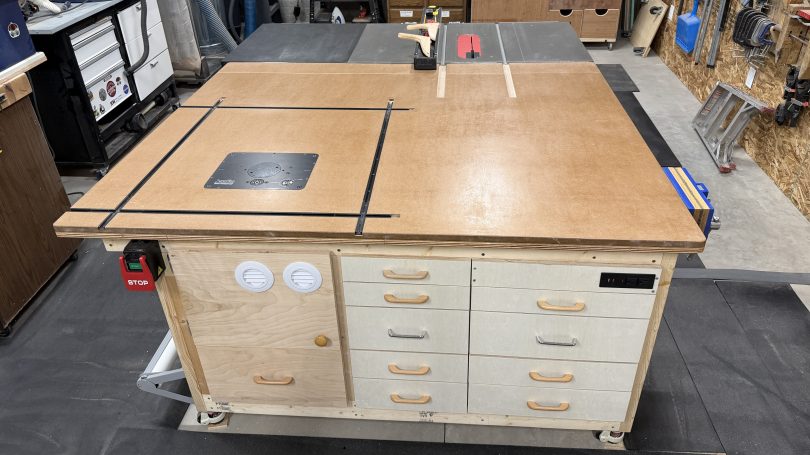
The saw outfeed and the huge work area are already amazing to have. This is really going to improve my processes in the shop. Here are some final photos.