Working from excellent information in a Home Assistant forum thread, I put together an ESPHome device to read information from and send commands to our AlorAir Sentinel HD55S Dehumidifier.

The dehumidifier has an RJ45 port on the front, which can be used to communicate over the CAN bus protocol.
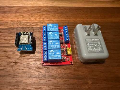
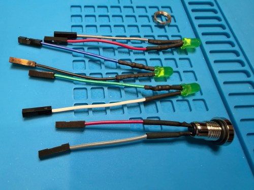
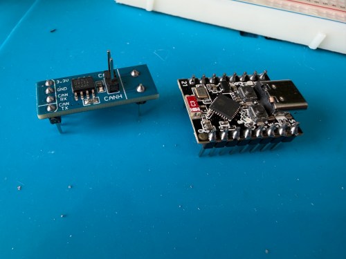
To make my ESPHome device I used:
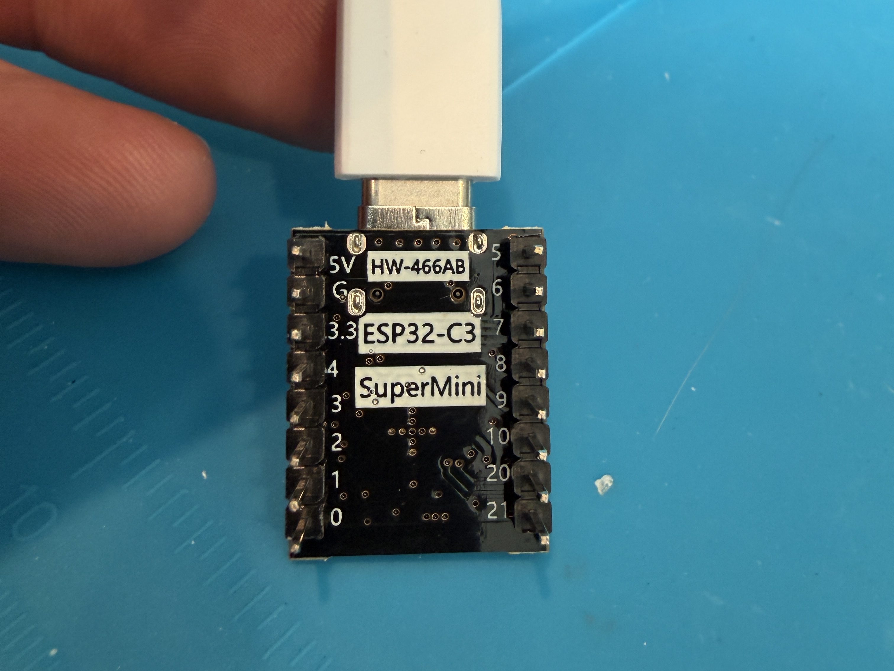
- ESP32 C3 Super Mini Dev Board
- Waveshare SN65HVD230 CAN Board
- RJ45 Breakout
- 100μF Electrolytic Capacitor
- Solderless Breadboard
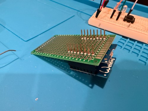
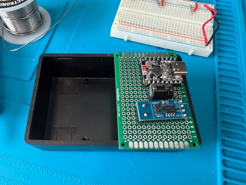
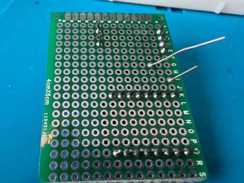
- PCB Board
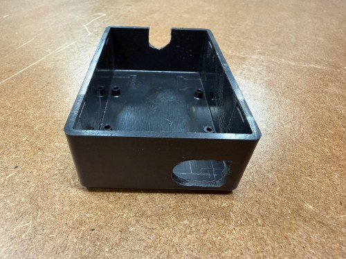
- Project Box
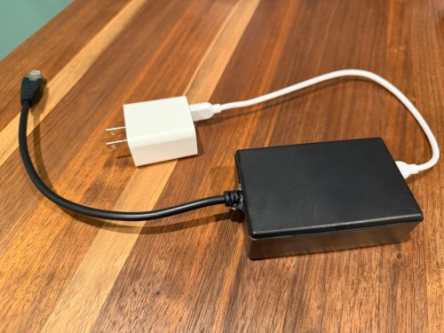
- USB C Charger Block
- USB C Cable
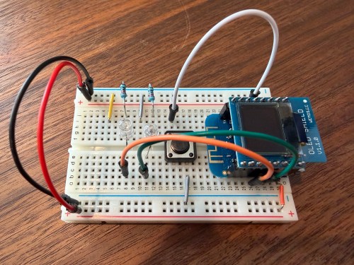
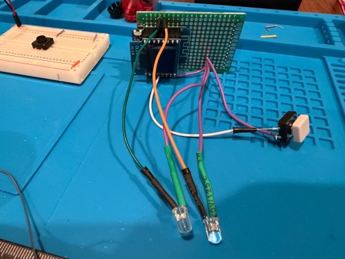
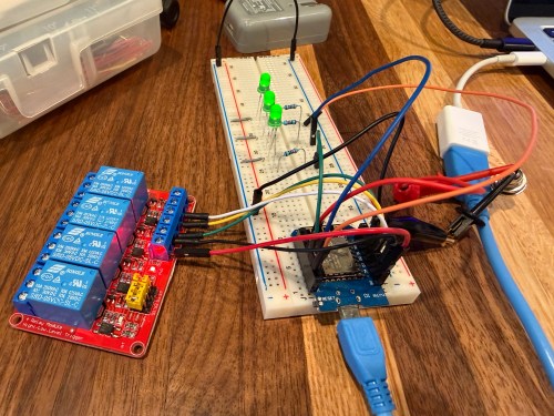
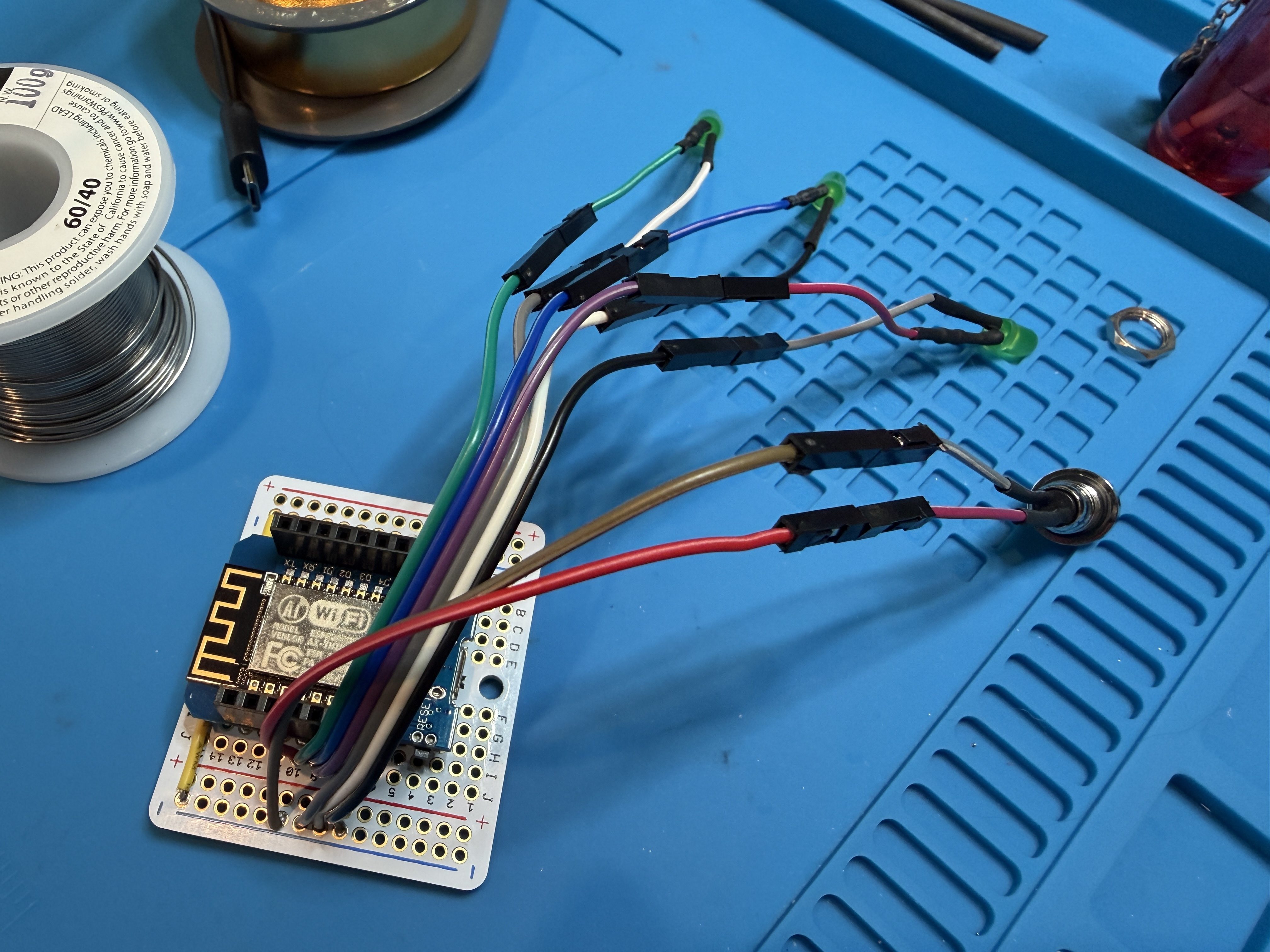
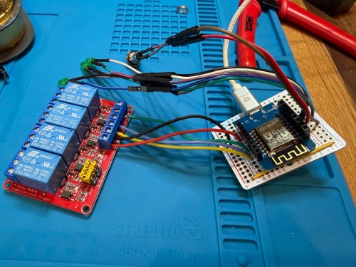
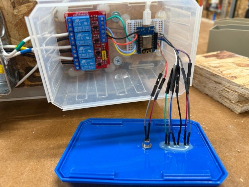
All testing was done on a breadboard.
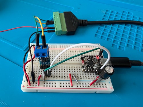
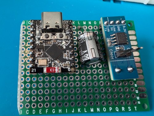
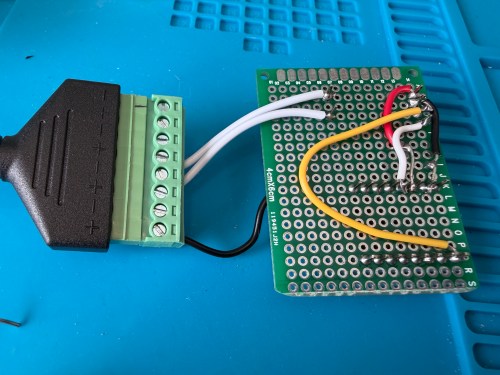
Connections:
- ESP32 G -> CAN Board G -> RJ45 Pin 8 -> Capacitor stripe side
- ESP32 3.3 -> CAN Board 3.3 -> Capacitor non-stripe side
- ESP32 Pin 4 -> CAN Board TX
- ESP32 Pin 5 -> CAN Board RX
- CAN Board CANH -> RJ45 Pin 5
- CAN Board CANL -> RJ45 Pin 4
Start with this YAML for your ESPHome device:
# Add your standard esphome, ota, api, and wifi sections here at the top

logger:
  level: DEBUG

esp32:
  board: esp32-c3-devkitm-1
  framework:
    type: esp-idf

canbus:
  - platform: esp32_can
    id: can
    tx_pin: GPIO4
    rx_pin: GPIO5
    bit_rate: 125KBPS
    can_id: 0x05
    use_extended_id: false

    on_frame:
      - can_id: 0x000
        can_id_mask: 0x000 # This catches EVERYTHING
        then:
          - lambda: |-
              std::string res = "";
              for (int i = 0; i < x.size(); i++) {
                char buf[5];
                sprintf(buf, "%02X ", x[i]);
                res += buf;
              }
              ESP_LOGD("ALORAIR_FINDER", "Received ID: 0x%03X, Data: %s", can_id, res.c_str());

# ====== Periodic Polling to Request Status ======
interval:
  - interval: 10s
    then:
      - canbus.send:
          can_id: 0x123
          use_extended_id: false
          data: [0x00, 0x00, 0x00, 0x00, 0x00, 0x00, 0x00, 0x00]
This will test sending and receiving. After you flash the device and have it connected to the dehumidifier, open the ESPHome device log and look for lines like below.

If you see errors after the send or don’t receive messages back, try changing the bit_rate from 125 to 50, install, and recheck the logs.

If you do receive messages back, make note of the value after Received ID, which is 0x123 above. Then open up the ESPHome device’s YAML again and replace everything below type: esp-idf with the following.
# ──────────────────────────────────────────────
# CAN Bus Protocol
# ──────────────────────────────────────────────
# Bus: 125Kbps, CAN ID 0x123 for both directions
#
# Status frame (from unit):
#   Byte 0: Humidity (%)
#   Byte 1: Setpoint (%), 35 = Continuous mode
#   Byte 2: Temperature (°C)
#   Byte 3: Unused
#   Byte 4: Status bits
#     Bit 0 (0x01): Power on
#     Bit 1 (0x02): Compressor running
#     Bit 3 (0x08): Continuous mode / Defrost
#   Bytes 5-7: Unused?
#
# Command frame (to unit):
#   Byte 0: Setpoint + 128 (to change setpoint)
#   Byte 2: 0x01 = toggle power
#   Continuous mode: send setpoint 35 + 128 = 163 (0xA3)
#
# Echo filtering: commands have byte 0 > 128,
#   status frames have byte 0 < 100
# ──────────────────────────────────────────────

script:
  - id: refresh_status
    mode: restart
    then:
      - delay: 1s
      - canbus.send:
          can_id: 0x123
          data: [0x00, 0x00, 0x00, 0x00, 0x00, 0x00, 0x00, 0x00]

interval:
  - interval: 60s
    then:
      - script.execute: refresh_status

time:
  - platform: homeassistant
    id: homeassistant_time

globals:
  - id: power
    type: bool
    restore_value: yes
  - id: continuous
    type: bool
    restore_value: yes

canbus:
  - platform: esp32_can
    id: can
    tx_pin: GPIO4
    rx_pin: GPIO5
    bit_rate: 125KBPS
    can_id: 0x05
    use_extended_id: false

    on_frame:
      - can_id: 0x123
        then:
          - lambda: |-
              if (x.size() < 5 || x[0] == 0) return;

              // Debug logging (uncomment the lines below if you need to debug the data packets)
              // char buf[64];
              // snprintf(buf, sizeof(buf), "%02X %02X %02X %02X %02X %02X %02X %02X",
              //   x[0], x.size() > 1 ? x[1] : 0,
              //   x.size() > 2 ? x[2] : 0, x.size() > 3 ? x[3] : 0,
              //   x.size() > 4 ? x[4] : 0, x.size() > 5 ? x[5] : 0,
              //   x.size() > 6 ? x[6] : 0, x.size() > 7 ? x[7] : 0);
              // ESP_LOGD("canbus", "0x123 [%d]: %s", x.size(), buf);

              // Filter out command echoes (byte 0 > 128)
              if (x[0] >= 100) return;

              // Byte 0: Humidity (%)
              id(humidity).publish_state(x[0]);

              // Byte 1: Setpoint (%), 35 = continuous mode
              id(setpoint_value).publish_state(x[1]);

              // Byte 2: Temperature (°C, convert to °F)
              id(temperature).publish_state(x[2] * 9.0 / 5.0 + 32.0);

              // Byte 4: Status bits
              bool power_on    = x[4] & 0x01;
              bool compressor  = x[4] & 0x02;
              bool cont_defrost = x[4] & 0x08;
              bool is_continuous = (x[1] == 35);

              // Update sensors
              id(compressor_status).publish_state(compressor);
              id(defrost_status).publish_state(cont_defrost && !is_continuous);

              // Sync globals
              id(power) = power_on || is_continuous;
              id(continuous) = is_continuous;

              // Build status string
              std::string status_str;
              if (!power_on && !is_continuous) {
                status_str = "Off";
              } else if (is_continuous && cont_defrost) {
                status_str = "Continuous";
                if (compressor) status_str += ", Compressor On";
              } else if (cont_defrost) {
                status_str = "Defrosting";
              } else if (compressor) {
                status_str = "Running";
              } else if (power_on) {
                status_str = "Idle";
              }
              id(status_text).publish_state(status_str.c_str());

              // Update timestamp
              auto time = id(homeassistant_time).now();
              if (time.is_valid()) {
                char time_str[20];
                time_t now = time.timestamp;
                strftime(time_str, sizeof(time_str), "%H:%M:%S", localtime(&now));
                id(last_update).publish_state(time_str);
              }

              // Alert on unexpected bits in byte 4
              uint8_t unknown_b4 = x[4] & ~0x0B; // mask out known bits 0,1,3
              if (unknown_b4 != 0) {
                ESP_LOGW("canbus", "Unknown bits in byte 4: 0x%02X", unknown_b4);
                id(unknown_data).publish_state("Byte 4 unknown bits: 0x" +
                  std::string(1, "0123456789ABCDEF"[(unknown_b4 >> 4) & 0x0F]) +
                  std::string(1, "0123456789ABCDEF"[unknown_b4 & 0x0F]));
              }

              // Alert on any non-zero data in bytes 3, 5, 6, 7
              if (x[3] != 0 || x[5] != 0 || x[6] != 0 || x[7] != 0) {
                ESP_LOGW("canbus", "Unexpected data in unused bytes: B3=0x%02X B5=0x%02X B6=0x%02X B7=0x%02X", x[3], x[5], x[6], x[7]);
                char msg[64];
                snprintf(msg, sizeof(msg), "B3:%02X B5:%02X B6:%02X B7:%02X", x[3], x[5], x[6], x[7]);
                id(unknown_data).publish_state(msg);
              }

text_sensor:
  - platform: template
    name: "Status"
    id: status_text
  - platform: template
    name: "Last CAN Update"
    id: last_update
  - platform: template
    name: "Unknown CAN Data"
    id: unknown_data
    entity_category: diagnostic

sensor:
  - platform: template
    name: "Humidity"
    id: humidity
    unit_of_measurement: "%"
    device_class: humidity
    state_class: measurement
    accuracy_decimals: 0
    filters:
      - median:
          window_size: 5
          send_every: 1
      - delta: 1

  - platform: template
    name: "Temperature"
    id: temperature
    unit_of_measurement: "°F"
    device_class: temperature
    state_class: measurement
    accuracy_decimals: 0
    filters:
      - median:
          window_size: 5
          send_every: 1
      - delta: 1

  - platform: template
    name: "Setpoint"
    id: setpoint_value
    unit_of_measurement: "%"
    accuracy_decimals: 0

binary_sensor:
  - platform: template
    name: "Compressor"
    id: compressor_status
    device_class: power

  - platform: template
    name: "Defrost"
    id: defrost_status
    device_class: cold

number:
  - platform: template
    name: "Change Setpoint"
    id: setpoint_control
    min_value: 36
    max_value: 90
    step: 1
    optimistic: true
    set_action:
      then:
        - lambda: |-
            uint8_t sp = (uint8_t)(x + 128);
            std::vector<uint8_t> data = { sp, 0x00, 0x00, 0x00, 0x00, 0x00, 0x00, 0x00 };
            id(can).send_data(0x123, false, data);
        - script.execute: refresh_status

switch:
  - platform: template
    name: "Power"
    id: enable_dehumid
    lambda: return id(power);
    turn_on_action:
      - lambda: |-
          if (!id(power)) {
            std::vector<uint8_t> data = {0x00, 0x00, 0x01, 0x00, 0x00, 0x00, 0x00, 0x00};
            id(can).send_data(0x123, false, data);
          }
      - script.execute: refresh_status
    turn_off_action:
      - lambda: |-
          if (id(power)) {
            // If in continuous mode, exit continuous first by setting a normal setpoint
            if (id(continuous)) {
              float sp_val = id(setpoint_control).state;
              if (std::isnan(sp_val) || sp_val < 36) sp_val = 55;
              uint8_t sp = (uint8_t)(sp_val + 128);
              std::vector<uint8_t> data = { sp, 0x00, 0x00, 0x00, 0x00, 0x00, 0x00, 0x00 };
              id(can).send_data(0x123, false, data);
              delay(500);
            }
            std::vector<uint8_t> data = {0x00, 0x00, 0x01, 0x00, 0x00, 0x00, 0x00, 0x00};
            id(can).send_data(0x123, false, data);
          }
      - script.execute: refresh_status

  - platform: template
    name: "Continuous Mode"
    id: continuous_mode_enable
    lambda: return id(continuous);
    turn_on_action:
      - lambda: |-
          // Send setpoint 35 (below minimum) to enter continuous mode
          uint8_t sp = (uint8_t)(35 + 128);
          std::vector<uint8_t> data = { sp, 0x00, 0x00, 0x00, 0x00, 0x00, 0x00, 0x00 };
          id(can).send_data(0x123, false, data);
      - script.execute: refresh_status
    turn_off_action:
      - lambda: |-
          // Exit continuous by sending a normal setpoint
          float sp_val = id(setpoint_control).state;
          if (std::isnan(sp_val) || sp_val < 36) {
            sp_val = id(setpoint_value).state;
          }
          if (std::isnan(sp_val) || sp_val < 36) {
            sp_val = 55;
          }
          uint8_t sp = (uint8_t)(sp_val + 128);
          std::vector<uint8_t> data = { sp, 0x00, 0x00, 0x00, 0x00, 0x00, 0x00, 0x00 };
          id(can).send_data(0x123, false, data);
      - script.execute: refresh_status

automation:
  - alias: "Alorair Unknown CAN Data Alert"
    trigger:
      - platform: state
        entity_id: sensor.alorair_dehumidifier_unknown_can_data
        not_to:
          - ""
          - "unknown"
          - "unavailable"
    action:
      - service: notify.mobile_app_YOUR_PHONE
        data:
          title: "Alorair: Unknown CAN Data"
          message: "{{ trigger.to_state.state }}"
          data:
            tag: alorair_unknown_can
            importance: low
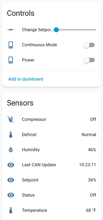
If your ID was different than 0x123 (0x3b0 seems common), change the can_id under on_frame. Update mobile_app_YOUR_PHONE for your phone. Install this new code to the device. Go to Settings -> Devices & services -> ESPHome. If your device isn’t already listed, add it, and click through to see the entities. Hopefully you see the Controls and Sensors with data.
Try to toggle the power and change the setpoint. If it’s working, the dehumidifier should respond. Good luck! If all is working, I suggest adjusting your logging level to WARN. There is some stuff in the YAML to alert if the unit sends data that isn’t recognized, because there might be flags or statuses not implemented.
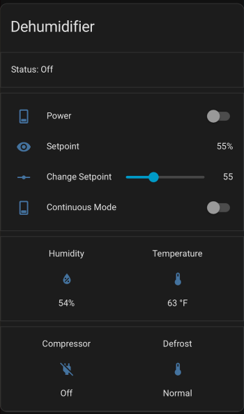
If you install the stack-in-card via HACS, here’s some YAML for your dashboard. Make sure to update the entity names to match what you have.
type: custom:stack-in-card
title: Dehumidifier
cards:
  - type: markdown
    content: >
      Status: {{ states('sensor.alorair_dehumidifier_status') }}

  - type: entities
    entities:
      - entity: switch.alorair_dehumidifier_power
        name: Power
      - entity: sensor.alorair_dehumidifier_setpoint
        name: Setpoint
      - entity: number.alorair_dehumidifier_change_setpoint
        name: Change Setpoint
      - entity: switch.alorair_dehumidifier_continuous_mode
        name: Continuous Mode
  - type: glance
    entities:
      - entity: sensor.alorair_dehumidifier_humidity
        name: Humidity
      - entity: sensor.alorair_dehumidifier_temperature
        name: Temperature
    columns: 2

  - type: glance
    entities:
      - entity: binary_sensor.alorair_dehumidifier_compressor
        name: Compressor
      - entity: binary_sensor.alorair_dehumidifier_defrost
        name: Defrost
    columns: 2
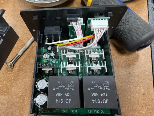
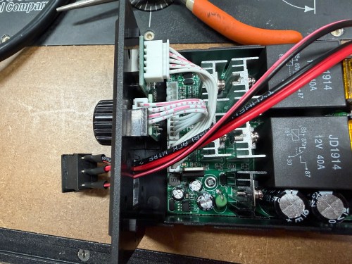
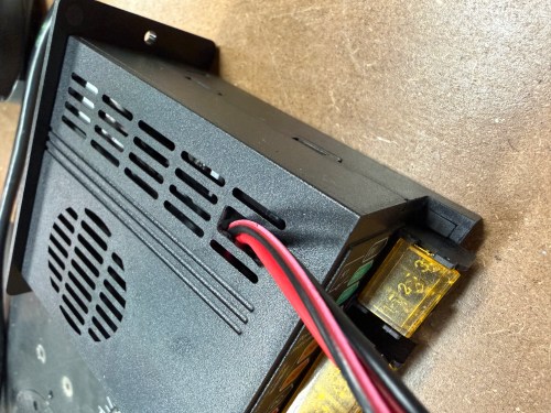
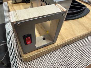
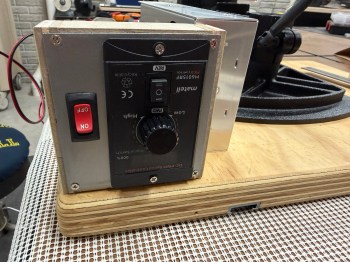
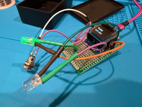
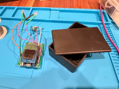
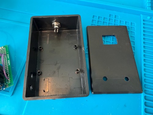
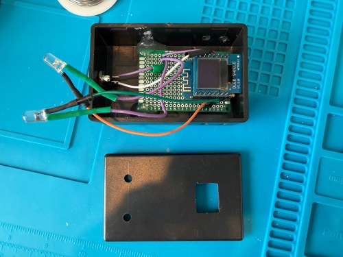
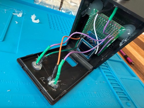
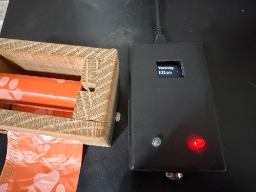
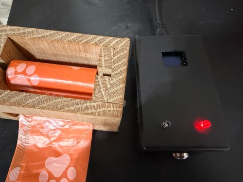
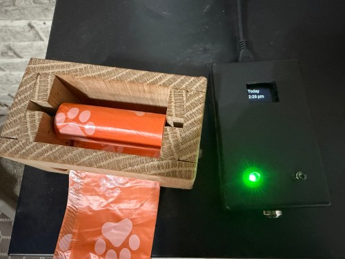
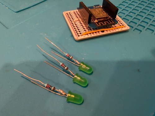
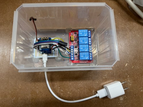
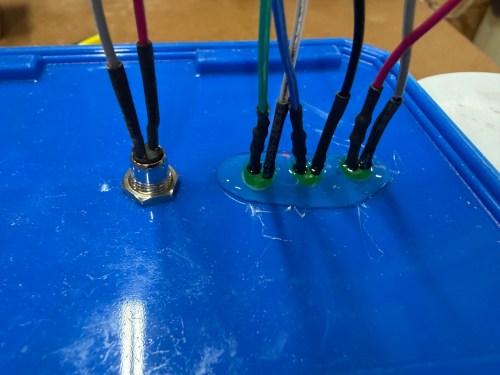
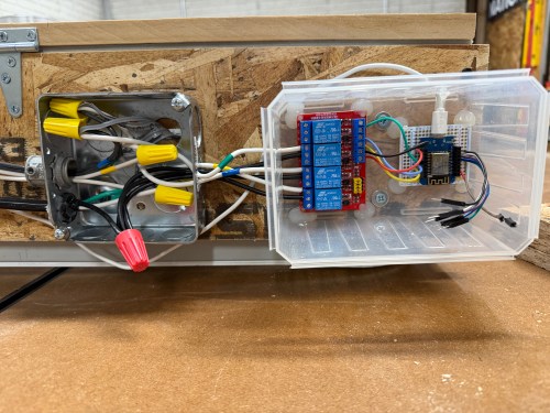
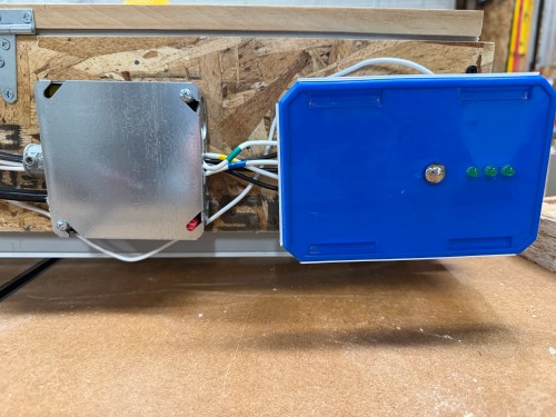
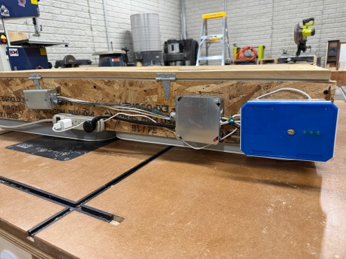
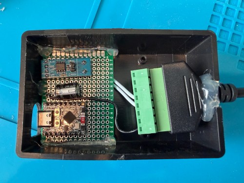
Once I got everything working, I soldered to a permanent board and hot glued it inside a project box.
I haven’t worked on automations yet, but I have time before spring arrives when I need to run the dehumidifier.