I finally organized all of my air gun bullets, even using my original idea of boxes on French cleats. I got these plastic containers for super cheap so I didn’t even have to make my own out of wood. First time using the Dymo label maker I bought, which really helps out too.
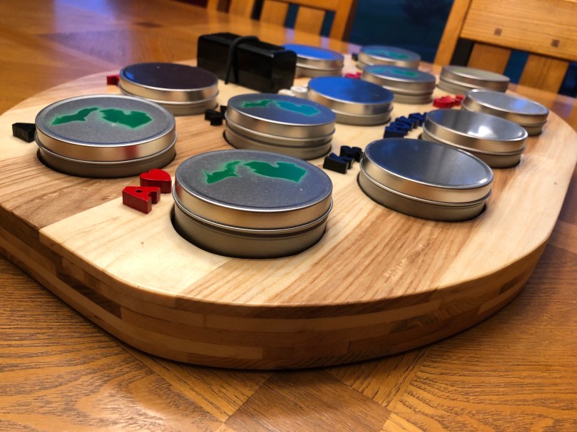
Our family always had fun playing our own version of Michigan Rummy (there is also a version called Tripoly) as kids. Then last year we played it almost every night on our family vacation, using a modified board. It gave me an idea to build a custom board for my Mom.
As soon as I saw this case with two decks of cards at an estate sale several months ago I knew it would be neat for the board. I think I paid $1. The copyright date is 1947!
I’ve been wanting to build something with pallet wood and thought it would give the board a neat look. You can get free pallets all over by looking on Facebook Marketplace or Craigslist.
With the help of my pallet buster and some brute force, I broke down the pallets.
These containers with covers are from Menard’s, free after rebate. Another perfect piece for the project. I laid everything out to get a feel for the size.
After taking measurements, I mocked up a 3D model of the board’s top layer in SketchUp (download on GitHub). It would be about 24×16 inches.
I also printed out the text using Arial Black for the letters/numbers and Futura for the suit symbols.
I trimmed, planed, and jointed a bunch of boards.
Then glued up panels that would make the top and bottom of the board.
I measured and marked a bunch of lines and then placed everything where it would end up to get a better feel for the size and layout. I liked it.
I finished drawing in more details and did a rough cut of the outer shape with my band saw.
The scroll saw got heavy use cutting everything out. I also cleaned up the holes and edges with various sandering. You can see a couple of places where I started to carve in the text. It didn’t take long to scrap that plan though; it was going to take forever and some of the wood was really soft so I wasn’t happy with how it would turn out.
I decided to use raised letters that I’d glue on. After doing a bunch of work, I realized this would be much better because the containers would be up above the board, so it would have been hard to see the recessed lettering.
I used the band saw to cut all of the letters. More sanding to clean them up and then some spray paint.
I didn’t get any pictures of the next steps, which probably took the longest. I used a bunch of the cutoffs to build up an outer support ring as well as eight stacks in the middle to prevent something heavy from breaking the top or bottom panel. There was a lot of gluing, clamping, and band saw trimming. Finally I had enough layers and I was able to glue on the bottom panel.
After the glue dried I did a lot of sanding on every surface. I had tied in a piece of bungie cord earlier that would hold the card case in place. Then I drilled shallow holes so I could glue in (with epoxy) rare Earth magnets to hold the containers in place. I used CA glue to attach all of the lettering.
It was finally time for some finish. I used three coats of shellac (with light sanding after each coat) and a coat of wax polish. I spray painted the Michigan map on half of the containers and gave them two clear coats. The last thing was to stick some of those felt pad circles to the bottom and it was done. I really like how this turned out.
The layering you can see from the sides is a neat look.
Last night was the first time I’ve done a lot of work with the scroll saw. I used the foot switch I’d made earlier this year and I can’t imagine using this saw without one. If you do any scroll sawing, get yourself one. The wood on the table of the saw is a piece of thin scrap plywood stuck down with tape to act as a zero clearance insert.
While cleaning up the feed rollers on my Dad’s Craftsman 351.233831 Planer I noticed there were really beat up.
Old infeed roller
Unfortunately the part (#8520) is discontinued and I couldn’t find an aftermarket one anywhere online. I stumbled across some forum posts discussing roller resurfacing, so I got some quotes.
Mid American Rubber, which is actually here in Michigan, wanted $137 for each roller!
These first two had big forms on their website with diagrams showing how to get all of the measurements they requested.
I had to call Feedrollers.com and provide some info. A day later they got back to me with a price of $57 each.
Western Roller Corporation had an online form but it was very basic so I only provided the model of the planer and the part number. I got an email saying, “most of these small table-top type planers we recover your existing shafts for $65.00 to $100.00 each.” That’s a pretty wide range, so I sent over the measurements provided to the other companies and they quoted $68.88 each.
I went with the cheapest one since these aren’t for a production shop of any kind. I shipped out the rollers and got them back exactly 3 weeks later.
I’m really impressed with these. Hopefully they hold up well for my Dad. After installing the rollers I swapped out and aligned all of the cutter knives. With this and all of the previous work, the planer runs like a brand new machine.
I wanted to use pallet wood for a project and my brother has been using a lot of it, so I asked for his breakdown method. He said I should make a pallet buster. So I did.
This is the entry feed roller I took out of Dad’s Craftsman 351.233831 Planer. Looks like the wood pieces took the name “feed roller” quite literal and were chewing on it! Pretty sure this wasn’t safe, so glad to be replacing it before giving the machine back to him.
I bought a small set of digital calipers so instead of cutting a 3rd slot in the old block (each set slid in from the front) I made a new one with holes so each set goes in from the top and can’t fall out.
Back in early November I found this Delta TP305 planer for $100 on craigslist.
It was obvious the owner took care of his tools, he had just replaced the blades, and also had a set of new blades, so the price was a steal. It didn’t have any type of dust/chip collection though.
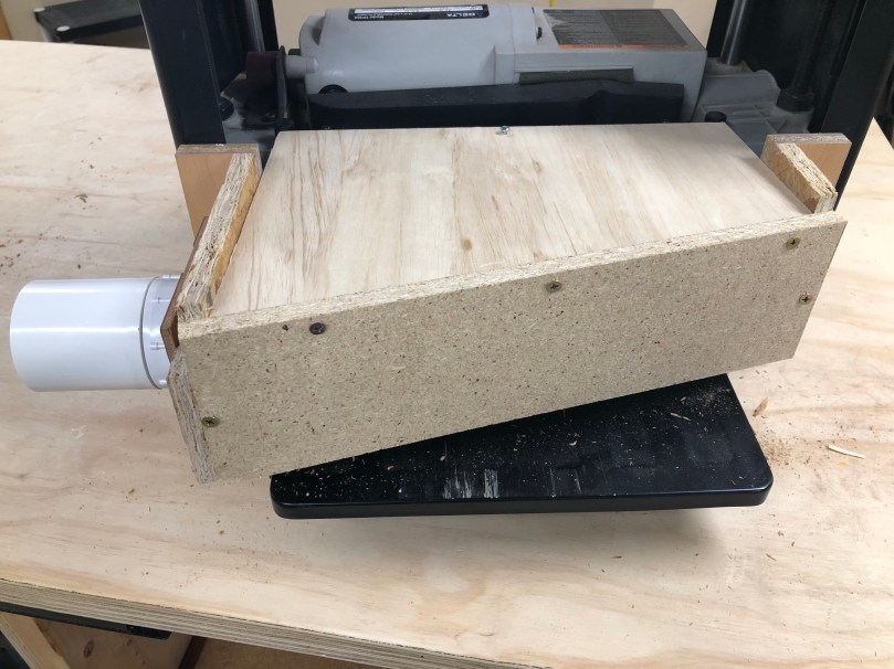
When Delta produced this planer, the dust collection attachment was an extra accessory. I decided to make my own because I don’t understand this design. Why would you want your hose hanging over the outfeed? Too much risk of the work piece getting jammed on the way out, which is extremely dangerous.
I found a neat idea on YouTube and went with a similar plan. Here is what the outfeed looks like normally.
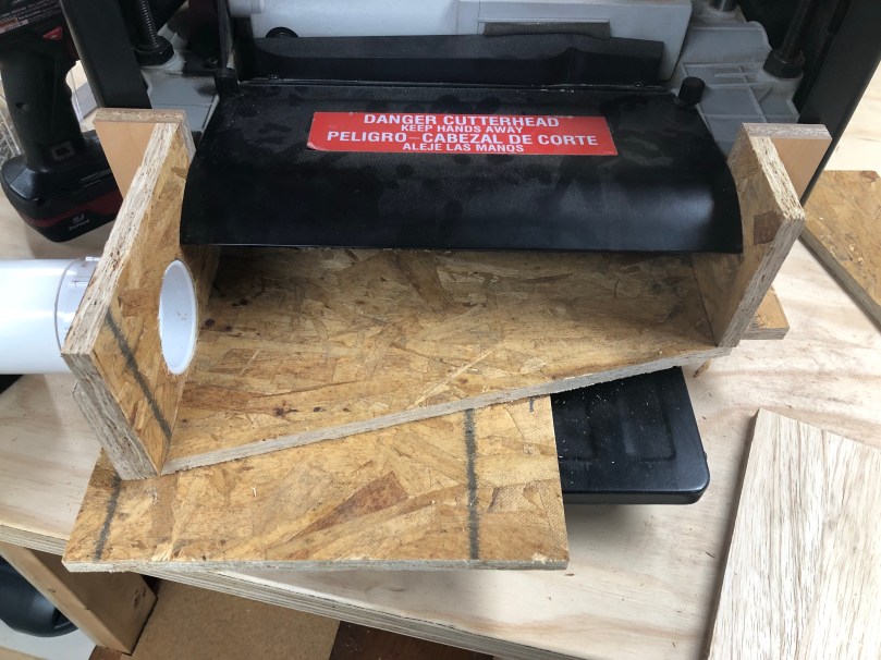
I first cut some pieces to make the sides and bottom of a box.
I screwed the right side together. Then I held it up against the planer to get the exact positioning before screwing in the left side. I wanted a snug fit.
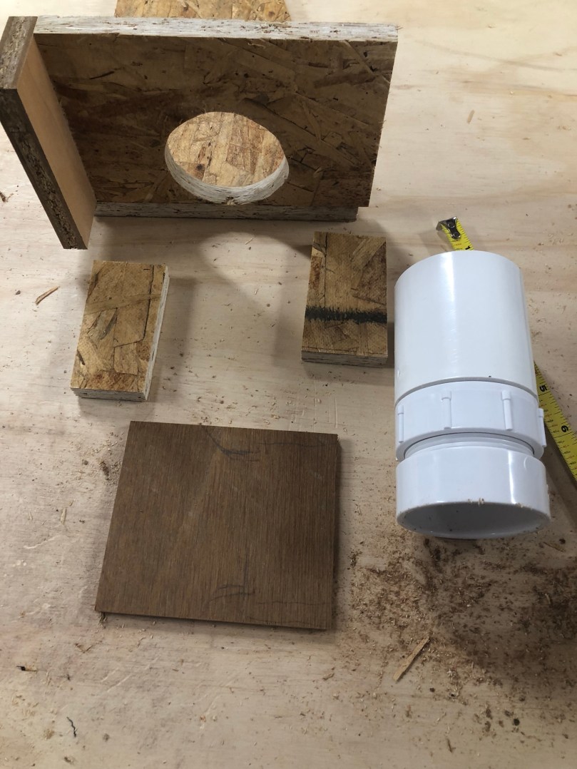
I cut and sanded a hole in the side for some PVC parts.
Grabbed a few scraps that would be used to hold the PVC in place.
Cut a hole in the thin piece, boxed in the male PVC part, and screw it all together.
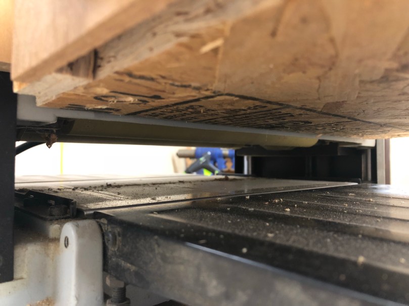
Then I put a spacer under my in-progress box and adjusted the planer’s height. It was important to use a spacer for these next steps because I don’t want the bottom of the box to have any chance of jamming up the wood coming out of the planer. I gave it about 1/8″ of breathing room.
I cut a piece for the top. Then while putting pressure on the edge that makes contact with the planer dust chute I screwed this piece to the sides. At this point I was able to remove the spacer because the tight fit was able to hold the box in place.
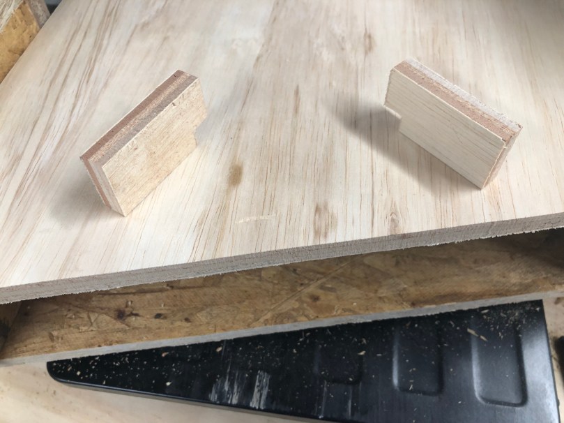
I wanted to prevent the box from sagging or shifting down during use though. So I cut two little pieces.
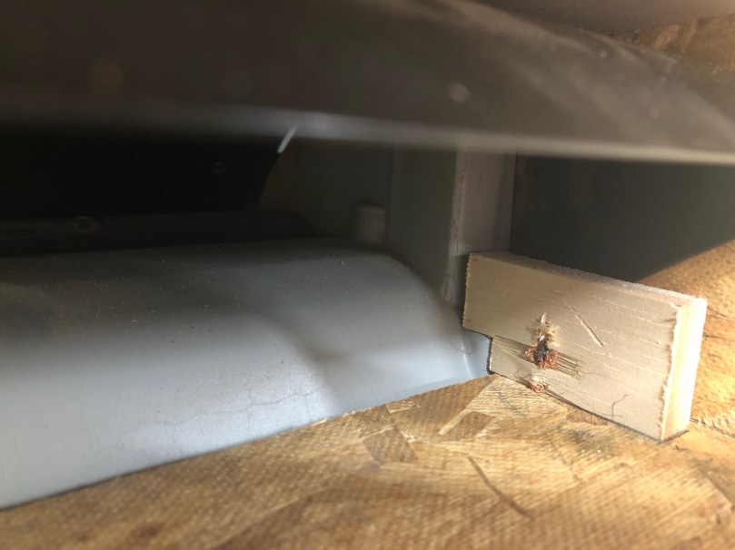
Screwed them in from the bottom on each side. Notice how the kind of grab on to some ledges of the planer. This is a simple way to prevent the bottom of the box from going any lower.
I drilled a hole in the top and through the metal chute. Combined with the tight fit and those blocks, now this thing can only shift up and away from the outfeed path.
The final step was to square up the back edges, cut a piece, and screw it in. There are no screws on the bottom of the back face because I used a scrap piece that wasn’t tall enough to have room for screws there. I did use some glue though.
Here you can see the clearance between the box and the outfeed I mentioned earlier.
Due to the materials I skipped using any wood glue except when I put the back face on. I did go back and hot glue all of the joints so it would be sealed for a better vacuum.
This was an easy build. The only modification to the planer was the screw hole and the whole unit can be removed by taking out that screw.
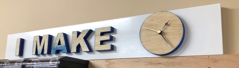
I was always wondering what time it was when working in my shop. So I took apart an old clock I had in a closet. Used the hands, gears, and battery compartment to make this.
I didn’t occur to me it reads as a full sentence, “I make time” until after it was done.


 When Delta produced this planer, the dust collection attachment was an extra accessory. I decided to make my own because I don’t understand this design. Why would you want your hose hanging over the outfeed? Too much risk of the work piece getting jammed on the way out, which is extremely dangerous.