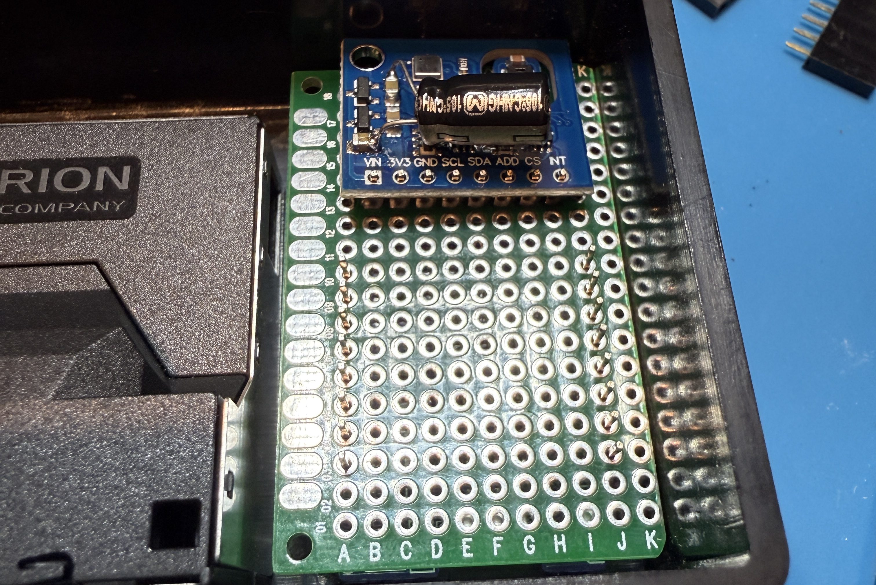
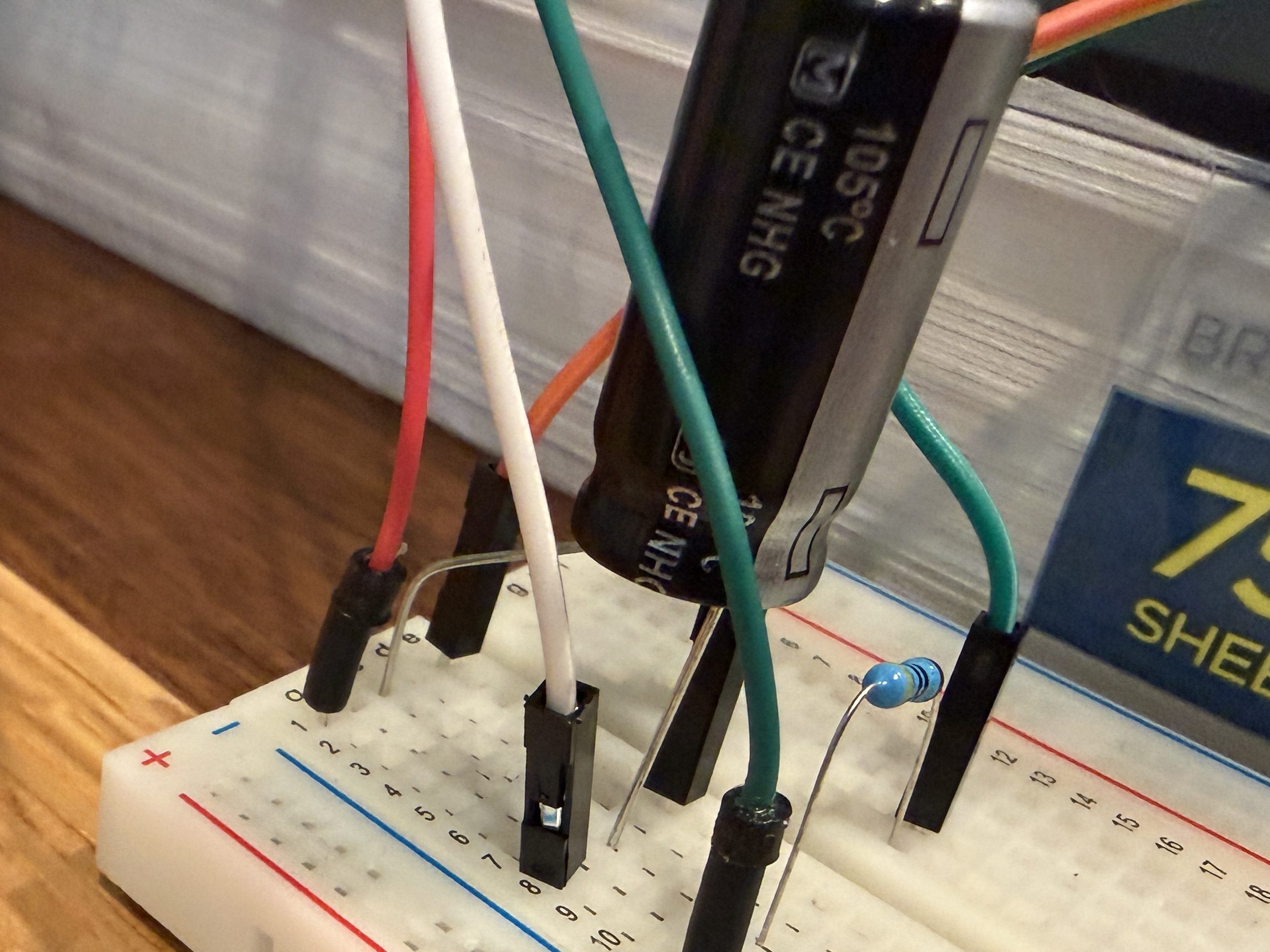
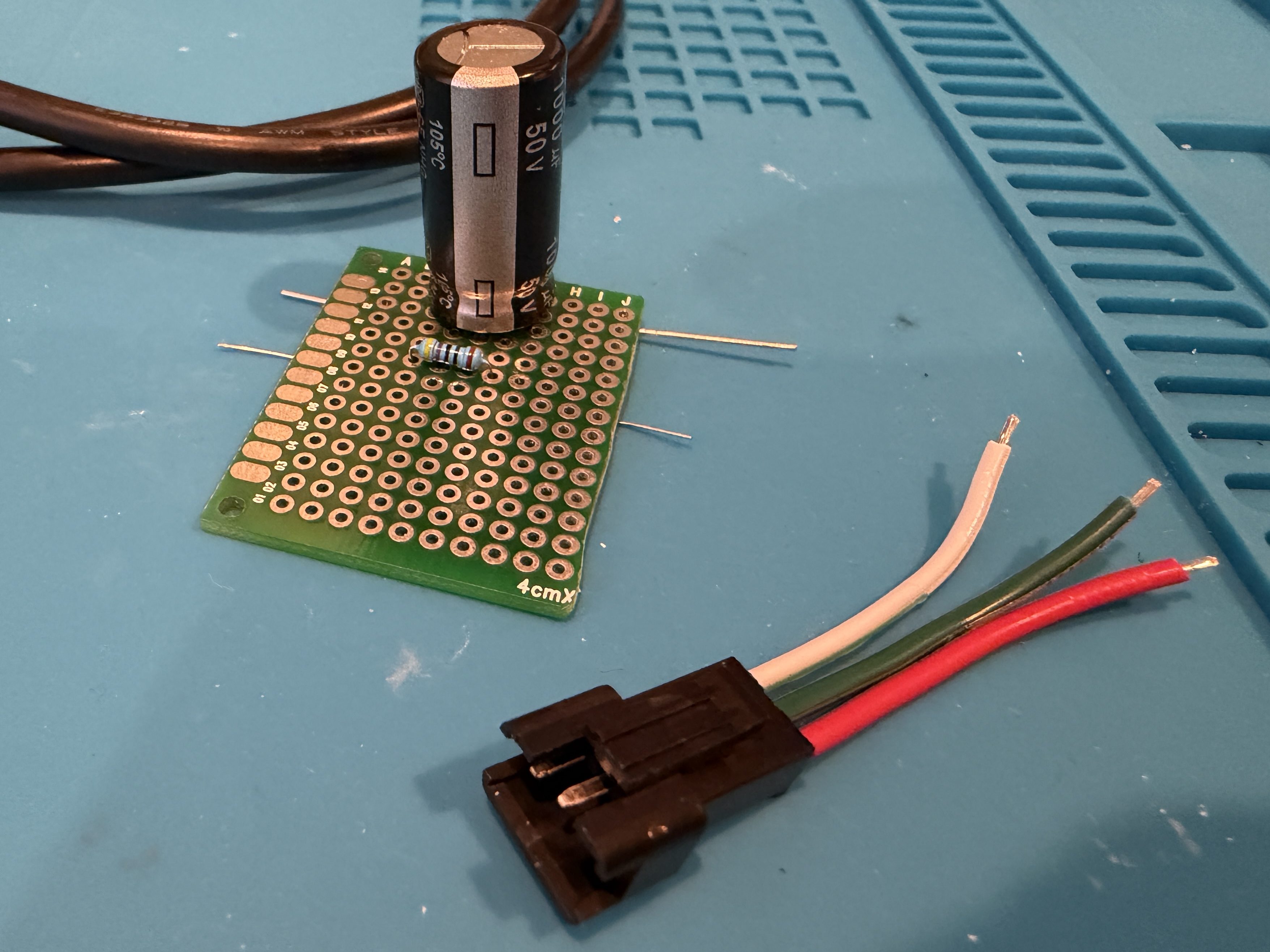
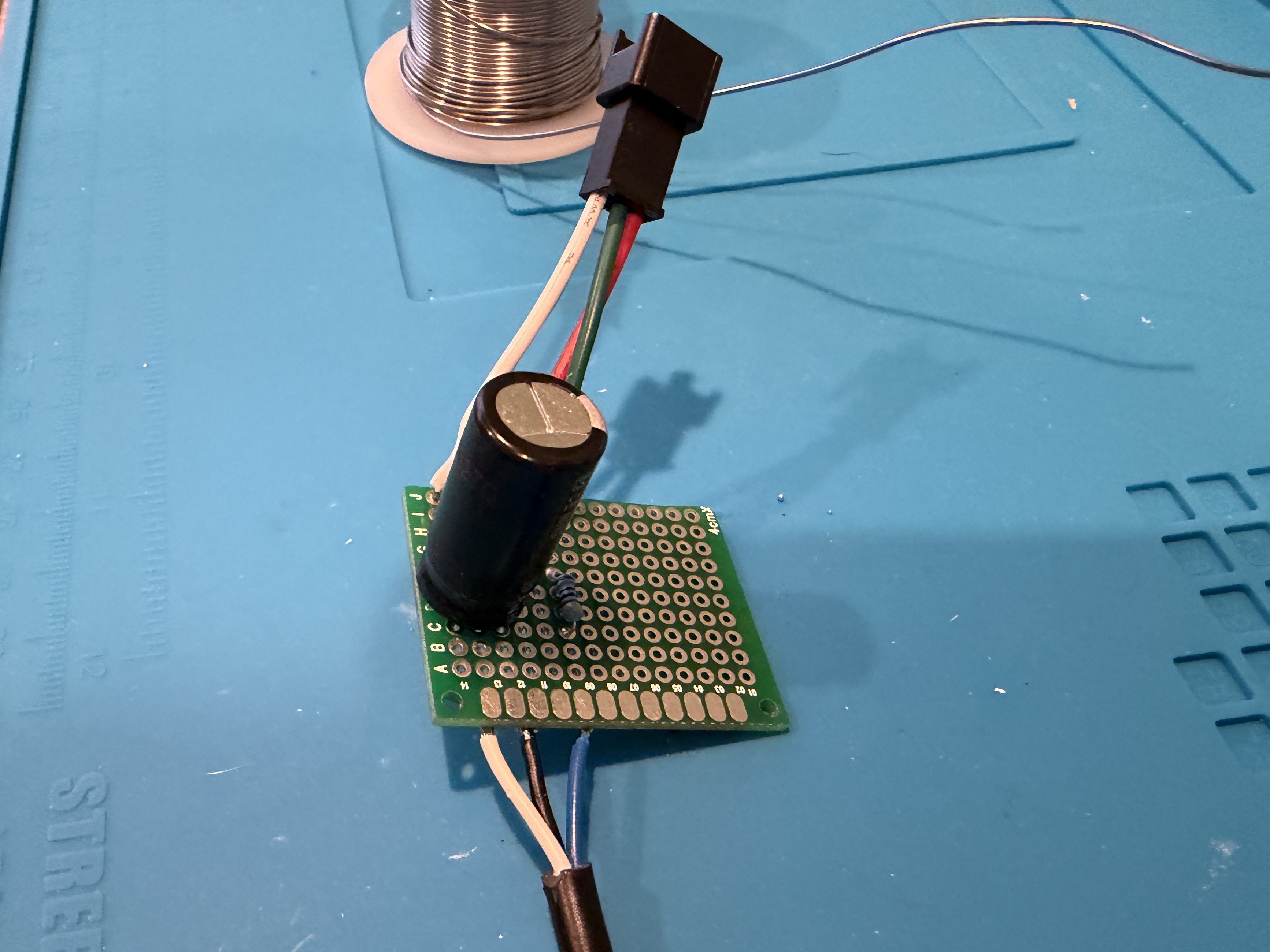
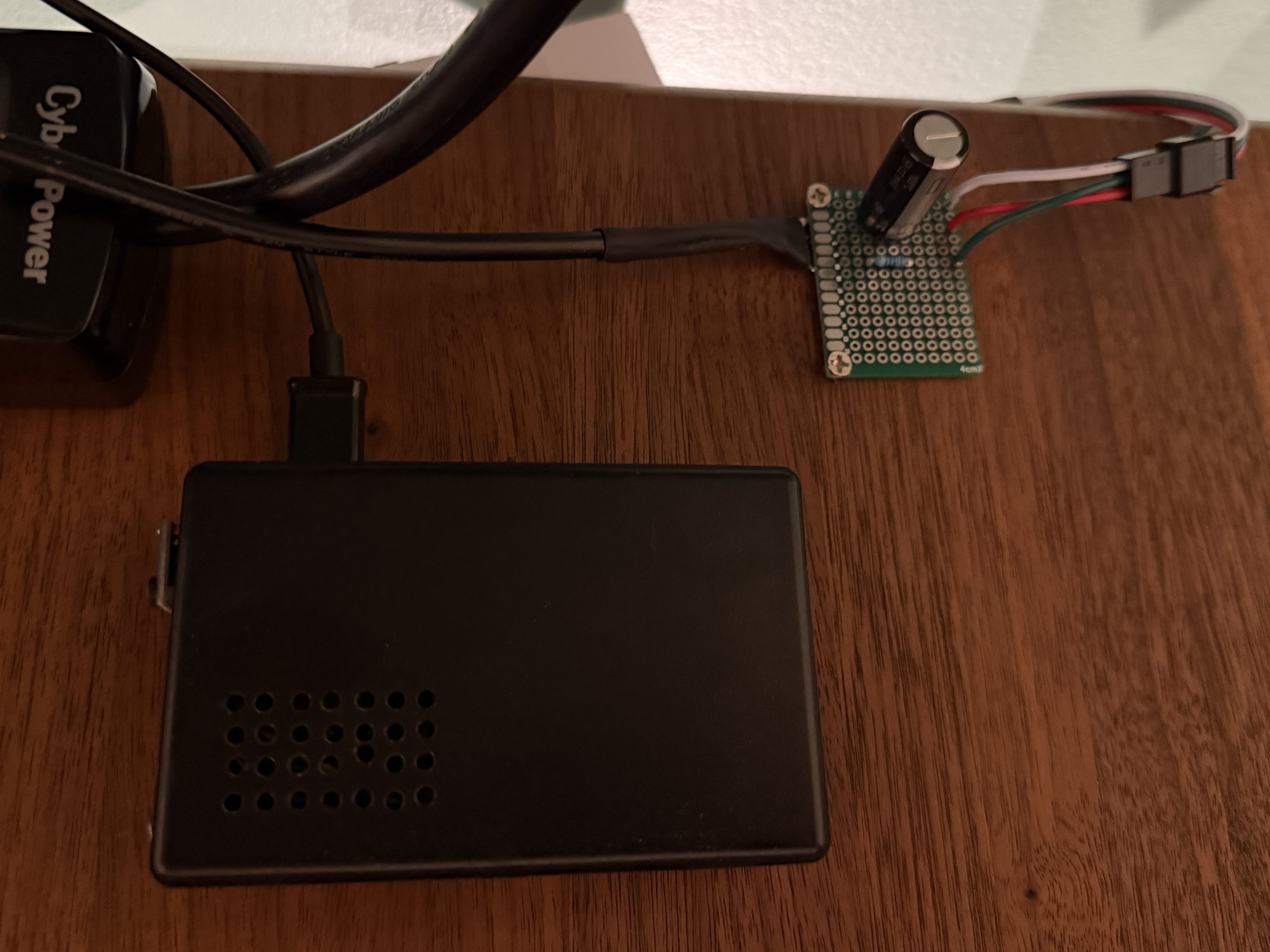
I picked up a 5m strip of adressable LEDs for my PyPortal device. The strip has 60 LEDs/m, which is double the density of the Neopixel strip I fried. To prevent future accidents, I tested improvements. Adding a 1,000 µF electrolytic capacitor protects the LEDs from a power spike and a 470Ω resister protects the first LED from data ringing.

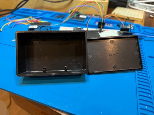
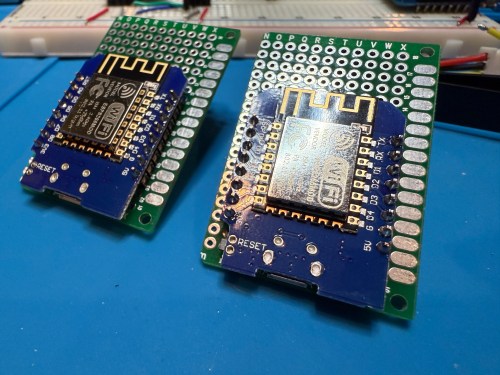
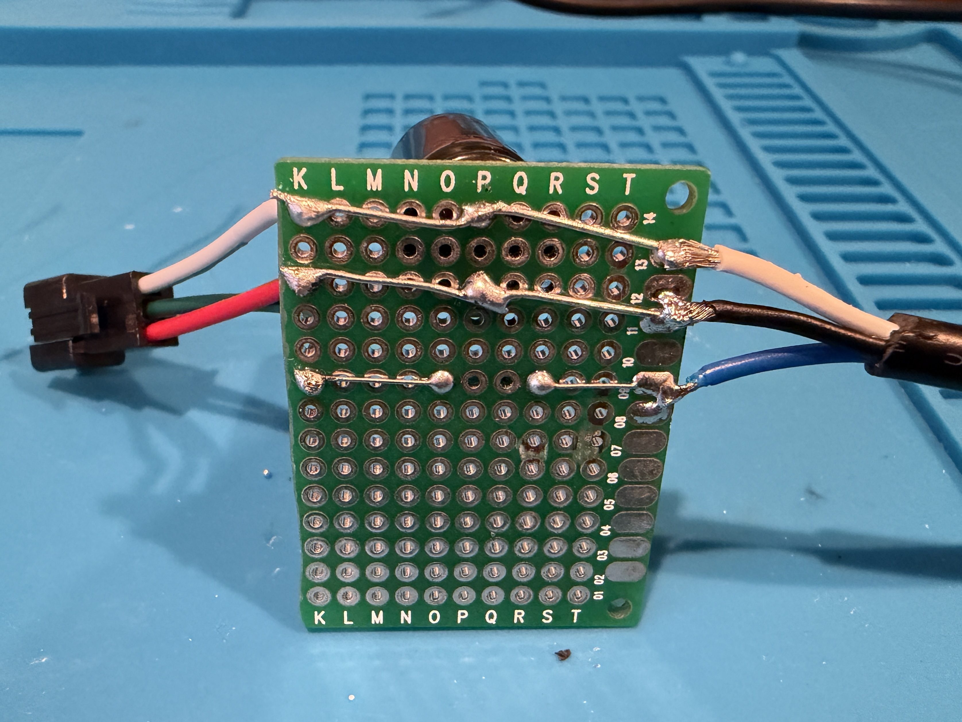
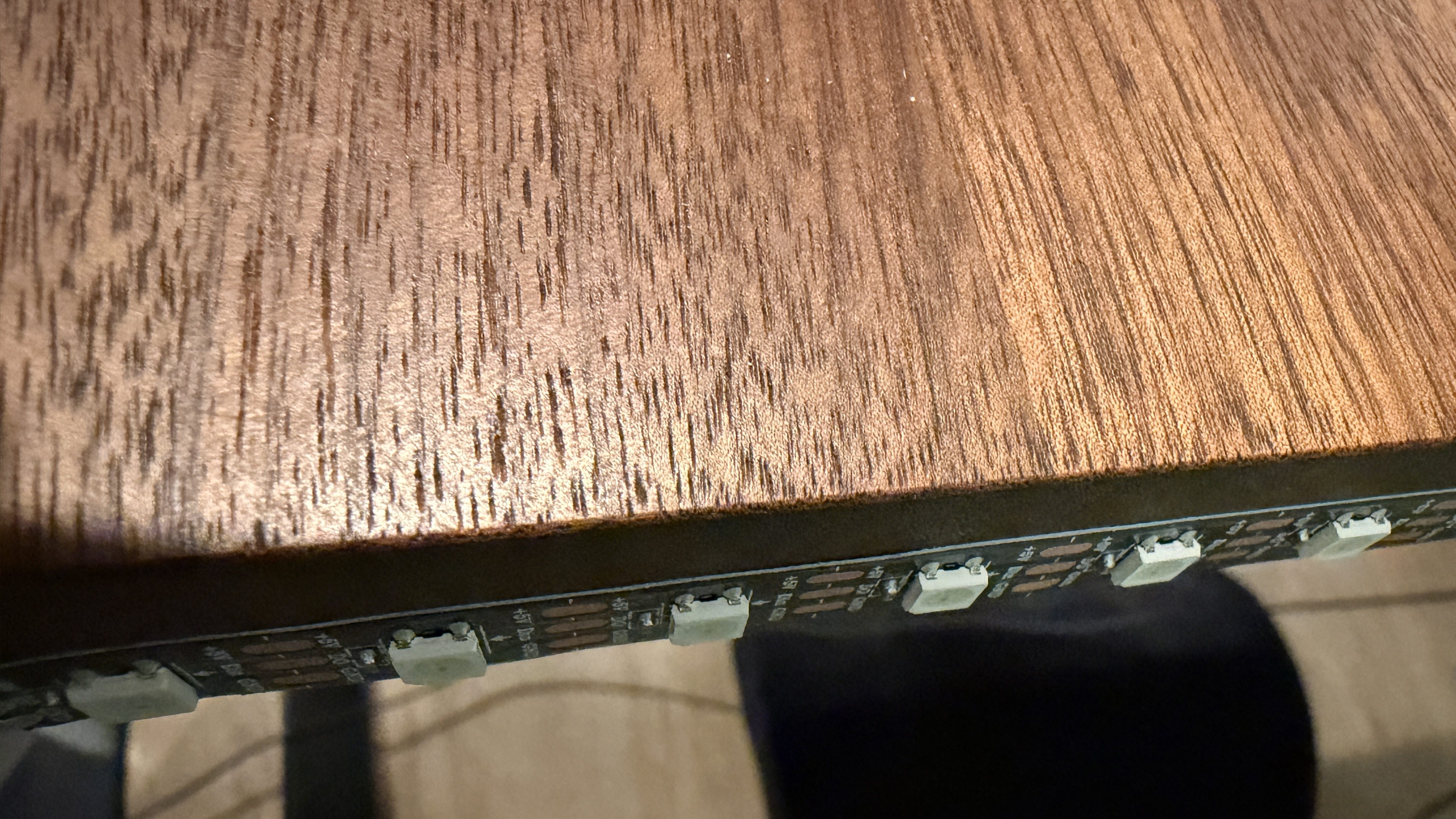
Everything worked great, so I cut off a section of 62 LEDs. Then I worked on a little board and better wiring.
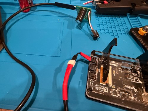
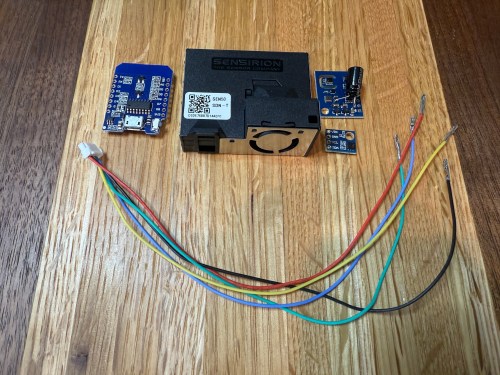
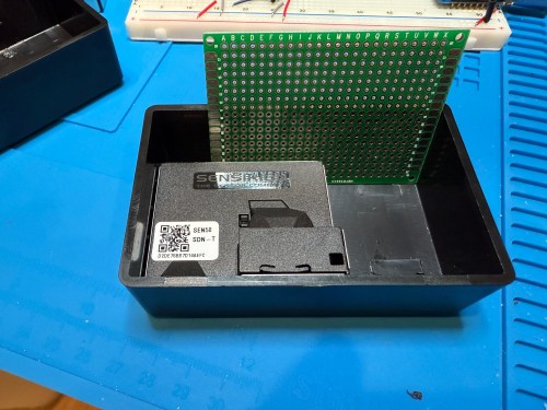
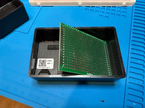
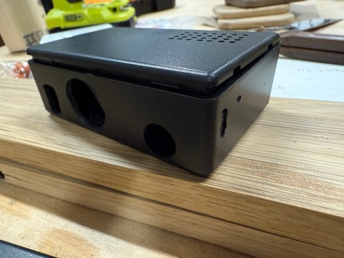
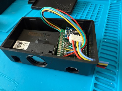
I didn’t trim the protoboard, so I could use the two holes to screw it to the undersize of my desk. This LED strip had an adhesive backing, which worked much better than the clips. I did a bit of cable management and also mounted the air quality monitor under the desk.
The code, which can be found on GitHub, got a bunch of small improvements:
- Updated the LED count
- Limited brightness to 50%, which is plenty and helps with power draw
- Adjusted the pulse functionality to account for the brightness limit
- Added a button to the interface which can be used to clear the LEDs
- When filling a color, reset the LED params global, so an animation won’t play on the next loop
- Tweaked the chase functionality to work better with the new LED density
- Changed the button success animation so the loop continues sooner
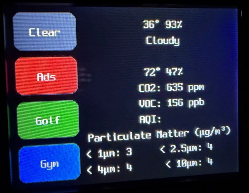
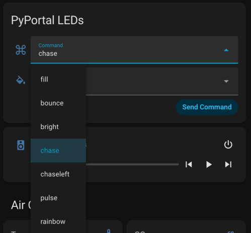
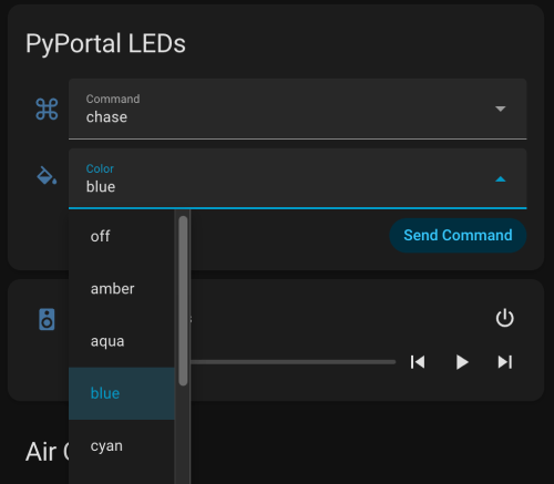
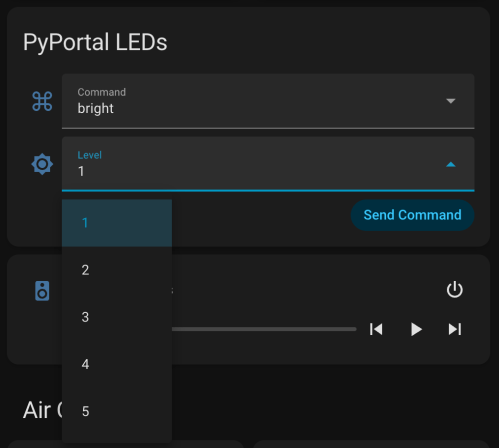
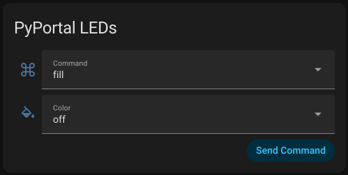
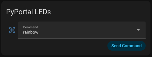
I had Google Gemini help me some stuff. First was to update the PyPortal firmware and CircuitPython version. Then update the code to make it compatible with CircuitPython 10.03. I also made an interface for my dashboard where I can select the different commands and options to send to the device manually instead of typing them in through Developer Tools -> Actions in Home Assistant.
Here’s a new demo video, so you can see how it works and what the lighting looks like.
Of course, the real power still comes from automations, where something happening around the house triggers Home Assistant to send commands to the device. Time to work on more of those. Almost a year later and this project is finally where I hoped it would end up.