The woman working the register said she had just put them out and there was actually a 3rd copy that was coming apart so she was going to glue it back together.
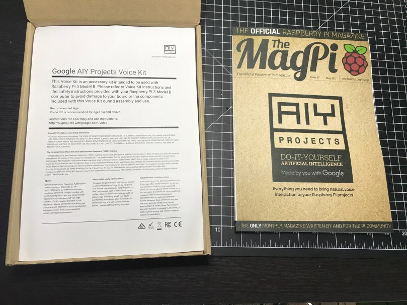
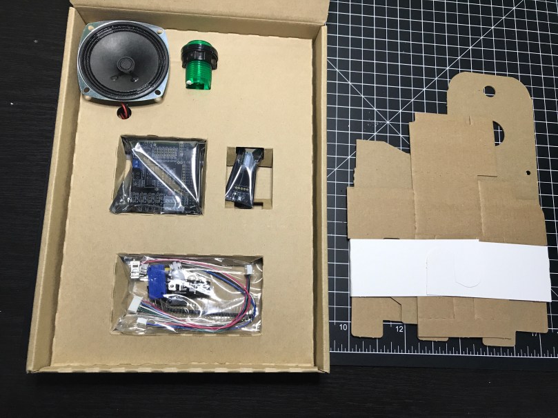
At $15 for a magazine, I don’t think you can really call this a “free” kit, but it’s still a good value. I don’t think I’ve ever “unboxed” a magazine before…
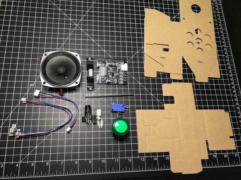
I love the emphasis on the maker here. Google is in this together with us.The actual magazine is the first thing you see when you open the box.A sheet with the typical warnings and instructions.The fun stuff! Various electronics parts and cardboard pieces to make a case.I guess the kits come with either a green, yellow, red or blue button.
This will be neat to mess around with. I’ve thought about turning one of my Pis into an Alexa type device to put in my office or bedroom and could easily do it now. If you have any project ideas involving voice, let me know.
Remember last week’s post about tearing apart a component switch to repurpose parts? I spent some time fooling around with IR after that. I thought it would be neat to recreate the basic functionality of switching between 3 devices. For my proof of concept the devices were simple the 3 status LEDs, but you can imagine the possibilities of turning on different devices or triggering processes run on a computer.
The new microcontroller I got is one I posted about a few months ago, called Puck.js. It has an IR transmitter built-in, so I wanted to use it to mimic a remote. Puck.js is pretty slick. It’s really neat being able to program a device in Javascript through a web IDE over Bluetooth Low Energy. No wires at all!
Propping a component into the GPIO pins like the author did doesn’t work for shit. You can’t get a solid electrical connection, especially if you bump it at all.
I kept getting Out of Memory errors on the device because the array would get really large really soon.
My next thought was to wire up to one of my other microcontroller that run Arduino, but the popular IR Library (IRLib2) doesn’t support the chips used in any of the boards I have. So over to a Raspberry Pi Zero. Pretty much every search result mentioned using Linux Infrared Remote Control (LIRC). May of the setup instructions I found were incomplete, but I was able to get things running by taking pieces from these two sites:
I’ll detail the steps that worked for me. Before I go down the software route though, I wanted to make sure the IR sensor worked. The only markings on the component are “71M4” and I have been unable to find a datasheet anywhere to match. Luckily these IR receivers are pretty standard and I had a pretty good idea of the pins from looking at how it was connected in the old device. I got the idea of hooking up a simple LED test circuit on the data pin from an Adafruit learn guide. Pin 1 is data, going into a GPIO pin on the Raspberry Pi (26 in my case), pin 2 is ground, and pin 3 is power (VCC). You may want to use the 3.3V pin on the Pi to provide your power instead of 5V just to be safe, or consult the datasheet for the IR sensor you’re using. Connect the anode of the LED to power and the cathode to pin 1 of the sensor using a 220 Ω (I used 200) resistor. When you press buttons on an IR remote, the sensor will send data through pin 1 and the LED will light up. Here’s a Fritzing wiring diagram for this test as well.
My test was successful! Now I was able to move on with some confidence knowing the part worked.
Install LIRC:
sudo apt-get update
sudo apt-get install lirc
Edit the /etc/modules file:
sudo nano /etc/modules
Add to the end:
lirc_dev
lirc_rpi gpio_in_pin=26
Change the pin if you’re using something other than 26. If you’re also going to do IR transmitting, you can add a space and gpio_in_pin=22 on that last line.
Press Ctrl + X, hit Y to say you want to save, and then Enter.
Edit the /etc/lirc/hardware.conf file:
sudo nano /etc/lirc/hardware.conf
Look for the DRIVER, DEVICE, and MODULES settings. Set them to match:
Press Ctrl + X, hit Y to say you want to save, and then Enter.
Edit your /boot/config.txt file:
sudo nano /boot/config.txt
Look for this line:
# Uncomment this to enable the lirc-rpi module
If you see it, remove the # from the next line and edit it to look like this (if your file doesn’t have it, add this to the end of the file):
dtoverlay=lirc-rpi,gpio_in_pin=26
If you’re going to do transmitting, also add this to the same line:
,gpio_out_pin=22
Change both pins to match whatever you’re using. Press Ctrl + X, hit Y to say you want to save, and then Enter.
Reboot your Pi:
sudo reboot
Now it’s time to use LIRC to record the codes sent by whatever remote you’re using. First you’ll want to see names you want to give your buttons. Run:
irrecord --list-namespace
Scroll through the list and make notes on all of the codes you want to use for your buttons. You’ll need the codes in a bit. Here was my list:
KEY_POWER
KEY_1
KEY_2
KEY_3
Stop LIRC:
sudo /etc/init.d/lirc stop
Use irrecord to create a configuration file for your remote. Follow the instructions carefully that come up on your screen. This took me several minutes for my remote with only 4 buttons.
Note: When it says Please enter the name for the next button (press to finish recording) is when you’ll need those codes above.
irrecord -d /dev/lirc0 ~/lircd.conf
When finished you’ll have a new file in your home directory. Take a look at it:
cat ~/lircd.conf
Mine looked like:
begin remote

  name  /home/pi/lircd.conf
  bits           16
  flags SPACE_ENC|CONST_LENGTH
  eps            30
  aeps          100

  header       9004  4474
  one           580  1666
  zero          580   542
  ptrail        578
  repeat       9006  2229
  pre_data_bits   16
  pre_data       0x61D6
  gap          107888
  toggle_bit_mask 0x0

      begin codes
          KEY_POWER                0x7887
          KEY_1                    0x40BF
          KEY_2                    0x609F
          KEY_3                    0x10EF
      end codes

end remote
Make a backup of the default LIRC configuration file:
You need to set up each button similar to what mine looks like:
begin
  remote = *
  button = KEY_POWER
  prog = pylirc
  config = KEY_POWER
end

begin
  remote = *
  button = KEY_1
  prog = pylirc
  config = KEY_1
end

begin
  remote = *
  button = KEY_2
  prog = pylirc
  config = KEY_2
end

begin
  remote = *
  button = KEY_3
  prog = pylirc
  config = KEY_3
end
Do a simple copy/paste and change the button and config for each entry.
Press Ctrl + X, hit Y to say you want to save, and then Enter.
Create a basic Python test program:
nano pylirc-test.py
Paste in:
#!/usr/bin/python

import pylirc

pylirc.init( 'pylirc', './pylirc.conf', 0 )

while ( True ) :
	s = pylirc.nextcode( 1 )
	command = None
	if ( s ) :
		for ( code ) in s :
			print( code["config"] )
Press Ctrl + X, hit Y to say you want to save, and then Enter.
Run the program:
python pylirc-test.py
Press buttons on your remote and if everything is working you’ll see the special name codes being output for each button you press.
Hit Ctrl + C to stop the program.
I already had all of the logic written for the buttons to work and switch LEDs, so it was easy to add in a little more code to take action when the appropriate IR codes were received.
Once I found the correct information, setup on the Pi was quite easy. A lot of steps, but easy stuff. Making the Puck.js duplicate my Infrared remote’s codes was a bit of a challenge. From the Puck.js Infrared tutorial I linked at the beginning I knew I needed to have an array of pulse lengths, but I didn’t have anything like that from the LIRC configuration. All I had was some hex values for each code:
KEY_POWER: 0x7887
KEY_1: 0x40BF
KEY_2: 0x609F
KEY_3: 0x10EF
Combined with another hex code for pre_data (0x61D6) from the lircd.conf file, I had more complete codes:
Infrared remote control signals from the LIRC remote configurations project, converted to Pronto Hex and Protocol, Device, Subdevice, and Function using lirc2xml…
BINGO! It had the Pronto Hex codes. I cloned the repo and started searching for my hex values. I found power, 1, and 2 matched up with codes used by something called a gigabyte TV. I plugged the codes into a program and they worked! I was only missed the code for button 3.
Then I spend way too much time still searching around. I knew enough about how IR worked and had 3 codes. I finally realized I should be able to figure out what changes to make in order to get my 4th and final code. I converted the hex values to binary:
KEY_POWER: 0x7887 = 111100010000111
KEY_1: 0x40BF = 100000010111111
KEY_2: 0x609F = 110000010011111
KEY_3: 0x10EF = 001000011101111
Then I started looking at the end of each array of Pronto Hex codes, because every code uses the same pre_data. I quickly determined an ON bit (1) was 003e, OFF (0) was 0013, and they were separated by 0017. I made the necessary adjustments and had all 4 buttons working with IR!
This IR journey turned out to be quite an adventure. I learned a lot, which was the point. My infrared-3-input-selector project on GitHub has the Python program used in the demo video, my pylirc config file, the simple pylinc test program, the Puck.js code, and even an Arduino sketch with the button and LED logic I created initially before realizing I needed to switch to the Raspberry Pi.
I bought the new Raspberry Pi Zero W along with the official Raspberry Pi Zero case. It’s really nice not having to worry about a wireless adapter. The addition brings my Pi family up to 7, which of course means it’s time for the letter G. Not a lot of pies starting with G. I ended up going […]
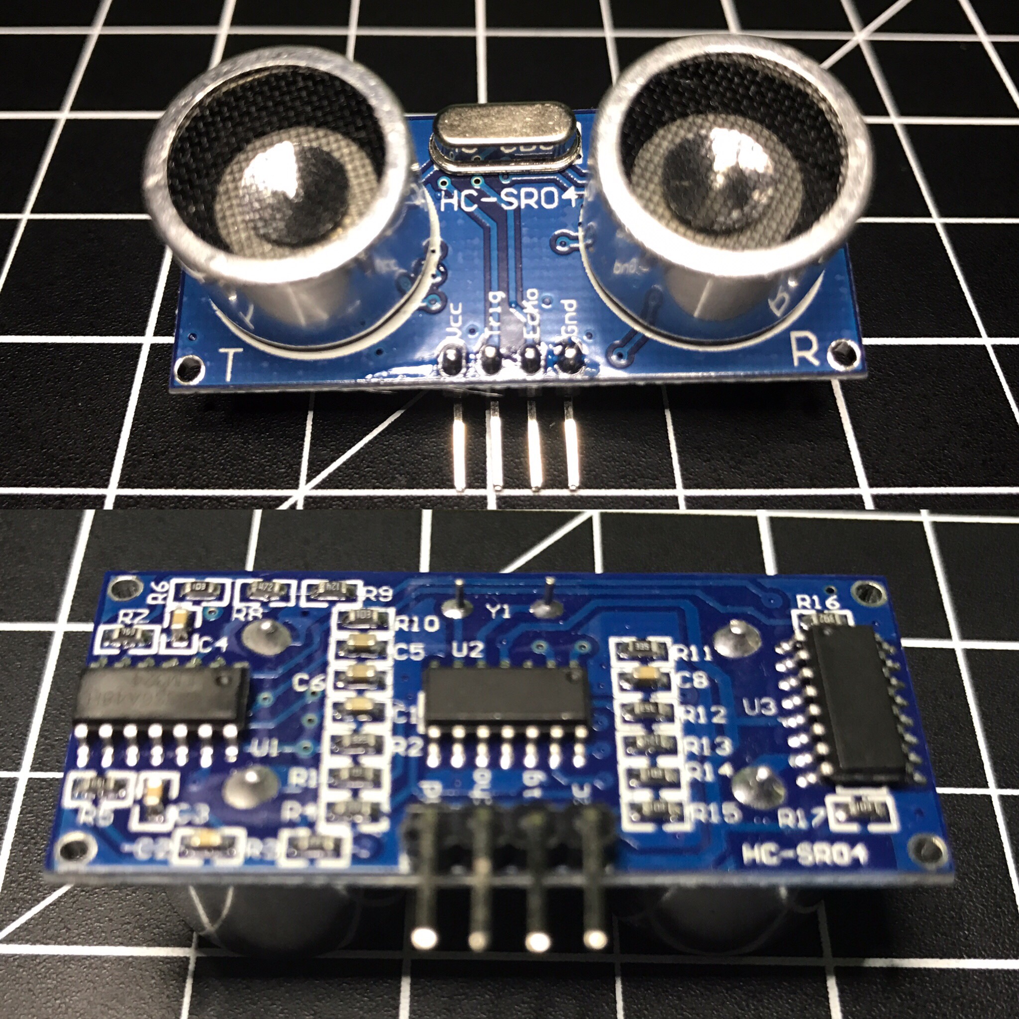
The HC-SR04 ultrasonic sensor uses sonar to determine distance to an object like bats do. It offers excellent non-contact range detection with high accuracy and stable readings in an easy-to-use package. From 2cm to 400 cm or 1” to 13 feet. Its operation is not affected by sunlight or black material like Sharp rangefinders are (although acoustically soft materials like cloth can be difficult to detect). It comes complete with ultrasonic transmitter and receiver module. Complete Guide for Ultrasonic Sensor HC-SR04
You can get the HC-SR04 from Amazon or various electronics shops for $3-5 or even under $2 if you buy packs of them. I got 2 of them in a parts kit I bought on Amazon and used one for Blog in a Box Paparazzi.
I was using the sensor to sort of detect motion, or more specifically when someone walked into a room. My prototype was set on a desk at about chest height about 1-2 feet after the doorway. While working on the project I ran into several challenges:
def read_ultrasonic() :
	# Make sure the trigger pin is clean
	GPIO.output( ULTRASONIC_TRIG_PIN, GPIO.LOW )
	# Recommended resample time is 50ms
	time.sleep( 0.05 )
	# The trigger pin needs to be HIGH for at least 10ms
	GPIO.output( ULTRASONIC_TRIG_PIN, GPIO.HIGH )
	time.sleep( 0.02 )
	GPIO.output( ULTRASONIC_TRIG_PIN, GPIO.LOW )

	# Read the sensor
	while ( True ) :
		start = time.clock()
		if ( GPIO.input( ULTRASONIC_ECHO_PIN ) == GPIO.HIGH ) :
			break
	while ( True ) :
		diff = time.clock() - start
		if ( GPIO.input( ULTRASONIC_ECHO_PIN ) == GPIO.LOW ) :
			break
		if ( diff > 0.02 ) :
			return -1

	return int( round( diff * 17150 ) )

def is_ultrasonic_triggered() :
	global prev_ultrasonic

	# Take 6 readings
	for i in range( 6 ):
		ultrasonic = read_ultrasonic()
		#Shift readings
		prev_ultrasonic = ( prev_ultrasonic[1], prev_ultrasonic[2], prev_ultrasonic[3], prev_ultrasonic[4], prev_ultrasonic[5], ultrasonic )

		if ( is_light_enough()
				and prev_ultrasonic[0] != -1
				and prev_ultrasonic[3] < ULTRASONIC_DIST and prev_ultrasonic[4] < ULTRASONIC_DIST and prev_ultrasonic[5]  ULTRASONIC_DIST and prev_ultrasonic[1] > ULTRASONIC_DIST and prev_ultrasonic[2] > ULTRASONIC_DIST ) :
			#print 'Ultrasonic: {0}'.format( prev_ultrasonic )
			return True

	return False

while ( True ) :
	if ( is_ultrasonic_triggered() ) :
		take_picture()
It worked alright, but triggered a little too often. About a week later I came across the Python package gpiozero, which makes it easy to work with a bunch of common Raspberry Pi GPIO components. I wrote an alternate version of BIAB Paparazzi using this package, which worked a bit better. It was so much simpler with gpiozero because it has built-in support for the HC-SR04. All I had to do was initialize the sensor and tell it what code to run when something in range was detected.
The neat thing about the gpiozero package is when you initialize a sensor it automatically starts taking readings, keeps the values in a queue, and does comparisons against an average. My code attempted to do something along those lines, but was much more rudimentary. As nice as this version sounds, it still triggered too often. You can find the complete code for both versions in the BIAB Paparazzi repo on GitHub.
I think I was pushing the limits of what the HC-SR04 is meant for. Most of the examples I’ve seen are people using these to detect approaching walls on a robot. The biggest issue I ran into was the inaccurate readings. For example I’d be getting readings of about 160cm and then out of nowhere it would return a distance of 80-90 cm, even several in a row at times.
At the end of the day there are reasons it’s such a cheap sensor. 😉 For a couple of dollars, what do you expect? I’m curious to try my code on a more powerful Raspberry Pi 3 and see if it works any better. Was the less powerful Pi Zero causing problems?
Happy Pi Day! I figured I better post something Raspberry Pi related today…
This weekend I played around with Blog in a Box which was recently released by our Tinker team at Automattic.
A quick and easy way of putting WordPress onto a Raspberry Pi.
BIAB ships with modules to use the Raspberry Pi camera and SenseHAT. I hadn’t used my Pi camera yet and had a fun idea to hack around with.
The camera module allows you to take a photo on a schedule by setting a period of minutes, hours, or days between each photo. I wanted to have a little more fun, so I wired some other electronics up to a Raspberry Pi Zero and wrote a little Python program.
The first electronic element was a simple button. Press it and a picture is taken. Next up was a photocell (light sensor). When the room quickly changes from dark to light, it’ll take a picture. Since the Pi doesn’t have analog inputs, I went with a neat technique of measuring the sensor as a resistor used to ‘fill up’ a capacitor. The last element was an ultrasonic sensor I haven’t used yet either. It measures the distance to an object in front of it, so I’m kind of using it as a motion detector. Walk in front of the sensor and a picture is snapped. Due to mismatched voltages on the PI’s GPIO and the output signal of the rangefinder, I had to use some resistors to create a voltage divider circuit.
To create visual feedback I wired up an LED for each of these 3 components. When one of the components triggers a photo, the associated LED lights up until the process is complete.
I named it Blog in a Box Paparazzi. Of course the code and wiring info are available on GitHub. Should be easy to adjust if you have other sensors, buttons, switches, or whatever you want to trigger photos. Let me know if you try something different.
Almost a full 24 hours of DNS activity on my home network. Nine of the top 10 domains queried were for home automation services, so if were to remove those from the stats, Pi-hole blocked over 10% of requests. If you want to run your own Pi-hole server, check out my step-by-step guide.
With all of the Raspberry Pis I have (now up to 6 after adding “flapper”), I wanted to get a bunch of data in Home Assistant (yes, I’m still working on a larger home automation post) and have an easy way to reboot or shutdown each computer.
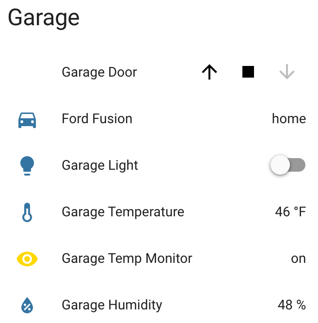
I wrote a little app which runs as a service on each Pi. Here’s an example of what shows up in Home Assistant.
The Python app and sample Home Assistant configurations are in my home-assistant-pi project on GitHub. Of course it’s all Open Source.
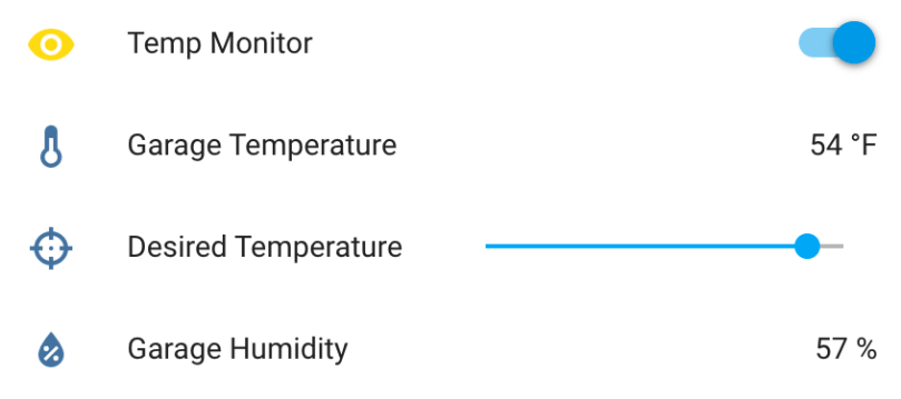
I made some updates to the Garage Temperature Sensor & Monitor. I didn’t like how the desired temperature was set via the app’s configuration file, so I moved it to a slider control in Home Assistant and updated the LCD to always show the value. Only being able to enable/disable monitoring via the device’s button also wasn’t great. I converted the binary sensor I was using to flag monitor mode in HA to a switch control and moved the actual monitoring logic from the Python app to HA automation. Everyhing is updated on GitHub.
Info and controls in Home AssistantCustom temperature and humidity monitor
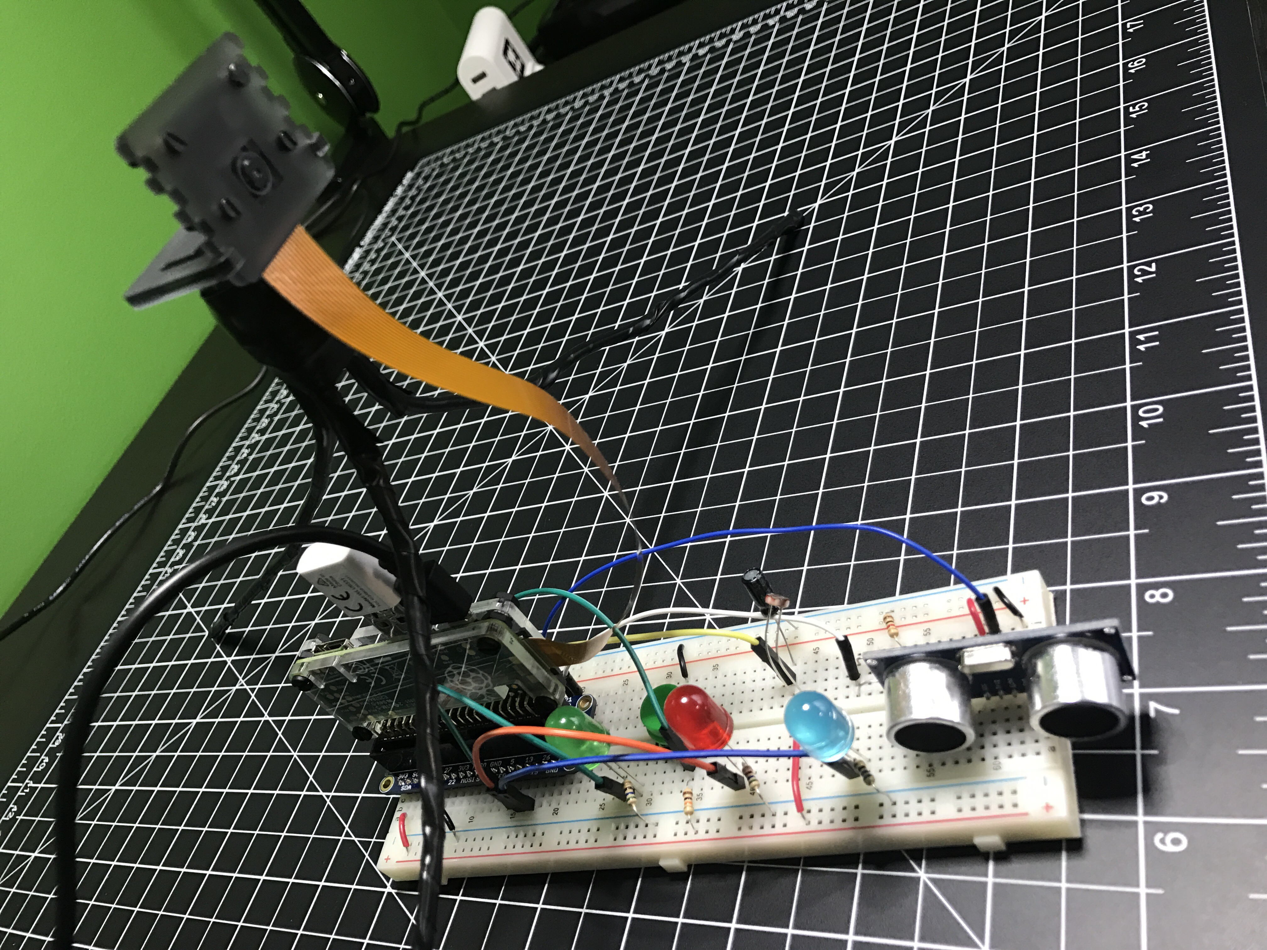
I’ve been working on this project here and there for a few weeks, with most of the early work being experimentation. Everything is now up and running and it’s “deployed to production” so to speak. This was my prototyping setup…
After wiring everything together and repurposing a cardboard box, here is a short video to show the final product.
A few notes on how it works:
The button toggles monitor mode. The LED inside the button indicates if Monitor mode is on/off.
When monitor mode is on and the desired temperature is reached, I get a notification.
I should have shown the knob, but all it does is adjust the LCD’s contrast.
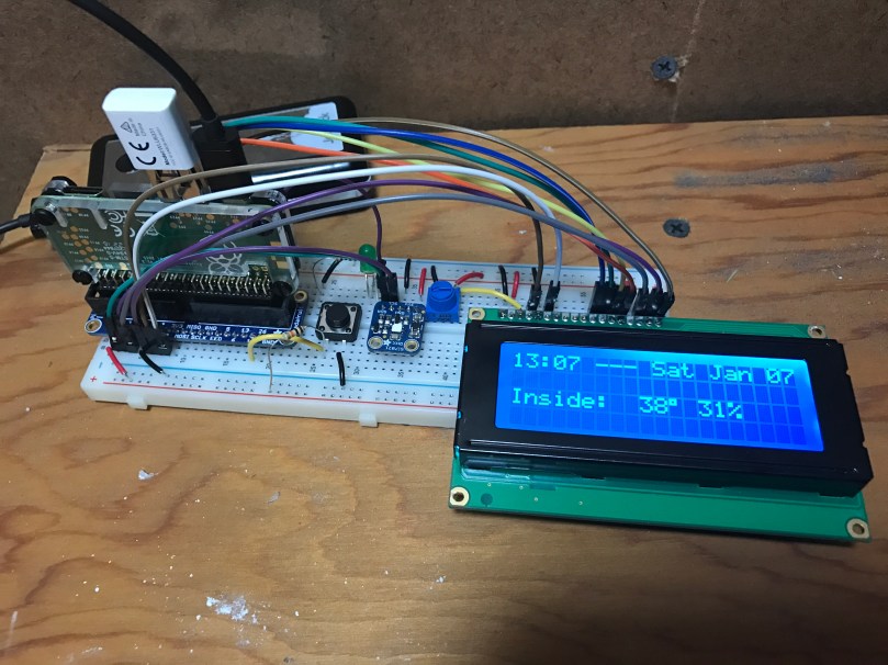
The thing on the top left of the box is the sensor chip for reading temperature and humidity. Originally it was inside the box behind a little window there but it was picking up too much heat from the Pi and LCD in there.
The backlight color of the LCD is based on the measured temperature and updates each time new temperature is read. Anything 32° Farenheit and below is blue, 80° and above is red, and everything in between is based on where it falls within that 32-80 range. As you can see in the example, 48° is a lighter blue. A few degrees warmer and I think it would have started to look more green.
Outside temperature/humidity is pulled in from the Dark Sky data in my Home Assistant setup (which I’ll post about soon).
Really happy with how things turned out. The Pi I wrote this in Python and it’s all available as home-assistant-temperature-monitor on GitHub if you want to make your own or use some of the code for your own project. There is also a list of all the components used.
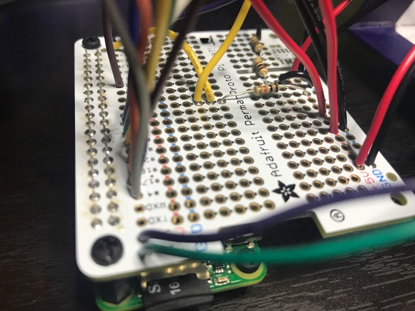
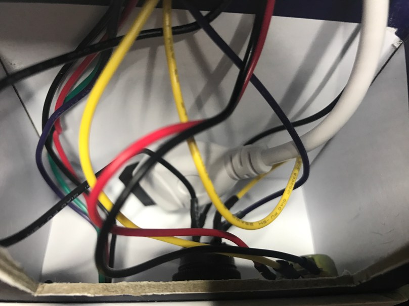
Here are some pictures I took while assembling the enclosure/box.
Making sure the Pi and attached Hat fit right after drilling the holes. Seemed like there was so much room at this point.Everything soldered to the HAT. Amazingly I didn’t make any mistakes and everything worked on the first try. A good prototyping setup, having pictures of my final prototype, and keeping a list of where everything connected was invaluable.The Raspberry Pi, Hat, LCD, USB cables to power and WiFi, and all of the other wiring jammed in! Reaching inside to get things screwed through the box wasn’t easy.There is a lot more room in the other part of the box where the sensor, button, and knob are. Nice for the WiFi adapter and cable to come across and have some room.
Mom gets what Mom wants. The necessary parts came in to build Mom’s Raspberry Pi-Hole server, so I thought I’d take the extra time to keep track of every step, trying to make it as easy and low-cost as I could. This meant not attaching a monitor or keyboard through the entire process. Hopefully someone will benefit from this guide. It looks long and scary, but I tried to be as thorough as possible. Nothing here is particularly difficult if you can follow directions.
Make sure the microSD card is class 10, because it’s faster and don’t be afraid to go for 16GB since they are so cheap. Adafruit sells a budget pack which includes everything above except the WiFi adapter. If you don’t want to use WiFi, you could get something like this Ethernet Hub and USB Hub.
I also recommend some type of case. It may be small, but it’s still a computer with electrical components. 😉 I bought the Adafruit Raspberry Pi Zero Case this time around, but I don’t like how loose the GPIO slot cover is. Three cases I use with my own Zeros and like (ordered by preference) much better are:
Download ApplePi Baker and extract the app from the zip file.
Plug the SD card into your computer, probably via a USB card reader or SD card adapter.
Launch ApplePi Baker. It’ll ask for your MacOS user password.
Select your SD card on the left side.
Uncheck Auto eject after successful restore.
Click the Restore Backup button and browse to select the Raspbian file you downloaded. Once selected it’ll start writing to your SD card. It should look like this…
While that is running, save this sample wpa_supplicant.conf file. If you set Format to All Files you can remove the .txt without MacOS adding it back on. This file needs to be named exactlywpa_supplicant.conf.
Open the file in TextEdit. Replace YOUR_SSID with the name of your WiFi network and YOUR_PASSWORD with your WiFi password. Save the file.
When ApplePi Baker is finished click OK and quit the app.
Copy the updated wpa_supplicant.conf file to the SD card.
Open the Mac’s Terminal app.
Type cd /Volumes/boot and hit Enter.
Type touch ssh and hit Enter.
Quit Terminal.
Eject the SD card via Finder and then remove it from your computer.
Step 3: Prepare the Raspberry Pi
Slide the SD card into the slot on your Pi Zero.
Put the Pi Zero into your case if you have one.
Plug the USB cable and WiFi adapter into the micro USB port labeled USB. Hint: it’s not the one on the end. You should end up with it looking like this…
Now you’re ready for power! Plug your power supply into the other micro USB port (nearest to the edge) and into your power source.
You should see some activity from the green light (labeled ACT) near the power connection.
Step 4: Access the Pi
If you did the second half of step 2 correct, the Pi should have been able to connect to your WiFi network. Give it 1-2 minutes to go through the entire boot process.
Open the Mac Terminal app again.
Type ssh pi@raspberrypi.local and hit Enter.
Using the IP address for SSH may work better for you ssh pi@192.168.1.123 but you’ll need to find it in the DHCP list in your router’s admin.
If everything worked, it’ll connect and you will be asked if you want to continue. Type yes and hit Enter.
Then you’ll be asked for the password. Type raspberry (you won’t see any characters on the screen) and hit Enter. This should log you in and set you at the command prompt…
Step 5: Run Software Updates
Type sudo apt-get update and hit Enter.
When it finished you’ll be back on the command prompt. Type sudo apt-get upgrade and hit Enter. When it asks Do you want to continue? [Y/n], type y, hit Enter, and wait.
Step 6: Configure Your Pi
Type sudo raspi-config and hit Enter.
Any mouse/trackpad devices won’t work in here, so get used to the tab, Enter, and arrow keys.
Change User Password. Remember it!
Choose Advanced Options and then Hostname. Set a new “computer name” instead of the default raspberrypi. When you’re done and back to the main menu, select Finish and perform the reboot.
You’ll lose your connection when the Pi is rebooting. Terminal will send you back to the local Mac command prompt. Wait 1-2 minutes.
Step 7: Install Pi-Hole
Connect back to your Pi via ssh, but this time you need to use your new hostname. For example if I had set nickspi the new command I would type is ssh pi@nickspi.local. You’ll be prompted again to continue and enter the password. Do both.
Type curl -sSL https://install.pi-hole.net | bash and hit Enter.
Accept all of the defaults when prompted during installation.
At the end it’ll give you a bunch of information on an Installation Complete! screen. Make note of the IP address and admin password. Hit Enter.
It’ll do a little more and then send you back to the command prompt along with providing all of the information again.
Change the password right away with the command: pihole -a -p PASSWORD_YOU_WANT_TO_USE
Enjoy your mostly ad-free browsing and faster network!
Step 10: Notes
It’s not advised to unplug the Pi from power when it’s running. You could corrupt the SD card. SSH in (you’re a pro by now) and issue the shutdown command:
sudo shutdown -h now
Wait about a minute before unplugging power (make sure the activity light has been off at least a few seconds). You can also issue a restart command if you need to:
sudo reboot
Periodically it’s a good idea to update the software:
With all of that said… if you plan to run anything else on this server, I recommend going with more power, probably a Raspberry Pi 3 Model B. The Zero I originally used wasn’t enough to handle Home Assistant and Homebridge running on the same machine.


 I got
I got 

 Happy Pi Day! I figured I better post something Raspberry Pi related today…