
iPhone X
I spent all of last week with about 540 Automatticians. For an introvert like me it’s a challenging and exhausting week. When meeting new people each day we often repeat the same conversations.
How is your week going?
What team are you on?
How long have you been working here?
It’s all a bit awkward (but good) for me, being someone who doesn’t enjoy small talk.
These conversations and interactions may not have been the hardest part of the week though. We tried something new at this year’s Grand Meetup, called Homeroom. Each person in the company was split off into a group of about 25 people we met with for an hour on 4 of the days. At the beginning of each hour, the leads in the room had us place our phones in a drawer or box so we could focus on the group and getting to know people.
Andy said, “It feels like someone cut off my arm.”
I think I’m pretty good at not constantly pulling out my phone in social situations, but not having the option gave me an uneasy feeling.
I asked my family to give me old electronics instead of throwing things out. My sister gave me this phone alarm clock, so I tore it apart. I was able to salvage some cool parts from it. For me, it’s not about trying to save money, because I could order brand new modern parts for […]
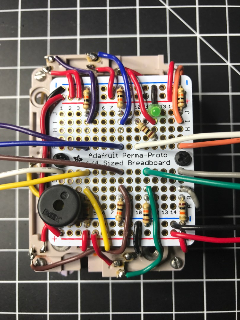
Go back and read Part 1 if you want to the full story on this little project. I did decide to get rid of the PCB on the old phone keypad. Good thing I’ve been getting a lot of desoldering practice. In order to remove the PCB, I first had to remove the wires I had added to the column and row contact points. That was easy and getting the PCB off was a pretty smooth process as well.
Now that I didn’t have the PCB to carry power and ground around everywhere, I had to solder in my own wires. I also had to solder back in all of my connection points to provide the outputs I’d feed into a microcontroller (I used an Adafruit Feather 32u4 Basic Proto).
Once all of the wires were in place and then connected to my microcontroller I wasn’t getting expected results from a simple little program I wrote to display the values. Took far too long for me to remember I needed to use pull down resistors to prevent floating values. I put 10k Ω resistors in each of the circuits…

Output from the pins couldn’t get any better…

I loaded an example from the Arduino KeyPad library, which gave me very weird behavior. After looking at the underlying code, I realized it wanted the outputs of the keypad to be HIGH when a key was not pressed and LOW when it was. Well, my circuit was doing the opposite, so I had to have to invert everything. I didn’t have any inverter ICs, so I used NPN transistors to create an inverter circuit on each output.

Progress. Now I was able to get the library to correctly recognize some key presses. 95% of the time it seemed to think everything was coming from column 1 (1, 4, 7, *) though. The library comes with a MultiKey example. When I ran that, it was reporting every key on the row as being pressed. WTF?!
For the life of me I could not figure out what caused this. I checked wires, measured voltages, did continuity tests, resoldered connections, changed boards, used different GPIO pins, and countless other things. Nothing made a difference. My own code was working beautifully though. Eventually I gave up on the library. It wasn’t worth the effort and I was out of ideas.
Update: Later on I went back and read the KeyPad library code again because it was bugging me. Turns out these keypads don’t actively read the column pins like they do the row pins. My assumptions about how they worked was very wrong because I hadn’t read far enough into the code before. When checking for key presses, typical keypads iterate through the columns to send a pulse which feeds over in to the rows, which are then read in. How a Key Matrix Works has a pretty good explanation with visuals. If I get my hands on another similar keypad maybe I’ll try to recreate this functionality.
I rewired everything to use the pull down resistors again (video of soldering). A huge benefit of the decision was it drastically simplified my circuitry. This would save me 49 solder points! I probably would have needed to use a half-size perma-proto board instead of the 1/4 size I ended up using.
I decided to put in a piezo buzzer to add sounds. I also used a tiny LED, which I had salvaged from some old computer speakers, to show when power is switched on to the backlight.

I tried a couple of different methods of producing touch tones (DTMF) to match up with each key, but with the microcontroller I’m using and the small piezo buzzer, the sound was terrible. I would need something a little more capable I think.
Here’s a demo video.
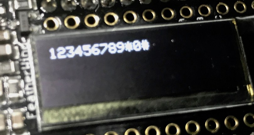
Hard to see the OLED screen in the video, but I was only using it to output each key press. Something like this…
All of the code and Fritzing wiring are available in my phone-keypad repo on GitHub.
I even went out of my comfort zone and did a quick share of this on Adafruit’s Show and Tell. If the video doesn’t start at the right spot you can skip ahead to the 12:42 mark. Going back to watch, my demo kind of sucked since it’s hard to hold something up to the Mac camera and push buttons at the same time.
Update: Continue on to Part 3, where I create a matrix of buttons to act as a keypad.

A couple of weeks ago I came home to find this 2017/2018 Yellowbook thrown in my driveway. How is a physical phone book still a thing?
Remember the white pages where you could look up the phone number for anyone in your area? Seems like decades ago, though I couldn’t tell you the last time I called a personal land line.
 I’ve been on a kick tearing apart electronics. In addition to the switch I got a bunch of parts from, I’ve tore into a lamp and some old computer speakers. When I found an old telephone (it has a date of 5/30/1980 printed on it!) in my basement I knew I had to see what was inside. The previous owners left it in a storage room and I have no idea why I never pitched it. I didn’t take a picture before taking a screwdriver to it, but it looked exactly like the photo on the right.
People have been hacking phones for a long time. Perhaps the earliest and most well-known was the Steves (Jobs and Wozniak) using a blue box on payphones. I’m nowhere near that level, but you have to start somewhere right? I pulled the ringer, speaker, and microphone out of it. I haven’t messed with these yet.

The part I thought would be neat to work with was this keypad.
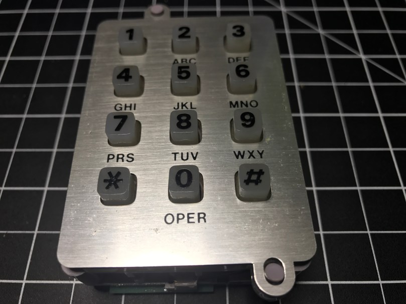

It was a bit of a process figuring out how to tap into this thing. Eventually I realized what these contact switches on the sides were for.

 There are seven of them. The top has two and the bottom has one, which correspond to the 3 columns of keys on the grid. Then the left and right sides each have 2, which match up with the 4 rows of keys.
This row/column grid system is still how we reference the individual keys on keypads like this. Arduino has a Keypad library for working with modern keypads like one sold by Adafruit.
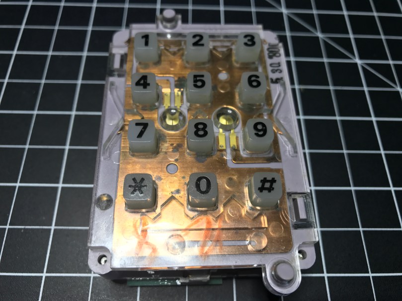
I figured out I could solder wires to the contacts points connected to each of those switches. I was in! From the way the keypad was connected to the rest of the phones circuitry I knew the screws were an important piece to tie it all back into the entire system. After some trial and error I determined which screws should be used for power (red wire) and ground (black) in order to get useable data out of the 7 switch contact points. The other 3 screws also connect to power. I was using alligator clips on those, but disconnected them for the picture.

Something isn’t quite right about the screw connections though. When I connect them the opposite way, flopping to have 1 power and 4 grounds, the backlight on the keypad works, but the readings from the soldered contact points are useless. With them connected this way, I don’t get the backlight, but I get data I can make sense of. There is probably something obvious I’m missing about how this all works together.
Unfortunately for me, the output from the contact points isn’t digital (limited to on/off), so I couldn’t use the Arduino library. It would have made things so much easier. It’s not surprising though, since this piece of technology is almost 40 years old!
I was able to get some code mostly working. Detecting the column of a button press was pretty straight forward and works great. Rows detection is another story. I’m reading in analog values and using sampling along with standard deviations to determine which row’s value is unlike the others. Well, the first row always reads a pretty high value, when a key on any row is pressed. The values for the other rows fluctuate as expected. When that first row is high, I’ve attempted to also look for a high value from another row, but it triggers the wrong row too often.
Demo time…
Even making this short little video, which took at least 5 takes, there was a false trigger for pressing 1 and many key presses not being recognized. Not useable.
I have a hunch the screw connections are responsible, at least in some part, for sending DTMF signals, also known as Touch-Tone. I don’t really care to get in the business of decoding these. This is precisely why I was hoping I could detect useful output from each of the row and column contact points.
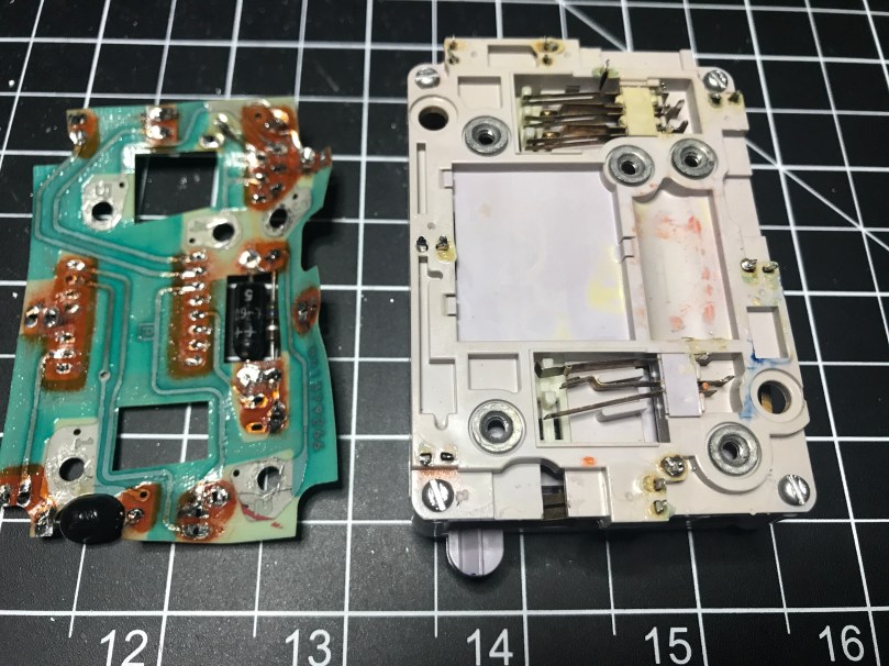
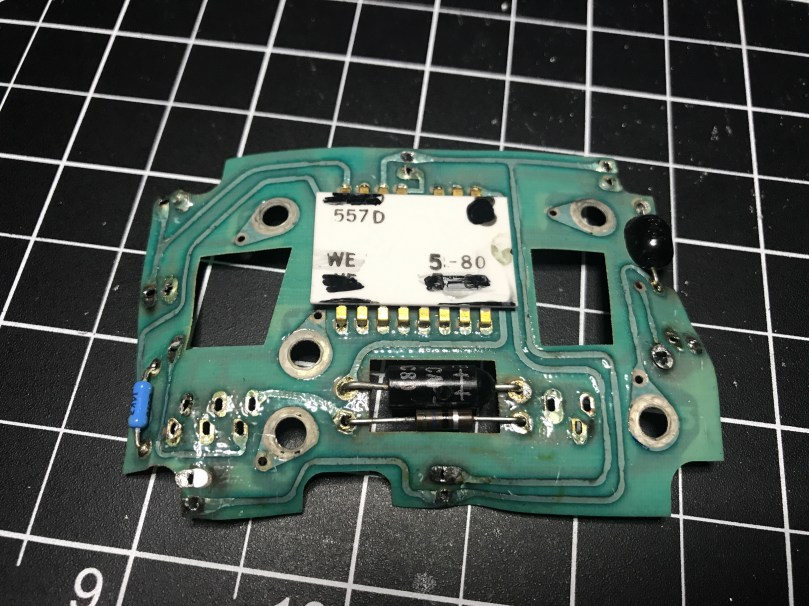
I pulled apart the unit even more and discovered a Western Electric 557D is the brains of the operation, but it’s so old there doesn’t seem to be a datasheet online for it. What I’m going to do is remove the PCB and wire up everything on my own. Then I can easily get on/off as digital values from the columns and rows and make sure the backlight works. Stay tuned…
Update: Read Part 2
Please stop playing with your phone when you are driving. It only takes a second to drift out of your lane or not notice something in front of you. Don’t become a statistic. Don’t end someone else’s life.
The Facebook notifications, random texts, and Snaps can wait a few minutes until you reach your destination. If something is so important it requires immediate attention, pull off the road, park, and respond. Or use a hands-free call to respond instead of typing on the phone.
If you are good at keeping your phone tucked away, convince at least one other person to do the same.
Updated my iPhone to 2.1 and it found about 4 new voicemails that I never received. Now I feel like an ass for not calling people back because they didn’t leave a VM. They did, but I didn’t get them until today. Isn’t technology great?
Why didn’t I hack my iPhone a long time ago? It’s like a brand new phone all over again.
Does a fax machine keep dialing your phone number? I’ve had this happen several times at work and just had it happen a few minutes ago. If you are on phone system, this fix works great. Answer the phone and quickly transfer the call to your office’s fax number. The office fax machine will receive […]
