Creating an ESPHome Remote Control Device with Infrared & Radio Frequency

In order to automate the processes of getting the golf sim ready to play and shutting it all down when finished I needed to create a remote control device. I’m using Home Assistant (HA) to run my home smart system (more posts to come), but two things involved with the golf sim aren’t connected to the network:

The projector has an infrared (IR) remote and the light has a radio frequency (RF) remote. I’ve done some things with IR and still had a stash of IR LEDs (for transmitting) and receivers. I’ve never attempted any RF stuff, so I ordered a 5 pack of 433mhz wireless RF transmitter and receiver pairs.

Since I’m using HA, I let ESPHome handle all of the main programming. All I had to do was wire everything properly and get the configuration correct. I made use of an old ESP8266 NodeMCU microcontroller and worked on the IR aspect of the project first.

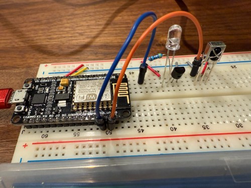
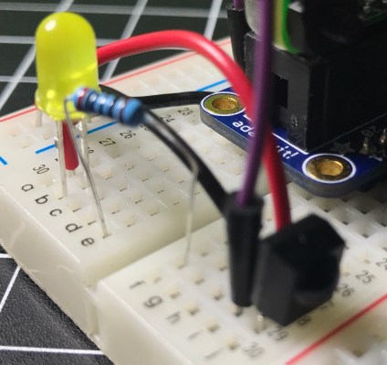
When I took the picture I was using a 470Ω resistor, which I eventually switched to 100Ω, to increase the strength of the IR signal. The transistor is a PN2222A. Here’s the ESPHome configuration:

esphome:
  name: golf-remote
  friendly_name: Golf Remote

esp8266:
  board: nodemcuv2

logger:

api:
  encryption:
    key: "xxxxxxxxxx"

ota:
  - platform: esphome
    password: "xxxxxxxxxx"

wifi:
  ssid: !secret wifi_ssid
  password: !secret wifi_password
  manual_ip:
    static_ip: x.x.x.x
    gateway: x.x.x.x
    subnet: 255.255.255.0

remote_receiver:
  - id: GOLF_IR_RX
    pin:
      number: D1
      inverted: True
      mode:
        input: True
        pullup: True
    dump: all

remote_transmitter:
  - id: GOLF_IR_TX
    pin: D2
    carrier_duty_percent: 50%

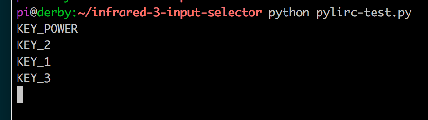
I used the receiver to intercept the codes sent by the projector’s actual remote when pressing the Power, Input, and OK buttons. Then I created some buttons.

button:
  - platform: template
    name: Projector Power
    on_press:
      - remote_transmitter.transmit_nec:
          transmitter_id: GOLF_IR_TX
          address: 0x3000
          command: 0xFD02
  - platform: template
    name: Projector Input
    on_press:
      - remote_transmitter.transmit_nec:
          transmitter_id: GOLF_IR_TX
          address: 0x3000
          command: 0xFB04
  - platform: template
    name: Projector OK
    on_press:
      - remote_transmitter.transmit_nec:
          transmitter_id: GOLF_IR_TX
          address: 0x7788
          command: 0xE619

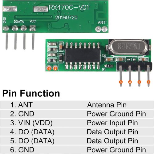
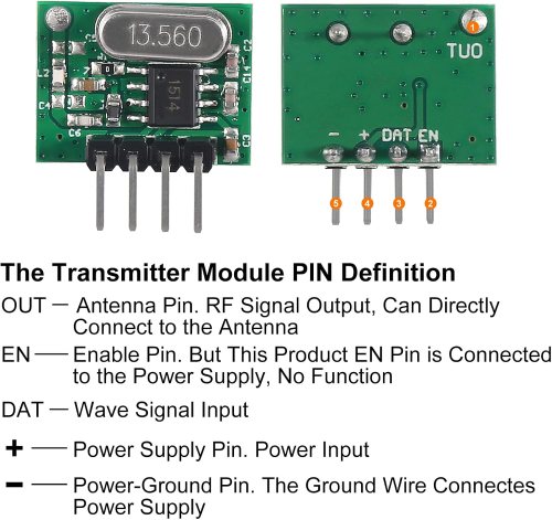
It all went very smooth. Next I connected the circuits for the RF components, which was straightforward. Here are the pinouts from the Amazon product page.

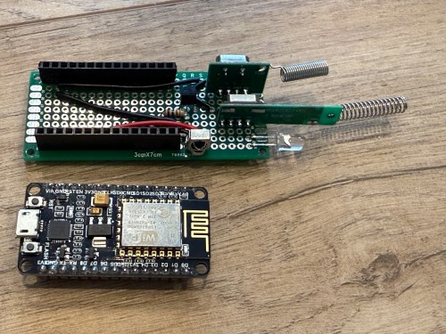
I soldered on the antennas (smaller one to the transmitter) and connected everything on the breadboard.

By using examples from the documentation I was able to intercept RF codes.

When I tried to recreate those codes through the transmitter the results weren’t matching up and the spotlight wasn’t responding. It took some trial and error to configure the various parameters of the receiver. Here’s the end result, with the combined configuration for IR and RF.

esphome:
  name: golf-remote
  friendly_name: Golf Remote

esp8266:
  board: nodemcuv2

logger:

api:
  encryption:
    key: "xxxxxxxxxx"

ota:
  - platform: esphome
    password: "xxxxxxxxxx"

wifi:
  ssid: !secret wifi_ssid
  password: !secret wifi_password
  manual_ip:
    static_ip: x.x.x.x
    gateway: x.x.x.x
    subnet: 255.255.255.0

remote_receiver:
  - id: GOLF_IR_RX
    pin:
      number: D1
      inverted: True
      mode:
        input: True
        pullup: True
    dump: all
  - id: GOLF_RF_RX
    pin:
      number: D6
      mode:
        input: True
        pullup: True
    dump:
      - rc_switch
    tolerance: 50%
    filter: 250us
    idle: 4ms
    buffer_size: 2kb # only for ESP8266

remote_transmitter:
  - id: GOLF_IR_TX
    pin: D2
    carrier_duty_percent: 50%
  - id: GOLF_RF_TX
    pin: D6
    carrier_duty_percent: 100%

After using the remote_receiver instances to get the button press codes I needed, I commented out that section of the code. If I ever need to add more functionality to my remote, I can enable the receivers at that point. Here are the button codes for the spotlight.

  - platform: template
    name: Spotlight On
    on_press:
      - remote_transmitter.transmit_rc_switch_raw:
          transmitter_id: GOLF_RF_TX
          code: '111001000000100100000011'
          protocol: 1
          repeat:
            times: 10
            wait_time: 0s
  - platform: template
    name: Spotlight Off
    on_press:
      - remote_transmitter.transmit_rc_switch_raw:
          transmitter_id: GOLF_RF_TX
          code: '111001000000100100000001'
          protocol: 1
          repeat:
            times: 10
            wait_time: 0s
  - platform: template
    name: Spotlight Green
    on_press:
      - remote_transmitter.transmit_rc_switch_raw:
          transmitter_id: GOLF_RF_TX
          code: '111001000000100100000111'
          protocol: 1
          repeat:
            times: 10
            wait_time: 0s

Then I was able to use both sets of buttons in scripts, which can feed to Alexa for voice commands.

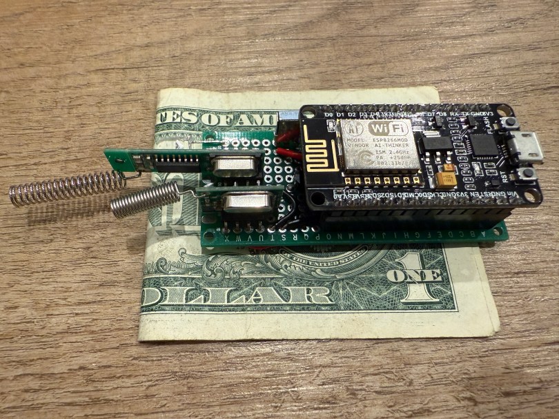
Once everything was tested I wired and soldered a more permanent circuitboard. I included a folded dollar bill for scale.

I was planning to mount it in the ceiling, but the IR was having trouble, because the projector’s receiver faces the ground. Mounting it to the side of the PC cart worked great.

This was a lot of fun!

Update: Less than a week later I’ve already modified it, by adding a DHT22, which reports temperature and humidity. Might as well use that empty D7 pin on the microcontroller.

Infrared Hacking

Remember last week’s post about tearing apart a component switch to repurpose parts? I spent some time fooling around with IR after that. I thought it would be neat to recreate the basic functionality of switching between 3 devices. For my proof of concept the devices were simple the 3 status LEDs, but you can imagine the possibilities of turning on different devices or triggering processes run on a computer.

The new microcontroller I got is one I posted about a few months ago, called Puck.js. It has an IR transmitter built-in, so I wanted to use it to mimic a remote. Puck.js is pretty slick. It’s really neat being able to program a device in Javascript through a web IDE over Bluetooth Low Energy. No wires at all!

Here’s a video of my hacking results.

Time for the geeky stuff…

First I tried recording IR commands from the remote using the method shown in the Infrared Record and Playback with Puck.js tutorial. I ran into two problems.

  1. Propping a component into the GPIO pins like the author did doesn’t work for shit. You can’t get a solid electrical connection, especially if you bump it at all.
  2. I kept getting Out of Memory errors on the device because the array would get really large really soon.

My next thought was to wire up to one of my other microcontroller that run Arduino, but the popular IR Library (IRLib2) doesn’t support the chips used in any of the boards I have. So over to a Raspberry Pi Zero. Pretty much every search result mentioned using Linux Infrared Remote Control (LIRC). May of the setup instructions I found were incomplete, but I was able to get things running by taking pieces from these two sites:

I’ll detail the steps that worked for me. Before I go down the software route though, I wanted to make sure the IR sensor worked. The only markings on the component are “71M4” and I have been unable to find a datasheet anywhere to match. Luckily these IR receivers are pretty standard and I had a pretty good idea of the pins from looking at how it was connected in the old device. img_8940I got the idea of hooking up a simple LED test circuit on the data pin from an Adafruit learn guide. Pin 1 is data, going into a GPIO pin on the Raspberry Pi (26 in my case), pin 2 is ground, and pin 3 is power (VCC). You may want to use the 3.3V pin on the Pi to provide your power instead of 5V just to be safe, or consult the datasheet for the IR sensor you’re using. Connect the anode of the LED to power and the cathode to pin 1 of the sensor using a 220 Ω (I used 200) resistor. When you press buttons on an IR remote, the sensor will send data through pin 1 and the LED will light up. Here’s a Fritzing wiring diagram for this test as well.

ir-sensor-test-fritzing.png

My test was successful! Now I was able to move on with some confidence knowing the part worked.

Install LIRC:

sudo apt-get update
sudo apt-get install lirc

Edit the /etc/modules file:

sudo nano /etc/modules

Add to the end:

lirc_dev
lirc_rpi gpio_in_pin=26

Change the pin if you’re using something other than 26. If you’re also going to do IR transmitting, you can add a space and gpio_in_pin=22 on that last line.

Press Ctrl + X, hit Y to say you want to save, and then Enter.

Edit the /etc/lirc/hardware.conf file:

sudo nano /etc/lirc/hardware.conf

Look for the DRIVER, DEVICE, and MODULES settings. Set them to match:

DRIVER="default"
DEVICE="/dev/lirc0"
MODULES="lirc_rpi"

Press Ctrl + X, hit Y to say you want to save, and then Enter.

Edit your /boot/config.txt file:

sudo nano /boot/config.txt

Look for this line:

# Uncomment this to enable the lirc-rpi module

If you see it, remove the # from the next line and edit it to look like this (if your file doesn’t have it, add this to the end of the file):

dtoverlay=lirc-rpi,gpio_in_pin=26

If you’re going to do transmitting, also add this to the same line:

,gpio_out_pin=22

Change both pins to match whatever you’re using. Press Ctrl + X, hit Y to say you want to save, and then Enter.

Reboot your Pi:

sudo reboot

Now it’s time to use LIRC to record the codes sent by whatever remote you’re using. First you’ll want to see names you want to give your buttons. Run:

irrecord --list-namespace

Scroll through the list and make notes on all of the codes you want to use for your buttons. You’ll need the codes in a bit. Here was my list:

KEY_POWER
KEY_1
KEY_2
KEY_3

Stop LIRC:

sudo /etc/init.d/lirc stop

Use irrecord to create a configuration file for your remote. Follow the instructions carefully that come up on your screen. This took me several minutes for my remote with only 4 buttons.

Note: When it says Please enter the name for the next button (press to finish recording) is when you’ll need those codes above.

irrecord -d /dev/lirc0 ~/lircd.conf

When finished you’ll have a new file in your home directory. Take a look at it:

cat ~/lircd.conf

Mine looked like:

begin remote

  name  /home/pi/lircd.conf
  bits           16
  flags SPACE_ENC|CONST_LENGTH
  eps            30
  aeps          100

  header       9004  4474
  one           580  1666
  zero          580   542
  ptrail        578
  repeat       9006  2229
  pre_data_bits   16
  pre_data       0x61D6
  gap          107888
  toggle_bit_mask 0x0

      begin codes
          KEY_POWER                0x7887
          KEY_1                    0x40BF
          KEY_2                    0x609F
          KEY_3                    0x10EF
      end codes

end remote

Make a backup of the default LIRC configuration file:

sudo mv /etc/lirc/lircd.conf /etc/lirc/lircd_original.conf

Move your new configuration file over:

sudo cp ~/lircd.conf /etc/lirc/lircd.conf

Restart LIRC:

sudo /etc/init.d/lirc start

Install the Python LIRC library:

sudo apt-get install python-pylirc

Create a pylirc.conf file:

nano pylic.conf

You need to set up each button similar to what mine looks like:

begin
  remote = *
  button = KEY_POWER
  prog = pylirc
  config = KEY_POWER
end

begin
  remote = *
  button = KEY_1
  prog = pylirc
  config = KEY_1
end

begin
  remote = *
  button = KEY_2
  prog = pylirc
  config = KEY_2
end

begin
  remote = *
  button = KEY_3
  prog = pylirc
  config = KEY_3
end

Do a simple copy/paste and change the button and config for each entry.

Press Ctrl + X, hit Y to say you want to save, and then Enter.

Create a basic Python test program:

nano pylirc-test.py

Paste in:

#!/usr/bin/python

import pylirc

pylirc.init( 'pylirc', './pylirc.conf', 0 )

while ( True ) :
	s = pylirc.nextcode( 1 )
	command = None
	if ( s ) :
		for ( code ) in s :
			print( code["config"] )

Press Ctrl + X, hit Y to say you want to save, and then Enter.

Run the program:

python pylirc-test.py

Press buttons on your remote and if everything is working you’ll see the special name codes being output for each button you press.

pylirc-test-output.png

Hit Ctrl + C to stop the program.

I already had all of the logic written for the buttons to work and switch LEDs, so it was easy to add in a little more code to take action when the appropriate IR codes were received.

Once I found the correct information, setup on the Pi was quite easy. A lot of steps, but easy stuff. Making the Puck.js duplicate my Infrared remote’s codes was a bit of a challenge. From the Puck.js Infrared tutorial I linked at the beginning I knew I needed to have an array of pulse lengths, but I didn’t have anything like that from the LIRC configuration. All I had was some hex values for each code:

  • KEY_POWER: 0x7887
  • KEY_1: 0x40BF
  • KEY_2: 0x609F
  • KEY_3: 0x10EF

Combined with another hex code for pre_data (0x61D6) from the lircd.conf file, I had more complete codes:

  • KEY_POWER: 0x61d67887
  • KEY_1: 0x61d640bf
  • KEY_2: 0x61d6609f
  • KEY_3: 0x61d610ef

I searched all over for tools to reverse these into pulses or “Pronto Hex” values, which I also found could be used with Puck.js by decoding them. I couldn’t find anything. At some point I came across the Infrared remote control signals repository on GitHub.

Infrared remote control signals from the LIRC remote configurations project, converted to Pronto Hex and Protocol, Device, Subdevice, and Function using lirc2xml

BINGO! It had the Pronto Hex codes. I cloned the repo and started searching for my hex values. I found power, 1, and 2 matched up with codes used by something called a gigabyte TV. I plugged the codes into a program and they worked! I was only missed the code for button 3.

Then I spend way too much time still searching around. I knew enough about how IR worked and had 3 codes. I finally realized I should be able to figure out what changes to make in order to get my 4th and final code. I converted the hex values to binary:

  • KEY_POWER: 0x7887 = 111100010000111
  • KEY_1: 0x40BF = 100000010111111
  • KEY_2: 0x609F = 110000010011111
  • KEY_3: 0x10EF = 001000011101111

Then I started looking at the end of each array of Pronto Hex codes, because every code uses the same pre_data. I quickly determined an ON bit (1) was 003e, OFF (0) was 0013, and they were separated by 0017. I made the necessary adjustments and had all 4 buttons working with IR!

This IR journey turned out to be quite an adventure. I learned a lot, which was the point. My infrared-3-input-selector project on GitHub has the Python program used in the demo video, my pylirc config file, the simple pylinc test program, the Puck.js code, and even an Arduino sketch with the button and LED logic I created initially before realizing I needed to switch to the Raspberry Pi.