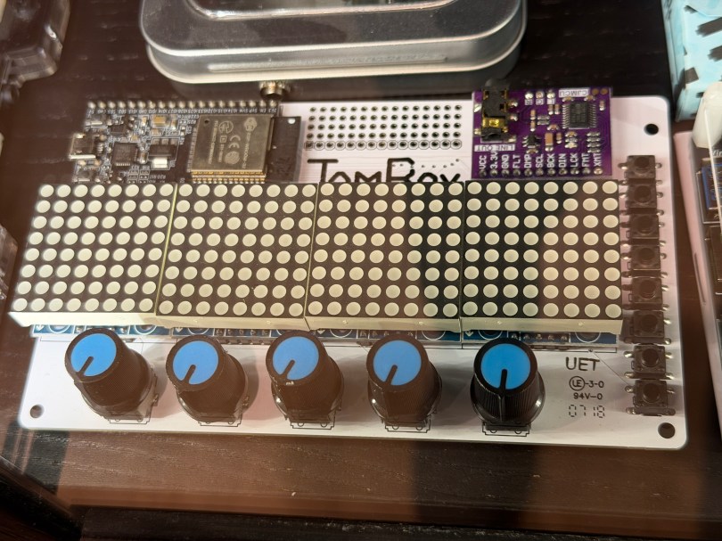
Not long ago the old JamBox sitting in one of my office display case’s caught my eye.
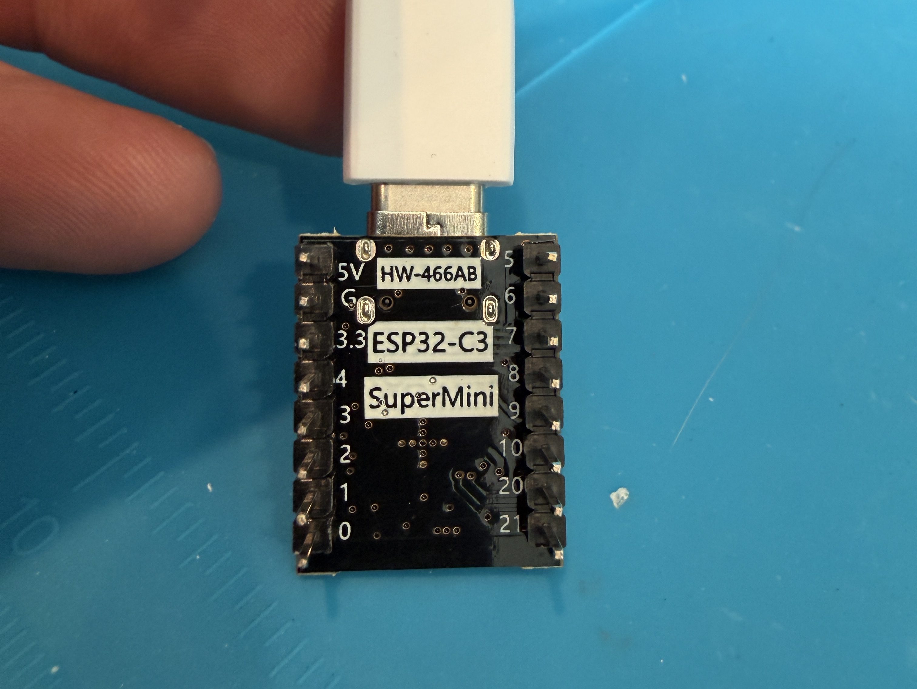
After picking it up I noticed it used an ESP32 development board, so I had to flash it for ESPHome. I downloaded the PixelOperator8 font and uploaded it to my esphome/fonts folder in Home Assistant. Then I figured out the following YAML to get the buttons, potentiometers (knobs), and LED Matrix working.
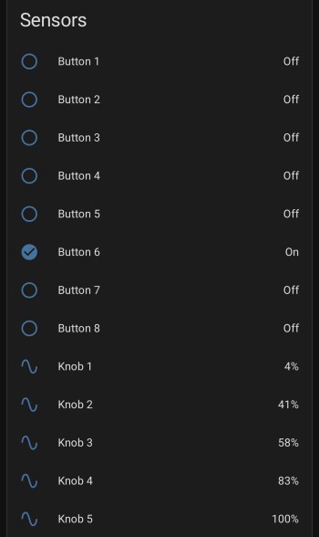
After installing the YAML and installing the device to Home Assistant, here are the sensors in the device UI.
Screenshot
The device has a ton of inputs with the eight buttons and five knobs and the 8×32 LED Matrix can display text or maybe a simple graph. I haven’t thought of a good use for it though. Do you have any ideas?
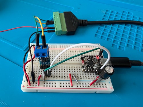
ESP32 G -> CAN Board G -> RJ45 Pin 8 -> Capacitor stripe side
ESP32 3.3 -> CAN Board 3.3 -> Capacitor non-stripe side
ESP32 Pin 4 -> CAN Board TX
ESP32 Pin 5 -> CAN Board RX
CAN Board CANH -> RJ45 Pin 5
CAN Board CANL -> RJ45 Pin 4
Start with this YAML for your ESPHome device:
# Add your standard esphome, ota, api, and wifi sections here at the top

logger:
  level: DEBUG

esp32:
  board: esp32-c3-devkitm-1
  framework:
    type: esp-idf

canbus:
  - platform: esp32_can
    id: can
    tx_pin: GPIO4
    rx_pin: GPIO5
    bit_rate: 125KBPS
    can_id: 0x05
    use_extended_id: false

    on_frame:
      - can_id: 0x000
        can_id_mask: 0x000 # This catches EVERYTHING
        then:
          - lambda: |-
              std::string res = "";
              for (int i = 0; i < x.size(); i++) {
                char buf[5];
                sprintf(buf, "%02X ", x[i]);
                res += buf;
              }
              ESP_LOGD("ALORAIR_FINDER", "Received ID: 0x%03X, Data: %s", can_id, res.c_str());

# ====== Periodic Polling to Request Status ======
interval:
  - interval: 10s
    then:
      - canbus.send:
          can_id: 0x123
          use_extended_id: false
          data: [0x00, 0x00, 0x00, 0x00, 0x00, 0x00, 0x00, 0x00]
This will test sending and receiving. After you flash the device and have it connected to the dehumidifier, open the ESPHome device log and look for lines like below.
If you see errors after the send or don’t receive messages back, try changing the bit_rate from 125 to 50, install, and recheck the logs.
If you do receive messages back, make note of the value after Received ID, which is 0x123 above. Then open up the ESPHome device’s YAML again and replace everything below type: esp-idf with the following.
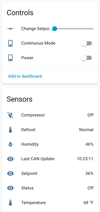
If your ID was different than 0x123 (0x3b0 seems common), change the can_id under on_frame. Update mobile_app_YOUR_PHONE for your phone. Install this new code to the device. Go to Settings -> Devices & services -> ESPHome. If your device isn’t already listed, add it, and click through to see the entities. Hopefully you see the Controls and Sensors with data.
Try to toggle the power and change the setpoint. If it’s working, the dehumidifier should respond. Good luck! If all is working, I suggest adjusting your logging level to WARN. There is some stuff in the YAML to alert if the unit sends data that isn’t recognized, because there might be flags or statuses not implemented.
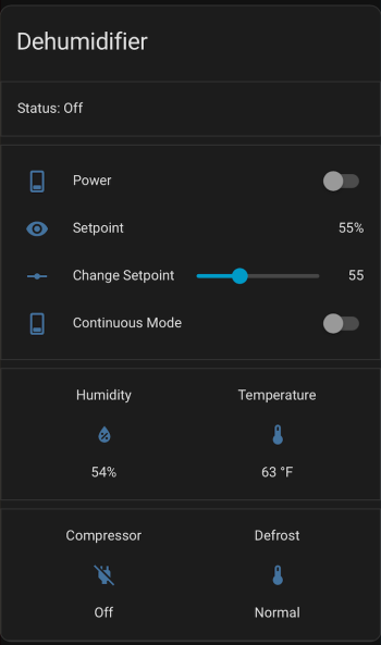
If you install the stack-in-card via HACS, here’s some YAML for your dashboard. Make sure to update the entity names to match what you have.
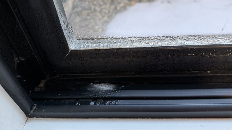
The first winter in our house was a challenge figuring out where to set the house humidifier connected to our furnace. How do you balance comfortable humidity against the risk of window condensation? I really had no idea and it was common to see water or ice on the inside of our windows during the coldest days.
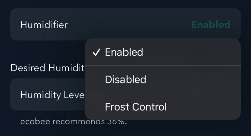
I had wired our house humidifier through the furnace so I could use the Ecobee thermostat to control it. The Ecobee has a setting called “Front Control,” but it does a poor job balancing for comfort.
Screenshot
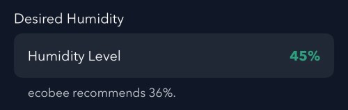
Remember this recommended humidity level for later.
Screenshot
Going from 36% to 45% is a large difference. From my testing, the humidity reported by Ecobee is 4-5 percentage points too high, which is also part of the problem and makes the air even drier. I wanted to do better and let Home Assistant handle everything.
Since we don’t use the humidifier all year, the first step was to create a Toggle (or Input Boolean) helper. I’ll manually change this when I enable/disable the humidifier in the Ecobee settings.
I installed the Thermal Comfort integration to calculate the indoor dew point and the OpenWeatherMap integration with their One Call API 3.0 for fetching weather forecasts. I use a trigger template in templates.yaml to store the forecast every hour and whenever Home Assistant starts.
The forecast is important because I don’t want to set the humidity too high and not have enough time for the house to dry out when a cold front moves in. I added another trigger template in templates.yaml, which grabs the low temperature over the next 12 hours, estimates window glass temperature, calculates an ideal indoor humidity, and determines an offset between the trusted and Ecobee humidity values. It does all of this every 15 minutes, when Home Assistant starts, and whenever there is a change to various temperature or humidity values.
With this data calculated and saved, an automation takes care of updating the humidity setpoint on the Ecobee thermostat. Whenever I have the Humidifier Enabled toggle on, it’ll update the setpoint every 30 minutes and whenever the Calculated Ideal Humidity changes.
alias: Set Thermostat Humidity
triggers:
  - entity_id: sensor.calculated_ideal_humidity
    trigger: state
  - minutes: /30
    trigger: time_pattern
conditions:
  - condition: and
    conditions:
      - condition: state
        entity_id: input_boolean.humidifier_enabled
        state:
          - "on"
      - condition: template
        value_template: >-
          {{ state_attr('sensor.calculated_ideal_humidity',
          'ecobee_compensated_target') is not none }}
        alias: Ecobee Compensated Target is not None
actions:
  - target:
      entity_id: climate.thermostat
    data:
      humidity: >-
        {{ state_attr('sensor.calculated_ideal_humidity',
        'ecobee_compensated_target') | int(35) }}
    action: climate.set_humidity
mode: restart
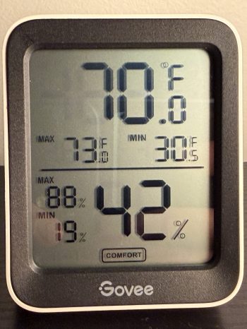
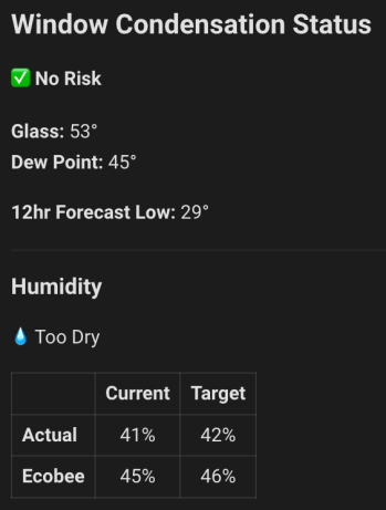
I added a card on my dashboard to see the status of everything. This was invaluable when I was testing and tweaking for several weeks.
Remember the Ecobee’s recommended 36%?! If I went by that, the actual humidity in the house at this time would have about 32%, a whole 10 percentage points dryer! Here’s the YAML for the dashboard card.
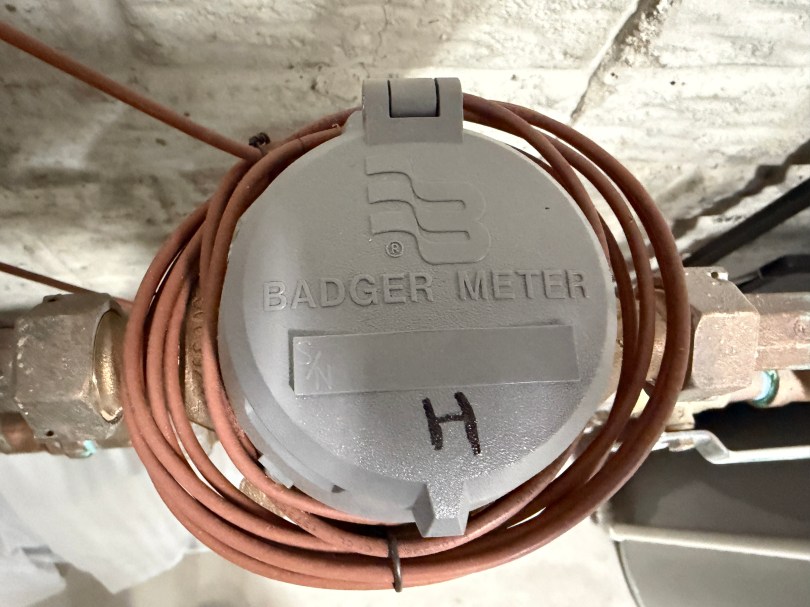
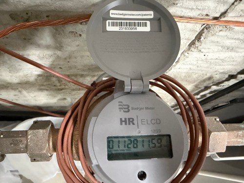
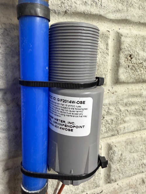
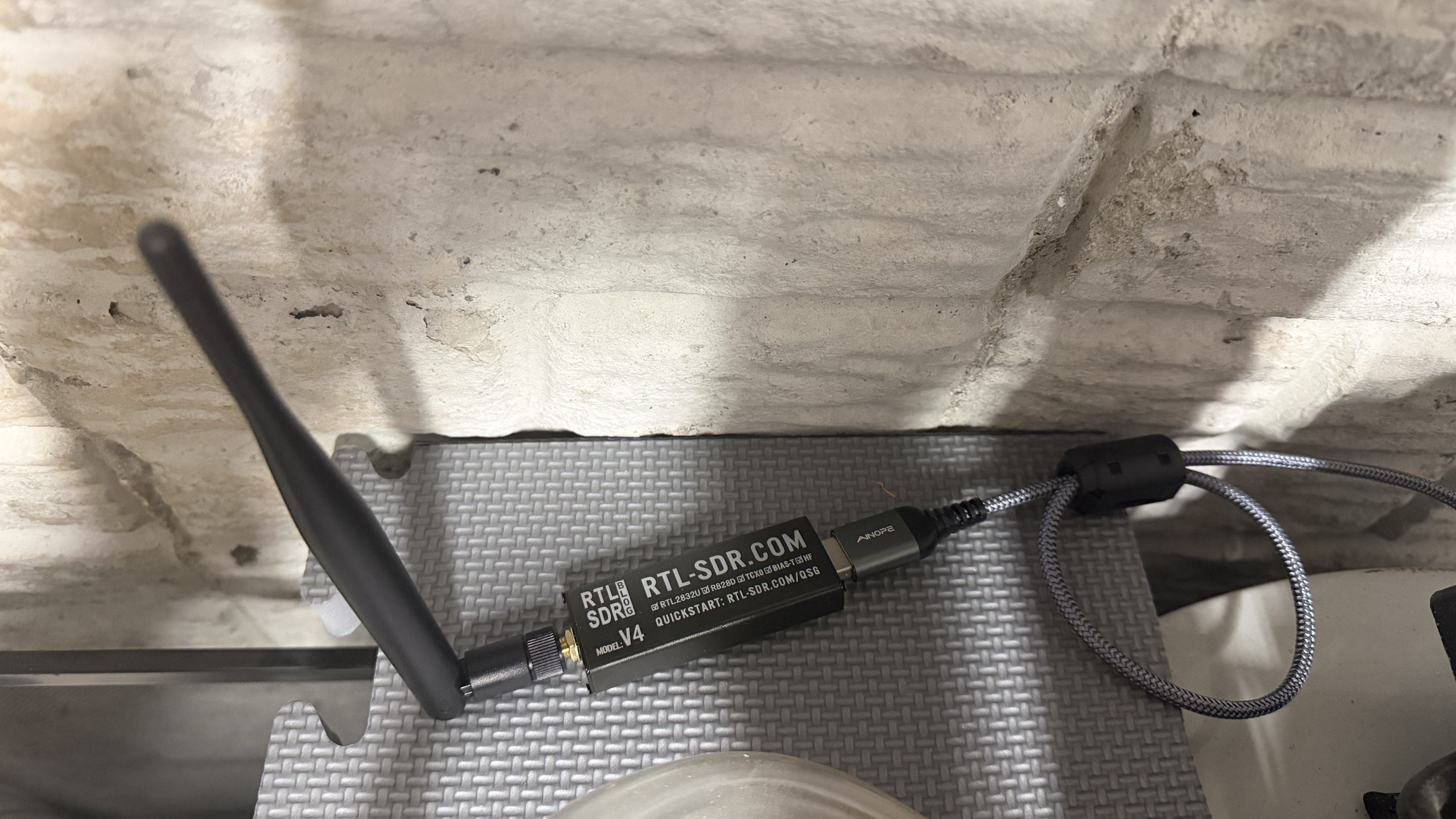
If you have Badger water meters with the Orion Endpoint GIF2014W-OSE, this post should help you read the data for use in Home Assistant. Here is what my meters look like. I have separate lines and meters for the house and outdoor, since they get charged at different rates.
The GIF2014W-OSE broadcasts data from the water meter over radio frequency (RF). Monthly or quarterly the township water department drives around neighborhoods reading these RF signals to determine everyone’s water usage. You can read the same data with a software defined radio (SDR). I’m using a RTL-SDR Blog V4 dongle with a 915MHz LoRa Antenna and ferrite beads (to filter noise) on a USB extension cable. It plugs directly in to my Home Assistant server.
If you want to test the SDR on your computer before setting everything up in Home Assistant check out the rtl_433 repo on GitHub.
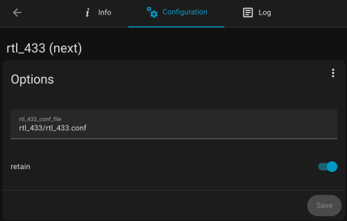
To get started in HA, make sure you’re running a MQTT broker. I use the recommended Mosquitto broker. Install the MQTT Explorer and rtl_433 (next) apps. Note, the main rtl_433 HA app wasn’t updated yet with the latest version of rtl_433, which is needed for the GIF2014W-OSE, so that’s why I had to use the (next) version. It may be updated by the time you’re reading this.
The configuration for the rtl_433 (next) app is stored in a file. I have mine at /homeassistant/rtl_433/rtl_433.conf and here is how my app configuration looks.
Below is a good start for the config file’s contents. Put in your IP address, user, and password.
sample_rate 1600k
gain 28
hop_interval 22
pulse_detect autolevel
pulse_detect minlevel=-35
report_meta level
report_meta noise
report_meta stats:1
output mqtt://[MQTT_IP],user=[MQTT_USER],pass=[MQTT_PASSWORD],retain=1

protocol 282

frequency 905.3M
frequency 906.1M
frequency 906.9M
frequency 907.7M
frequency 908.5M
frequency 909.3M
frequency 910.1M
frequency 910.9M
frequency 911.7M
frequency 912.5M
frequency 913.3M
frequency 914.1M
frequency 914.9M
frequency 915.7M
frequency 916.5M
frequency 917.3M
frequency 918.1M
frequency 918.9M
frequency 919.7M
frequency 920.5M
frequency 921.3M
frequency 922.1M
frequency 922.9M
frequency 923.7M
The water meter endpoint broadcasts across the range of 904.4 to 924.6Mhz and this is going to hop between the 24 frequencies (taken from a GitHub comment) listed in the config every 22 seconds. You may need to tweak the gain, pulse_detect, and other settings depending on your setup. Use your favorite AI to help. If you these next couple of lines to the config file you can see more of what happening, but I wouldn’t leave these in after everything is working.
verbose 7
output json
output log
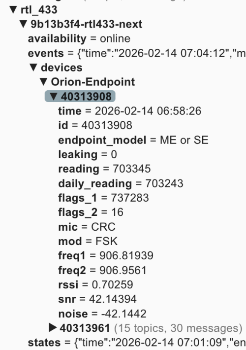
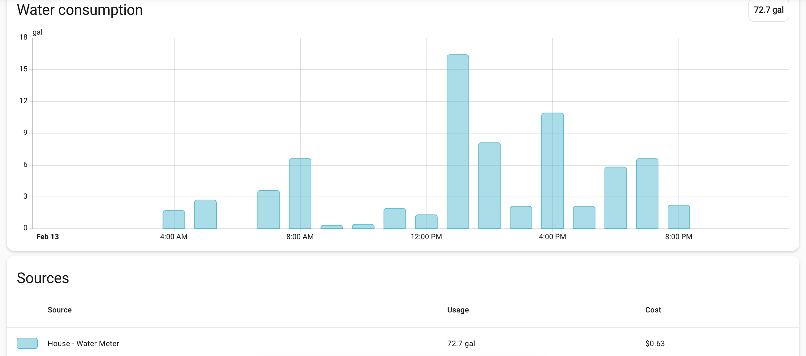
You can view the HA app’s logs to see more details. When everything is running, open up MQTT Explorer and look for the rtl_433 topics. Hopefully within an hour or two you’ll see something similar to this.
In this screenshot 40338908 and 40313961 are the ids for my meter endpoints. You may see a bunch of other ids for other meters in your neighborhood. You may have physical tags on the devices with their IDs or you can compare the reading values to what is displayed on the water meter.
Now this data can be brought in to Home Assistant. It’ll take some tinkering and customization to fit it all for your HA install. I’m also writing this over a week after setting everything up, so I don’t remember the order of adding everything, but you should be able to do most of it at once and restart. Make sure to update the name, unique_id, source, and state everywhere to fit your needs. The state_topic‘s need to match what you see in MQTT Explorer, and any other cross references have to match your renames. Only use what applies to your situation. If you only have one meter, remove all the outdoor/sprinkler stuff. I’m scraping the Saginaw Township water rates from their web site, so that stuff is going to be very custom, but gives you an idea of what you can do.
In configuration.yaml:
mqtt:
  binary_sensor:
    - name: "House Water Meter Leak"
      unique_id: "house_water_meter_leak"
      state_topic: "rtl_433/9b13b3f4-rtl433-next/devices/Orion-Endpoint/40313908/leaking"
      payload_on: "1"
      payload_off: "0"
      device_class: moisture
    - name: "Outdoor Water Meter Leak"
      unique_id: "outdoor_water_meter_leak"
      state_topic: "rtl_433/9b13b3f4-rtl433-next/devices/Orion-Endpoint/40313961/leaking"
      payload_on: "1"
      payload_off: "0"
      device_class: moisture
  sensor:
    - name: "House - Water Meter"
      unique_id: "house_water_meter"
      state_topic: "rtl_433/9b13b3f4-rtl433-next/devices/Orion-Endpoint/40313908/reading"
      unit_of_measurement: "gal"
      device_class: water
      state_class: total_increasing
      icon: mdi:water-pump
      value_template: "{{ value | float(0) / 10 }}"
    - name: "House - Water Meter Daily Snap"
      unique_id: "house_water_meter_daily_snap"
      state_topic: "rtl_433/9b13b3f4-rtl433-next/devices/Orion-Endpoint/40313908/daily_reading"
      device_class: water
      state_class: total
      unit_of_measurement: "gal"
      entity_category: diagnostic
      icon: mdi:history
      value_template: "{{ value | float(0) / 10 }}"
    - name: "House - Water Meter - Freq 1"
      unique_id: "house_water_meter_freq1"
      state_topic: "rtl_433/9b13b3f4-rtl433-next/devices/Orion-Endpoint/40313908/freq1"
      value_template: "{{ value | float(0) }}"
      unit_of_measurement: "MHz"
      state_class: measurement
      device_class: frequency
    - name: "House - Water Meter - Freq 2"
      unique_id: "house_water_meter_freq2"
      state_topic: "rtl_433/9b13b3f4-rtl433-next/devices/Orion-Endpoint/40313908/freq2"
      value_template: "{{ value | float(0) }}"
      unit_of_measurement: "MHz"
      state_class: measurement
      device_class: frequency
    - name: "Outdoor - Water Meter"
      unique_id: "water_meter_outdoor"
      state_topic: "rtl_433/9b13b3f4-rtl433-next/devices/Orion-Endpoint/40313961/reading"
      unit_of_measurement: "gal"
      device_class: water
      state_class: total_increasing
      icon: mdi:water-pump
      value_template: "{{ value | float(0) / 10 }}"
    - name: "Outdoor - Water Meter Daily Snap"
      unique_id: "outdoor_water_meter_daily_snap"
      state_topic: "rtl_433/9b13b3f4-rtl433-next/devices/Orion-Endpoint/40313961/daily_reading"
      device_class: water
      state_class: total
      unit_of_measurement: "gal"
      entity_category: diagnostic
      icon: mdi:history
      value_template: "{{ value | float(0) / 10 }}"
    - name: "Outdoor - Water Meter - Freq 1"
      unique_id: "outdoor_water_meter_freq1"
      state_topic: "rtl_433/9b13b3f4-rtl433-next/devices/Orion-Endpoint/40313961/freq1"
      value_template: "{{ value | float(0) }}"
      unit_of_measurement: "MHz"
      state_class: measurement
      device_class: frequency
    - name: "Outdoor - Water Meter - Freq 2"
      unique_id: "outdoor_water_meter_freq2"
      state_topic: "rtl_433/9b13b3f4-rtl433-next/devices/Orion-Endpoint/40313961/freq2"
      value_template: "{{ value | float(0) }}"
      unit_of_measurement: "MHz"
      state_class: measurement
      device_class: frequency

scrape:
  - resource: https://saginawtownship.org/departments/public_services/water_distribution.php
    scan_interval: 86400
    sensor:
      - name: "Saginaw House Water Rate Raw"
        select: "article ul li"
        index: 2
        value_template: >
          {{ value | regex_findall_index('Combined:\s*\$?\s*(\d+\.\d+)', ignorecase=True) }}
      - name: "Saginaw Outdoor Water Rate Raw"
        select: "article ul li"
        index: 2
        value_template: >
          {{ value | regex_findall_index('\(Sprinkler Meter\)\s*\$?\s*(\d+\.\d+)', ignorecase=True) }}
In templates.yaml:
- binary_sensor:
  - name: "Outdoor Water Flowing Hourly"
    unique_id: outdoor_water_flowing_hourly
    device_class: moving
    state: >
      {{ states('sensor.outdoor_water_hourly_change') | float(0) > 0 }}
  - name: "House Water Flowing Hourly"
    unique_id: house_water_flowing_hourly
    device_class: moving
    state: >
      {{ states('sensor.house_water_hourly_change') | float(0) > 0 }}
  - name: "Sprinklers Watering"
    unique_id: sprinklers_watering
    device_class: running
    state: >
      {{ is_state('binary_sensor.sprinkler_zone_1_watering', 'on')
         or is_state('binary_sensor.sprinkler_zone_2_watering', 'on')
         or is_state('binary_sensor.sprinkler_zone_3_watering', 'on')
         or is_state('binary_sensor.sprinkler_zone_4_watering', 'on')
         or is_state('binary_sensor.sprinkler_zone_5_watering', 'on')
         or is_state('binary_sensor.sprinkler_zone_6_watering', 'on') }}
  - name: "Outdoor Water Leak Persistent"
    unique_id: outdoor_water_leak_persistent
    device_class: problem
    delay_on: "02:00:00"
    state: >
      {% set water_usage = states('sensor.outdoor_water_hourly_change') | float(0) > 0 %}
      {% set sprinklers_active = states('sensor.sprinklers_active_last_hour') | float(0) > 0 %}

      {{ water_usage and not sprinklers_active }}
  - name: "House Water Nightly Leak Possible"
    unique_id: house_water_nightly_leak_possible
    device_class: problem
    state: >

      {% if now().hour == 6 and now().minute == 0 %}
        {# If water usage increased 7/9 hours from 9p-6a #}
        {# (allowing for minor signal lag and missed reads) #}
        {{ states('sensor.house_water_flowing_9_hours') | float(0) > 6.8 }}
      {% else %}
        {{ states('binary_sensor.house_water_nightly_leak_possible') }}
      {% endif %}
In automations.yaml:
- id: '1770044944973'
  alias: Notify - Water Meter Leak Detected
  description: ''
  triggers:
  - trigger: state
    entity_id:
    - binary_sensor.house_water_meter_leak
    - binary_sensor.outdoor_water_meter_leak
    from:
    - 'off'
    to:
    - 'on'
  actions:
  - action: notify.mobile_app_nickphone
    metadata: {}
    data:
      title: "\U0001F6B0 Water Leak Flag Detected!"
      message: The internal leak flag for {{ trigger.to_state.name }} has been triggered.            This
        usually indicates continuous flow for the last 24 hours.
      data:
        priority: high
        ttl: 0
- id: '1770082584926'
  alias: Notify - Outdoor Water Leak
  description: Alerts family when unexplained water flow persists for 2 hours
  triggers:
  - entity_id: binary_sensor.outdoor_water_leak_persistent
    from: 'off'
    to: 'on'
    trigger: state
  conditions: []
  actions:
  - action: notify.mobile_app_nickphone
    metadata: {}
    data:
      data:
        priority: high
        ttl: 0
        tag: outdoor-leak-alert
        color: '#ff0000'
      title: "\U0001F6B0 Outdoor Water Leak Detected"
      message: 'Unexplained water flow has been detected for over 2 hours. Current
        hourly rate: {{ states(''sensor.outdoor_water_hourly_change'') }} gal.'
- id: '1770084282355'
  alias: Notify - House Water Leak Possible
  description: Water meter usage increased every hour from 9p-6a
  triggers:
  - at: 07:01:00
    trigger: time
  conditions:
  - condition: state
    entity_id: binary_sensor.house_water_nightly_leak_possible
    state: 'on'
  actions:
  - data:
      title: "\U0001F3E0 House Water Alert"
      message: Potential water leak detected! Water usage increased every hour from
        9 PM to 6 AM.
      data:
        priority: high
        ttl: 0
        tag: house-leak-alert
        color: '#ffa500'
    action: notify.mobile_app_nickphone
- id: '1770485349188'
  alias: Count House Water Meter Frequency Updates
  triggers:
  - entity_id: sensor.house_water_meter_freq_1
    trigger: state
  actions:
  - target:
      entity_id: input_number.house_water_meter_freq1_updates_per_hour
    data:
      value: '{{ states(''input_number.house_water_meter_freq1_updates_per_hour'')
        | float(0) + 1 }}'
    action: input_number.set_value
- id: '1770485394121'
  alias: Count Outdoor Water Meter Frequency Updates
  triggers:
  - entity_id: sensor.outdoor_water_meter_freq_1
    trigger: state
  actions:
  - target:
      entity_id: input_number.outdoor_water_meter_freq1_updates_per_hour
    data:
      value: '{{ states(''input_number.outdoor_water_meter_freq1_updates_per_hour'')
        | float(0) + 1 }}'
    action: input_number.set_value
- id: '1770485452657'
  alias: Set - Reset Water Meter Freq Hourly
  description: ''
  triggers:
  - hours: /1
    trigger: time_pattern
    id: scheduled
  - trigger: homeassistant
    event: start
    id: restart
  conditions:
  - condition: or
    conditions:
    - condition: trigger
      id: scheduled
    - condition: template
      value_template: "{{ now().minute < 5 and (last_triggered is none or last_triggered < now().replace(minute=0, second=0, microsecond=0)) }}"
  actions:
  - action: input_number.set_value
    metadata: {}
    target:
      entity_id:
      - input_number.house_water_meter_freq1_updates_per_hour
      - input_number.outdoor_water_meter_freq1_updates_per_hour
    data:
      value: 0
- id: '1770038217308'
  alias: Notify - Saginaw Water Rate Changed
  description: ''
  triggers:
  - entity_id:
    - sensor.saginaw_house_water_rate
    - sensor.saginaw_outdoor_water_rate
    id: rate_changed
    trigger: state
    alias: Saginaw Water Rate Changes
  - entity_id:
    - sensor.saginaw_house_water_rate_raw
    - sensor.saginaw_outdoor_water_rate_raw
    to: unavailable
    for:
      seconds: 30
    id: scrape_failed
    trigger: state
    alias: Saginaw Water Rate Raw Scrape Changes
  actions:
  - choose:
    - conditions:
      - condition: trigger
        id: rate_changed
      - condition: template
        value_template: "{{ trigger.from_state.state not in ['unknown', 'unavailable']
          and \n  trigger.to_state.state not in ['unknown', 'unavailable'] }}\n"
      sequence:
      - data:
          title: "\U0001F4B0 Water Rate Change"
          message: 'Rate for {{ trigger.to_state.name }} has changed! Old Value: ${{
            trigger.from_state.state }} New Value: ${{ trigger.to_state.state }}'
          data:
            priority: high
            ttl: 0
        action: notify.mobile_app_nickphone
    - conditions:
      - condition: trigger
        id: scrape_failed
      sequence:
      - data:
          title: '⚠️ Scrape Error: Saginaw Water'
          message: 'The scrape for {{ trigger.to_state.name }} failed or returned
            non-numeric data.  Stable value of ${{ states(trigger.entity_id.replace(''_raw'',
            '''')) }} is being maintained. Check: https://saginawtownship.org/departments/public_services/water_distribution.php'
          data:
            priority: high
            ttl: 0
        action: notify.mobile_app_nickphone
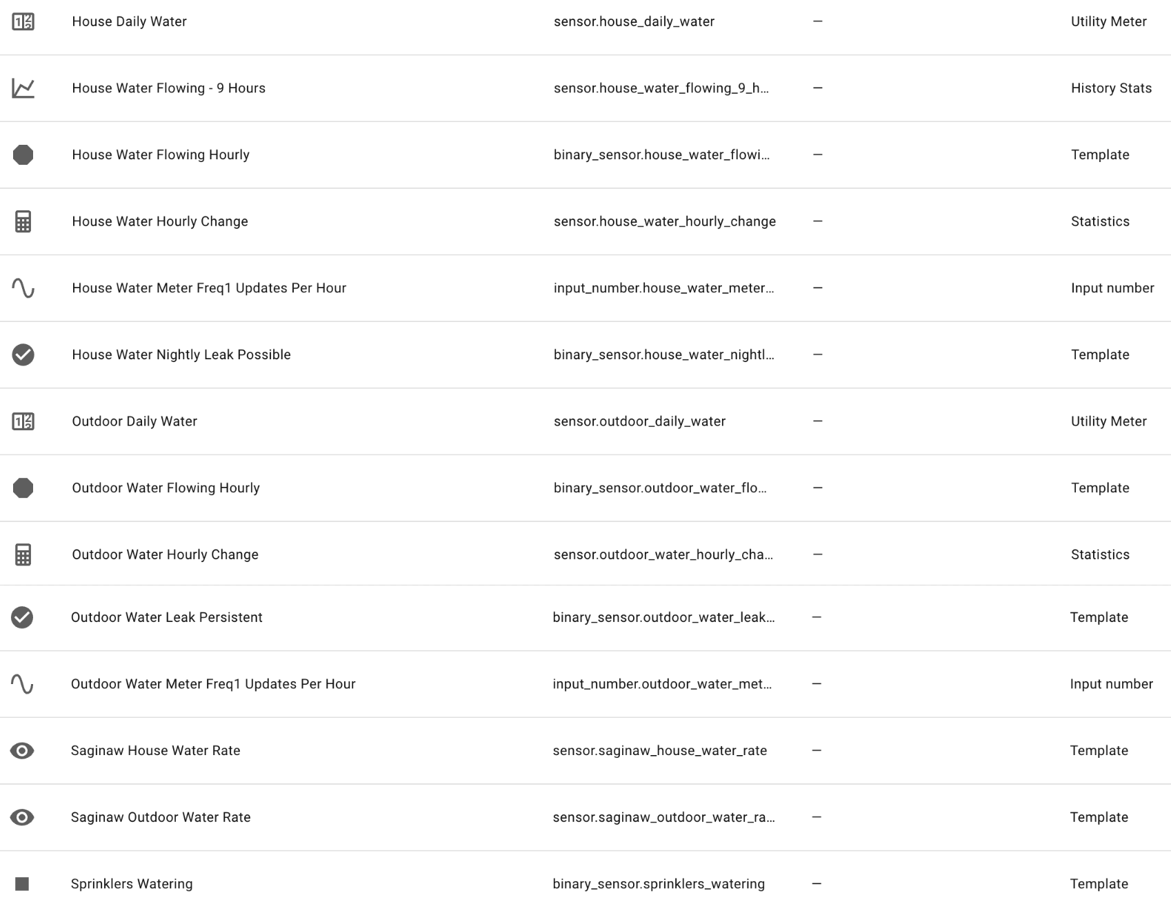
In Devices -> Helpers there are a bunch, but some come from templates above and others when you add the water data to your Energy dashboard (after a reboot and data starts coming in). Here’s my list of helpers:
Some key findings when I started looking at the data. My meters are broadcasting many times per minute, but the gallons used reading only changes at 11 minutes after every hour. They do this to save the endpoint battery I guess. So no realtime data, but hourly is better than nothing.
In the data, there is a leaking flag. From what I’ve read this flag only gets turned on if the usage increases for 24 hours straight. Not great for leak detection, but would have been useful last summer when something busted on a sprinkler line and I didn’t find out for a week or so. I have leak notifications based on these flags, but my custom leak notifications should trigger sooner. If the sprinklers have been off and the outdoor usage increases two hours in a row, I’ll get an alert. If the house usage have been increasing all through the overnight I’ll get an alert in the morning.
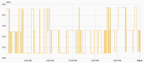
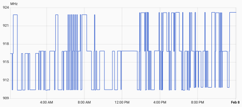
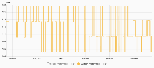
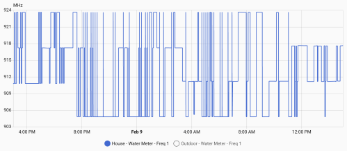
Once everything is setup, let it run. After several days, check out the freq1 sensor data, which should look similar to these graphs.
Your meters might be different, but mine hop between three frequencies at a time. There’s a low, medium, and high. Every 8 hours (3:11am, 11:11am, and 7:11pm), one of the frequencies increases by 400MHz, so over the course of a day they all increase. Then one day they all peaked and reset to the lower end of a frequency band.
From all this data I knew:
Low Band: 904.8 – 910.8 MHz with changes at 7:11 pm
Med Band: 911.2 – 917.2 MHz with changes at 3:11 am
High Band: 917.6 – 923.6 MHz with changes at 11:11 am
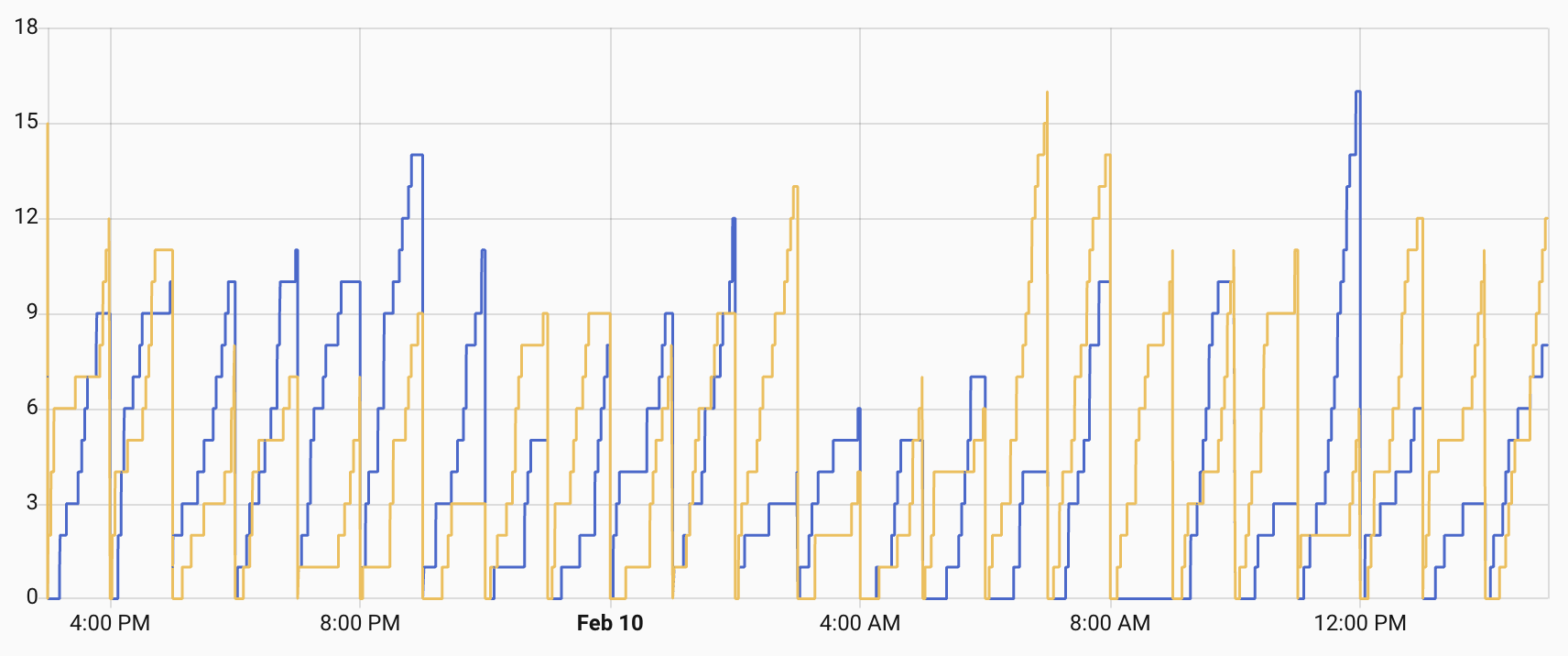
I also tracked how many times per hour I caught data from each meter.
Not bad, but some hours I’d only get one or two data packets for a meter. Technically enough, but there was a risk of missing data. Since I knew the pattern I felt I could do smarter frequency hopping with my SDR to listen for data and then capture a lot more. It worked!
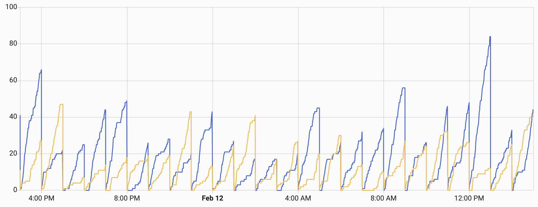
I was getting a lot more reads and rarely less than 10 in any hour. In order to do this I updated the rtl_433.conf file to replace the 24 frequencies with three bands.
The two uncommented frequencies in each band are the ones on either side of the frequency currently used by the meters. I added a scripts folder and a new update_rtl433_channels.sh file in there.
#!/bin/bash
# update_rtl433_channels.sh
#
# Advances one band's frequency pair in the rtl_433 config.
# Two adjacent frequencies are active per band (channel ± 0.1 MHz).
# Each shift: comment both active, uncomment the next two commented lines.
# At wrap (no more commented lines after active): jump to first two.
#
# Usage: update_rtl433_channels.sh <low|mid|high> [config_path]

BAND="$1"
CONFIG_PATH="${2:-/config/rtl_433/rtl_433.conf}"

if [ -z "$BAND" ]; then
    echo "Usage: $0 <low|mid|high> [config_path]"
    exit 1
fi

if [ ! -f "$CONFIG_PATH" ]; then
    echo "Error: Config file not found: $CONFIG_PATH"
    exit 1
fi

case "$BAND" in
    low)  SECTION="# Low band -" ;;
    mid)  SECTION="# Mid band -" ;;
    high) SECTION="# High band -" ;;
    *)    echo "Error: band must be low, mid, or high"; exit 1 ;;
esac

SECTION_START=$(grep -n "$SECTION" "$CONFIG_PATH" | head -1 | cut -d: -f1)
if [ -z "$SECTION_START" ]; then
    echo "Error: Could not find section '$SECTION' in config"
    exit 1
fi

NEXT_SECTION=$(tail -n +$((SECTION_START + 1)) "$CONFIG_PATH" | grep -n "^# .* band -" | head -1 | cut -d: -f1)
if [ -z "$NEXT_SECTION" ]; then
    SECTION_END=$(wc -l < "$CONFIG_PATH")
else
    SECTION_END=$((SECTION_START + NEXT_SECTION - 1))
fi

echo "Band: $BAND (lines $SECTION_START-$SECTION_END)"

# Find all active (uncommented) frequency lines
ACTIVE_ABS=()
for LINE_NUM in $(seq "$SECTION_START" "$SECTION_END"); do
    if sed -n "${LINE_NUM}p" "$CONFIG_PATH" | grep -q "^frequency "; then
        ACTIVE_ABS+=("$LINE_NUM")
    fi
done

if [ "${#ACTIVE_ABS[@]}" -ne 2 ]; then
    echo "Error: Expected 2 active frequencies, found ${#ACTIVE_ABS[@]}"
    exit 1
fi

FIRST_ABS=${ACTIVE_ABS[0]}
SECOND_ABS=${ACTIVE_ABS[1]}

echo "Active:"
echo "  Line $FIRST_ABS: $(sed -n "${FIRST_ABS}p" "$CONFIG_PATH")"
echo "  Line $SECOND_ABS: $(sed -n "${SECOND_ABS}p" "$CONFIG_PATH")"

# Find the next TWO commented frequency lines after the LAST active line
NEXT_COMMENTED=()
for LINE_NUM in $(seq $((SECOND_ABS + 1)) "$SECTION_END"); do
    if sed -n "${LINE_NUM}p" "$CONFIG_PATH" | grep -q "^#frequency "; then
        NEXT_COMMENTED+=("$LINE_NUM")
        if [ "${#NEXT_COMMENTED[@]}" -eq 2 ]; then
            break
        fi
    fi
done

if [ "${#NEXT_COMMENTED[@]}" -lt 2 ]; then
    # At end of section — wrap to first two
    echo "End of section, wrapping to first two"

    sed -i "${FIRST_ABS}s/^frequency /#frequency /" "$CONFIG_PATH"
    sed -i "${SECOND_ABS}s/^frequency /#frequency /" "$CONFIG_PATH"

    WRAP_LINES=()
    for LINE_NUM in $(seq "$SECTION_START" "$SECTION_END"); do
        if sed -n "${LINE_NUM}p" "$CONFIG_PATH" | grep -q "^#frequency "; then
            WRAP_LINES+=("$LINE_NUM")
            if [ "${#WRAP_LINES[@]}" -eq 2 ]; then
                break
            fi
        fi
    done

    sed -i "${WRAP_LINES[0]}s/^#frequency /frequency /" "$CONFIG_PATH"
    sed -i "${WRAP_LINES[1]}s/^#frequency /frequency /" "$CONFIG_PATH"
else
    echo "Advancing: commenting $FIRST_ABS,$SECOND_ABS, uncommenting ${NEXT_COMMENTED[0]},${NEXT_COMMENTED[1]}"

    sed -i "${FIRST_ABS}s/^frequency /#frequency /" "$CONFIG_PATH"
    sed -i "${SECOND_ABS}s/^frequency /#frequency /" "$CONFIG_PATH"
    sed -i "${NEXT_COMMENTED[0]}s/^#frequency /frequency /" "$CONFIG_PATH"
    sed -i "${NEXT_COMMENTED[1]}s/^#frequency /frequency /" "$CONFIG_PATH"
fi

echo ""
echo "Active frequencies:"
grep "^frequency " "$CONFIG_PATH"
This file needs a permissions change. Install the Terminal & SSH app in HA, start it, open it, and type: chmod +x /config/config/update_rtl433_channels.sh.
- id: '1770813439694'
  alias: RTL 433 - Shift Low Band Frequencies
  description: Advances low band frequencies at 00:11 UTC daily
  triggers:
  - trigger: template
    value_template: '{{ utcnow().strftime(''%H:%M'') == ''00:11'' }}'
    id: scheduled
  - trigger: homeassistant
    event: start
    id: restart
  conditions:
  - condition: or
    conditions:
    - condition: trigger
      id: scheduled
    - condition: and
      conditions:
      - condition: template
        value_template: '{% set m = utcnow().hour * 60 + utcnow().minute %} {{ 11
          <= m <= 16 }}'
      - condition: template
        value_template: '{% set lt = state_attr(''automation.rtl_433_shift_low_band_frequencies'',
          ''last_triggered'') %} {{ lt is none or lt.date() < now().date() }}'
  actions:
  - action: shell_command.rtl433_shift_low
  - delay:
      seconds: 5
  - action: hassio.addon_restart
    data:
      addon: 9b13b3f4_rtl433-next
  - action: homeassistant.update_entity
    target:
      entity_id: sensor.rtl_433_freq_hops
  mode: single
- id: '1770813477228'
  alias: RTL 433 - Shift Mid Band Frequencies
  description: Advances mid band frequencies at 08:11 UTC daily
  triggers:
  - trigger: template
    value_template: '{{ utcnow().strftime(''%H:%M'') == ''08:11'' }}'
    id: scheduled
  - trigger: homeassistant
    event: start
    id: restart
  conditions:
  - condition: or
    conditions:
    - condition: trigger
      id: scheduled
    - condition: and
      conditions:
      - condition: template
        value_template: '{% set m = utcnow().hour * 60 + utcnow().minute %} {{ 491
          <= m <= 496 }}'
      - condition: template
        value_template: '{% set lt = state_attr(''automation.rtl_433_shift_mid_band_frequencies'',
          ''last_triggered'') %} {{ lt is none or lt.date() < now().date() }}'
  actions:
  - action: shell_command.rtl433_shift_mid
  - delay:
      seconds: 5
  - action: hassio.addon_restart
    data:
      addon: 9b13b3f4_rtl433-next
  - action: homeassistant.update_entity
    target:
      entity_id: sensor.rtl_433_freq_hops
  mode: single
- id: '1770813511146'
  alias: RTL 433 - Shift High Band Frequencies
  description: Advances high band frequencies at 16:11 UTC daily
  triggers:
  - trigger: template
    value_template: '{{ utcnow().strftime(''%H:%M'') == ''16:11'' }}'
    id: scheduled
  - trigger: homeassistant
    event: start
    id: restart
  conditions:
  - condition: or
    conditions:
    - condition: trigger
      id: scheduled
    - condition: and
      conditions:
      - condition: template
        value_template: '{% set m = utcnow().hour * 60 + utcnow().minute %} {{ 971
          <= m <= 976 }}'
      - condition: template
        value_template: '{% set lt = state_attr(''automation.rtl_433_shift_high_band_frequencies'',
          ''last_triggered'') %} {{ lt is none or lt.date() < now().date() }}'
  actions:
  - action: shell_command.rtl433_shift_high
  - delay:
      seconds: 5
  - action: hassio.addon_restart
    data:
      addon: 9b13b3f4_rtl433-next
  - action: homeassistant.update_entity
    target:
      entity_id: sensor.rtl_433_freq_hops
  mode: single
Make sure to uncomment the correct frequencies in each band, update the automation trigger times, and make sure the slug for the rtl433-next app is correct. Each time an automation runs the active frequencies are updated for the associated band. Since they should be on both sides of the frequency used by the water meter both can read the RF broadcasts. When it gets to the end of the band’s frequency list, it shifts up to the top of the list. Since I need to make sure these three automations run, even if a restart happens at trigger time, there is some retry logic built in.
A lot of this is dependent on your water meters and situation, but hopefully it gives you enough information to make it work.
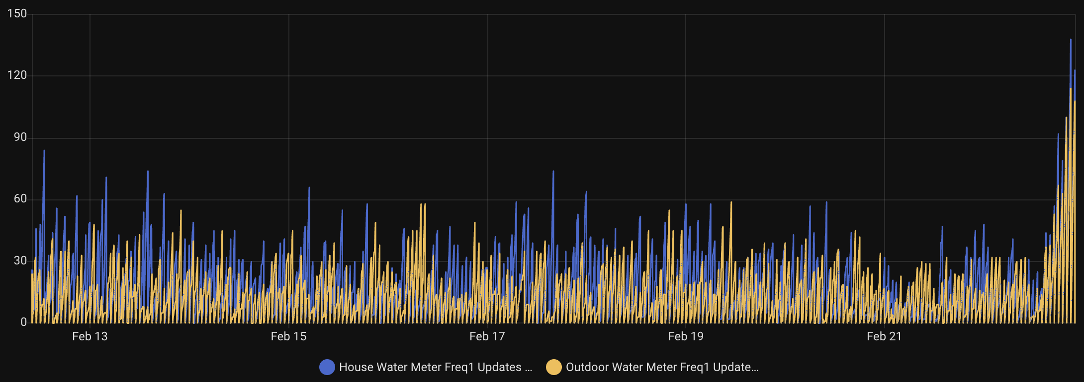
Update: After getting everything setup, I had some issues, collected more data, tested, collaborated with AI, improved the location of my SDR, and got it working much much better. The code is updated above and now I’m collecting 100 or more data points per meter during some hours. Check out the hourly data read counters and how much taller the bars at at the end of this chart!
One of our daily tasks is to clean out the cat litter boxes and we (on maybe I just wanted an excuse to automate part of the process!) run in to a couple of small problems:
We usually don’t know if the other has already cleaned them.
We obviously don’t want to forget.
Since I primarily took over this job, I’ve been using a daily reminder, but it’s on my iPhone nagging me all day, even though it’s set for noon. I only need a reminder when it doesn’t get done.
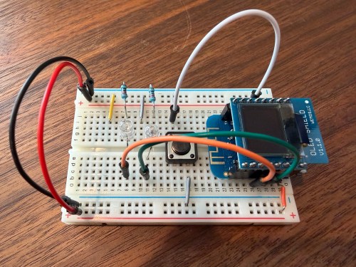
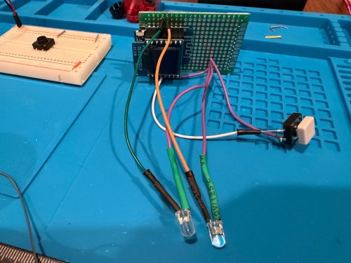
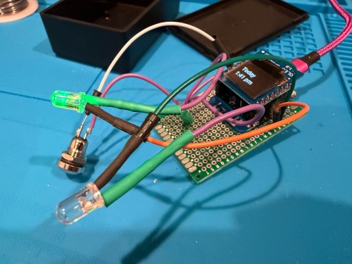
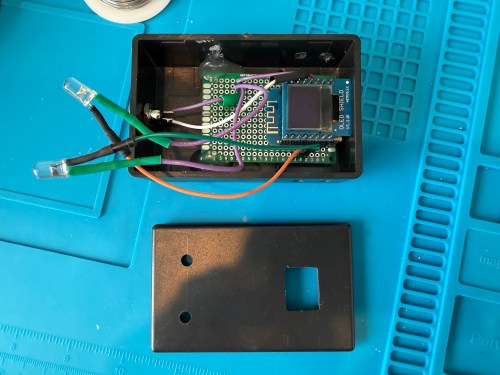
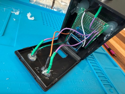
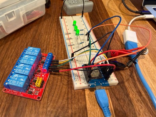
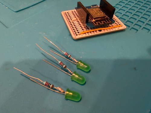
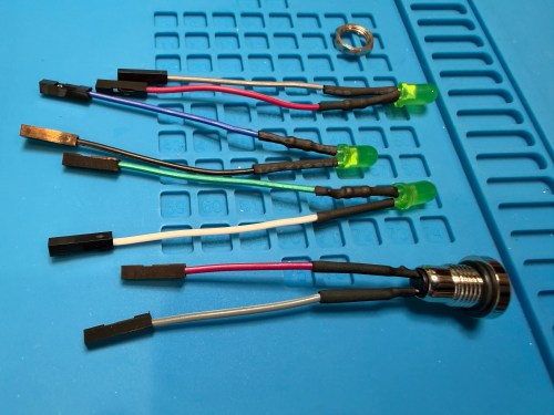
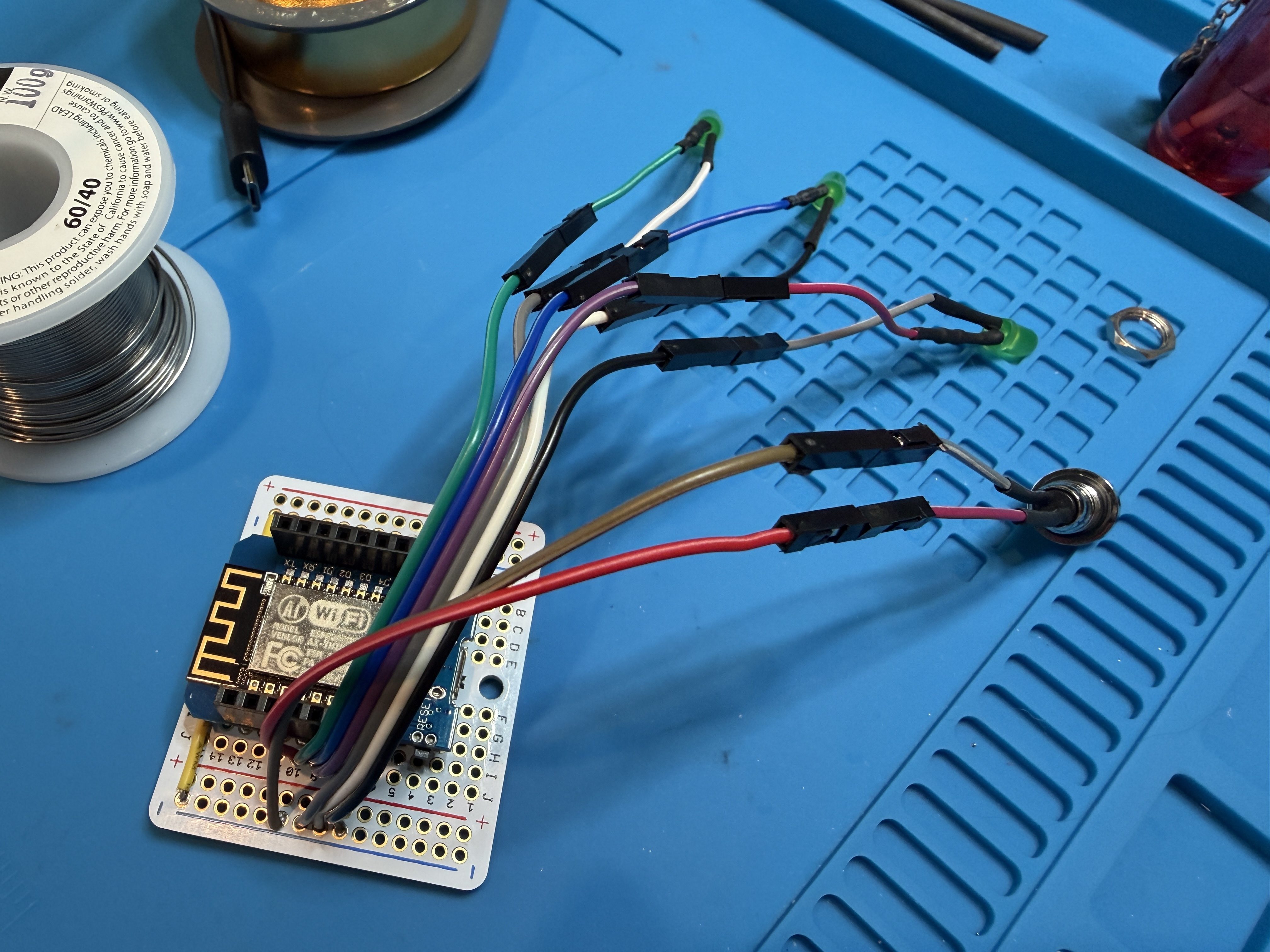
I thought of a solution with an ESPHome based device and Home Assistant. I used a WEMOS D1 Mini Lite, WEMOS OLED Shield, button, red LED, green LED, and 220 Ohm resistors. I connected everything on a breadboard for testing and then made it more permanent.
Key functionality:
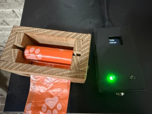
During the day, the green LED will be lit if the litter boxes have been cleaned and the red LED if they need to be cleaned. If we’re walking by, green means keep going and red means stop here.
At night (8pm to 8am), the LEDs are off, unless the device is woken up.
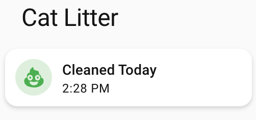
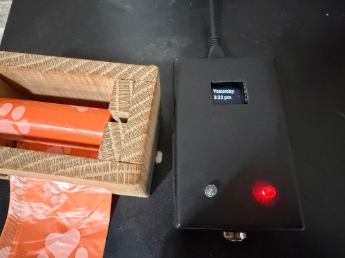
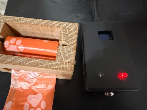
Press the button to turn on the display and status LED if at night. The display shows the last time the litter was cleaned in one of three formats, depending on how long it’s been.
Today 1:23 PM
Yesterday 2:48 PM
2 days ago 11:00 AM
Press the button when the display is on to update the litter box last cleaned date and time. The LEDs flash to signify something is happening. The new date and time gets shown on the display.
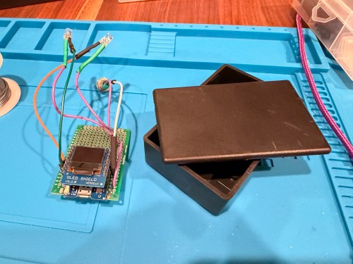
After 30 seconds the display turns off.
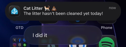
At 4pm send a reminder to our phones if the litter boxes need to be cleaned.
In Home Assistant a toggle can disable the reminders. Useful when we’re on vacation.
I also added a couple of simpler helpers via Settings -> Devices & services -> Helpers:
Cat Litter Last Cleaned – Date and time
Cat Litter Reminders – Toggle
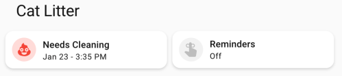
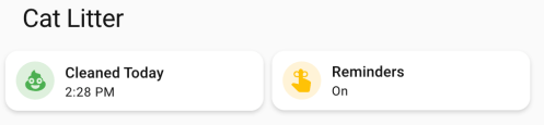
Finally, I added cards to a Home Assistant dashboard. See screenshots of the different states of each card below.
Here’s the dashboard YAML if you want it.
type: horizontal-stack
title: Cat Litter
cards:
  - type: custom:mushroom-template-card
    primary: >-
      {% set last = states('input_datetime.cat_litter_last_cleaned') |
      as_datetime %}

      {% if last is none %}
        Unknown State
      {% else %}
        {% set diff = (now().date() - last.date()).days %}
        {% if diff == 0 %}
        Cleaned Today
        {% else %}
        Needs Cleaning
        {% endif %}
      {% endif %}
    icon: mdi:emoticon-poop
    features_position: bottom
    secondary: >-
      {% set last = states('input_datetime.cat_litter_last_cleaned') |
      as_datetime %}

      {% if last is none %}

      ???

      {% else %}
        {% set diff = (now().date() - last.date()).days %}
        {% if diff > 0 %}
          {{ last.strftime('%b %-d') }} -
        {% endif %}
        {{ last.strftime('%-I:%M %p') }}
      {% endif %}
    color: |-
      {% if is_state('binary_sensor.litter_needs_cleaning', 'on') %}
        red
      {% else %}
        green
      {% endif %}
    tap_action:
      action: more-info
    icon_tap_action:
      action: perform-action
      perform_action: script.cat_litter_cleaned
      target: {}
      confirmation:
        text: Are you sure you want to update the last cleaned date/time to now?
    entity: input_datetime.cat_litter_last_cleaned
  - type: custom:mushroom-entity-card
    entity: input_boolean.cat_litter_reminders
    name: Reminders
    tap_action:
      action: toggle
    hold_action:
      action: more-info
    icon_color: amber
If we get a reminder, it looks like this. We can click I did it to update the date/time to now if we forgot to press the button on the physical device. With the automation set to run at 4pm, we should rarely see this though.
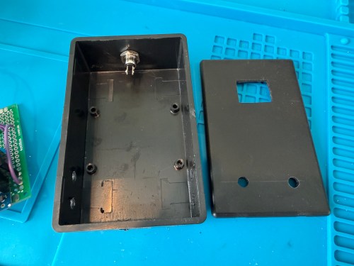
The final device lives right next to the waste bag dispenser I made. This way it’s easy to see the state and hit the button when cleaning out the litter. Here are photos in place with a few different states.
This project was so fun. Using Google Gemini for stuff like this makes it so much faster. I’ve had some of these microcontrollers and other parts for almost a decade so it’s nice to finally put them to use.
What other features or automations would you add to this? Have you built anything similar?
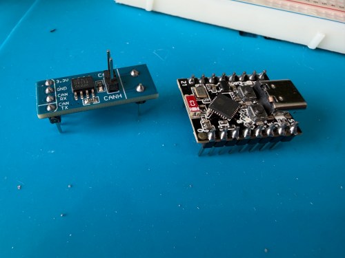
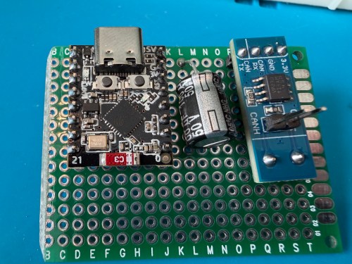
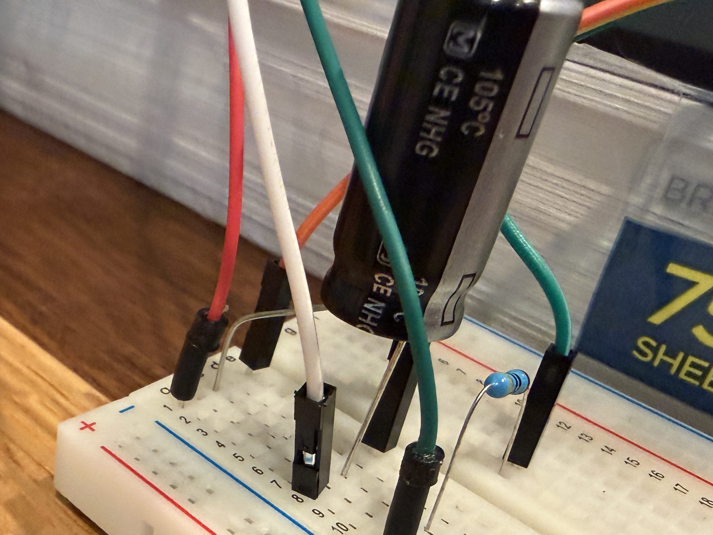
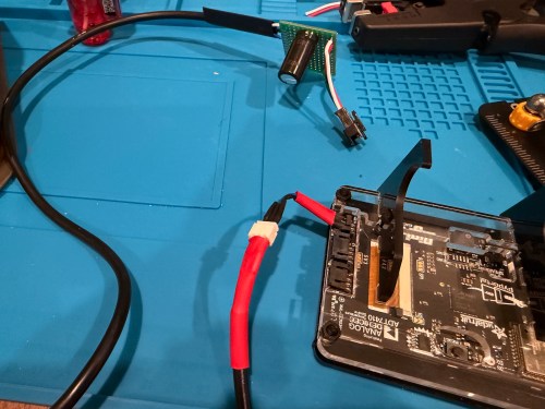
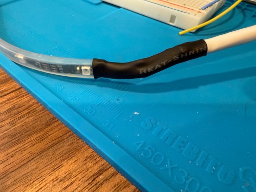
I picked up a 5m strip of adressable LEDs for my PyPortal device. The strip has 60 LEDs/m, which is double the density of the Neopixel strip I fried. To prevent future accidents, I tested improvements. Adding a 1,000 µF electrolytic capacitor protects the LEDs from a power spike and a 470Ω resister protects the first LED from data ringing.
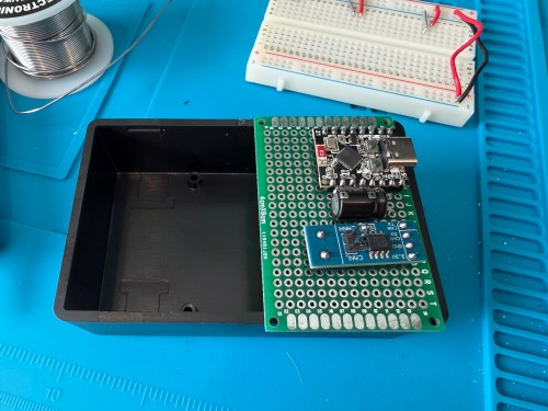
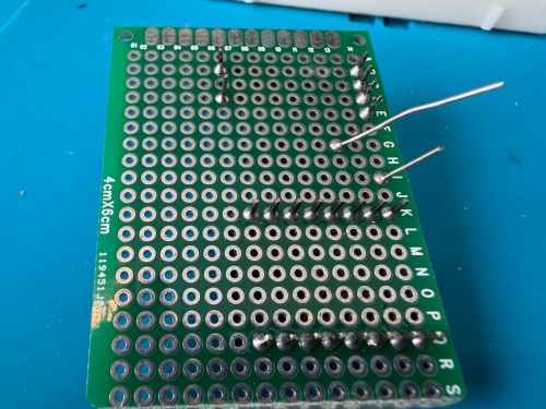
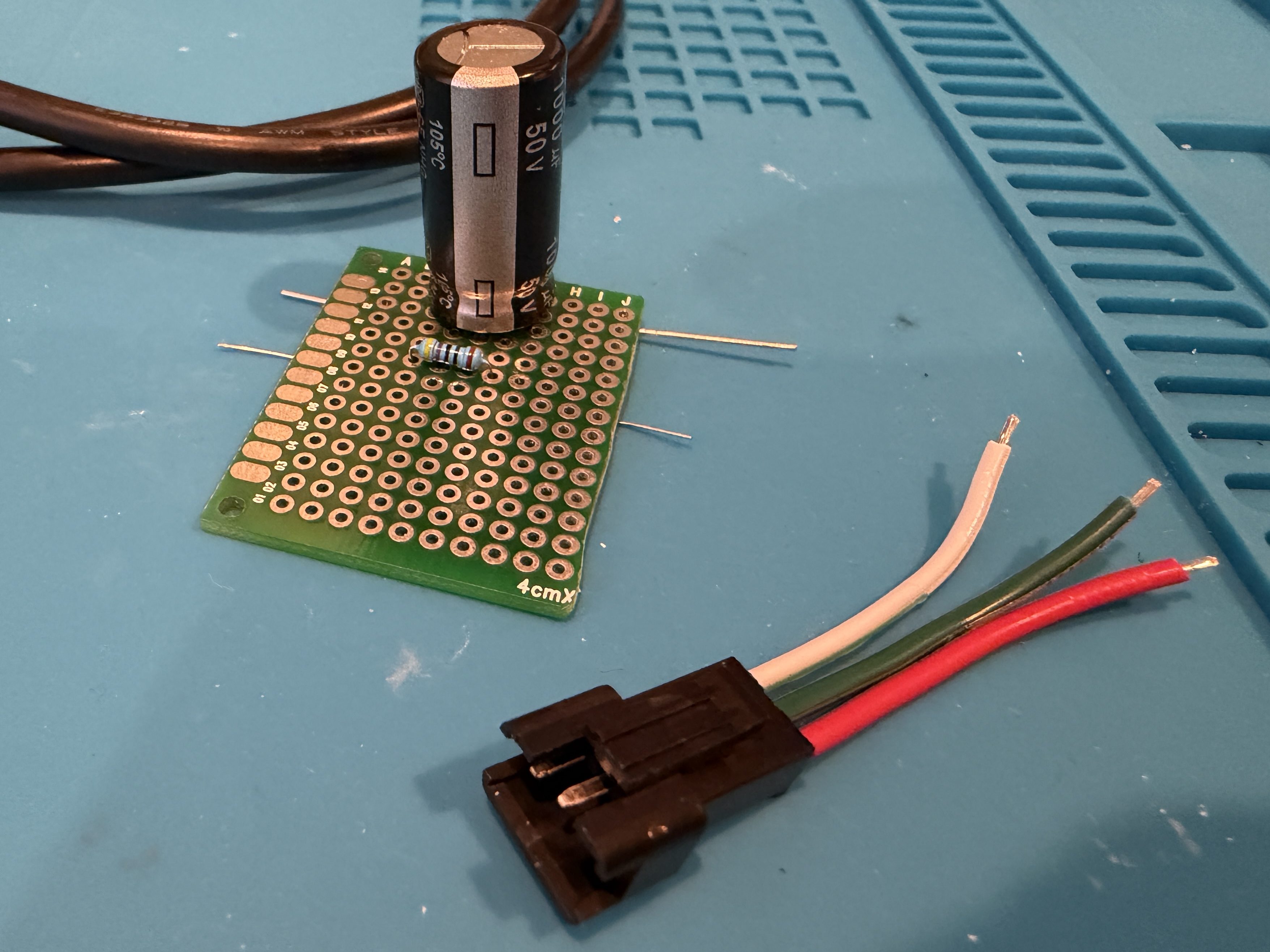
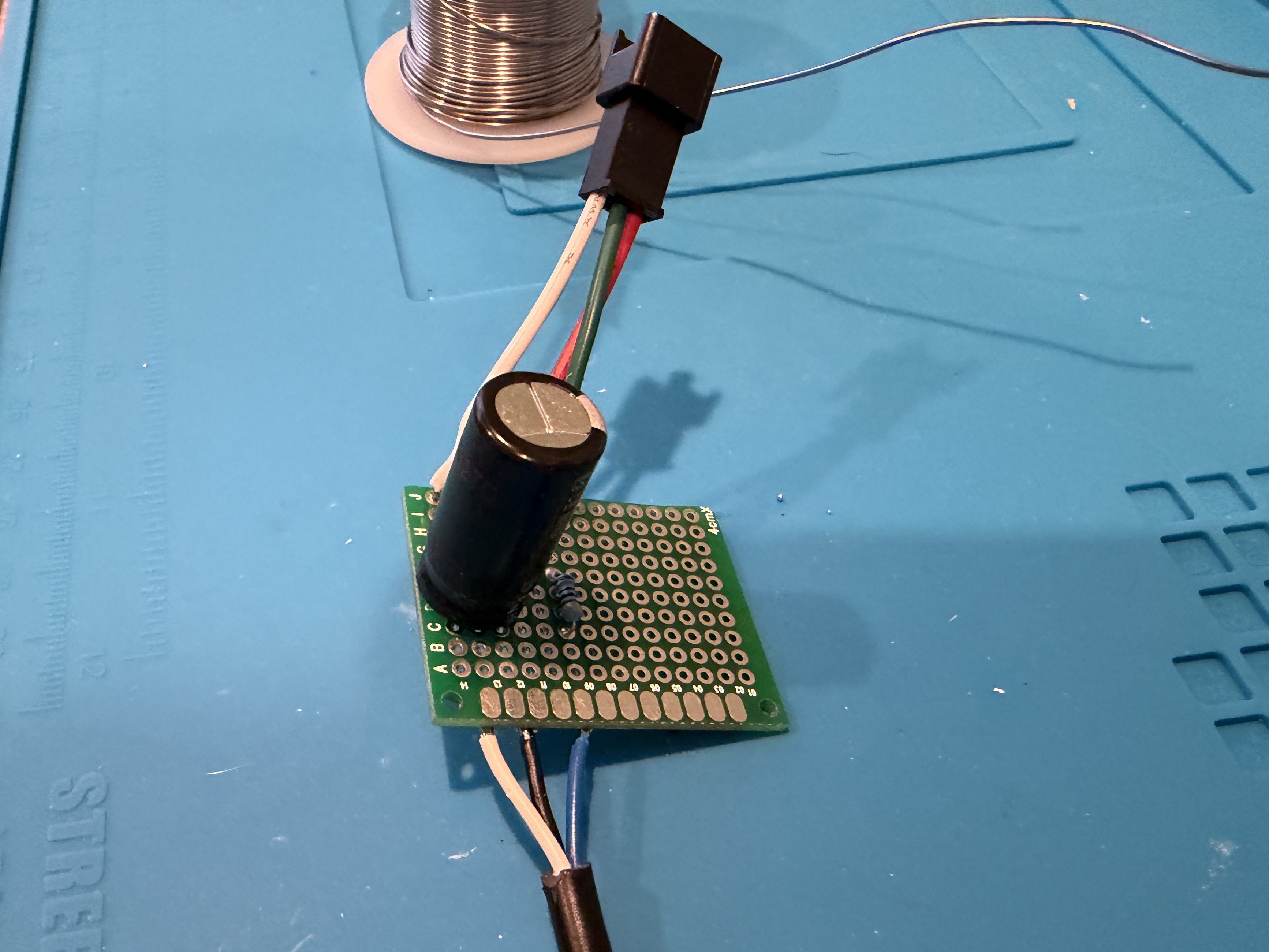
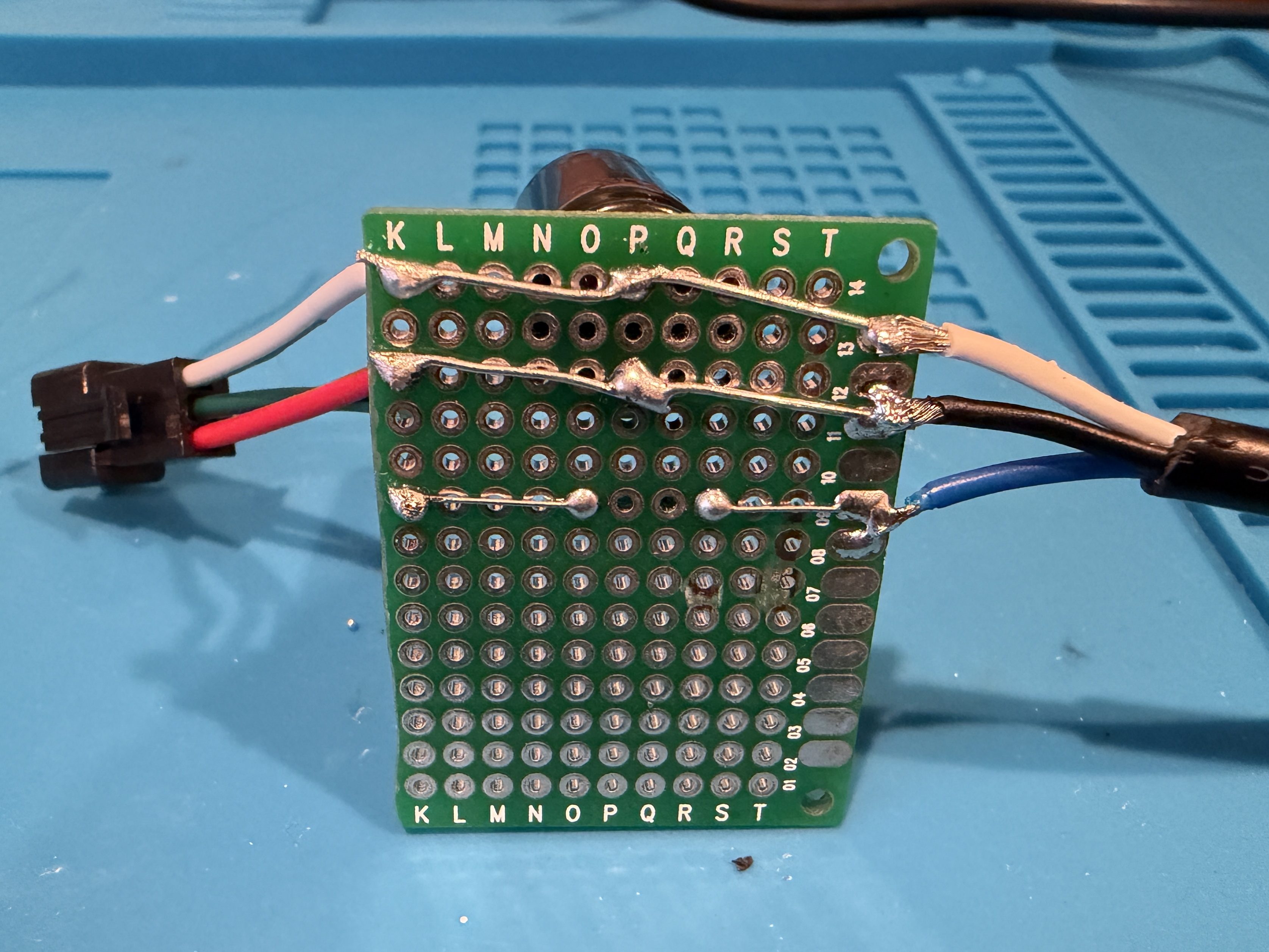
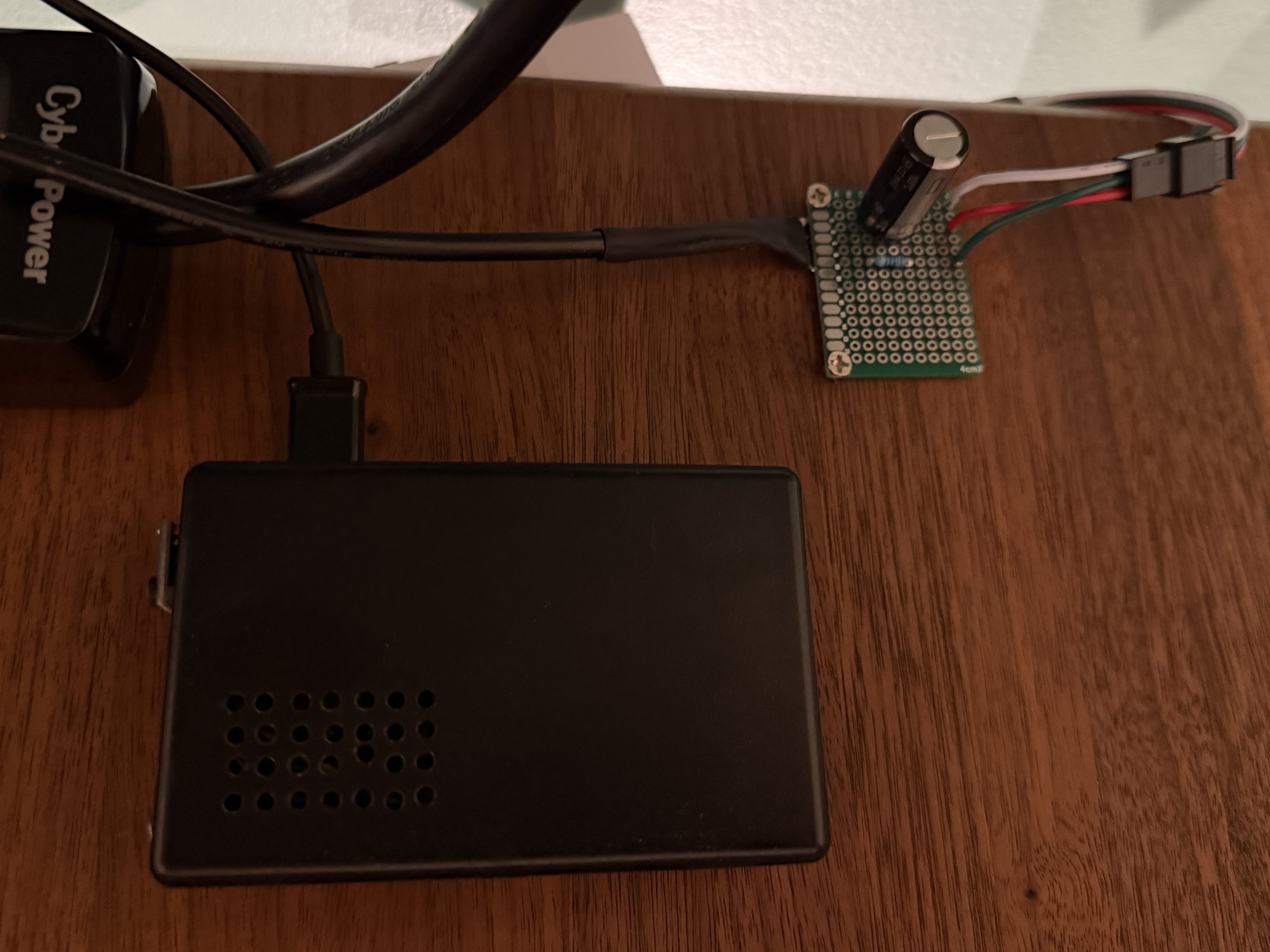
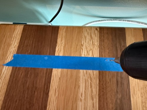
Everything worked great, so I cut off a section of 62 LEDs. Then I worked on a little board and better wiring.
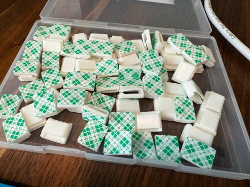
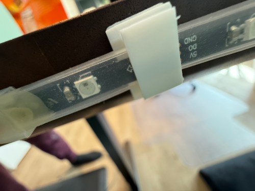
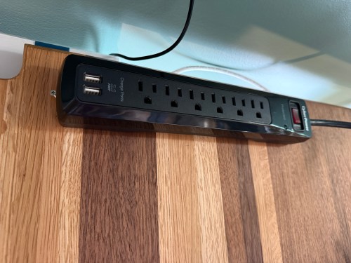
I didn’t trim the protoboard, so I could use the two holes to screw it to the undersize of my desk. This LED strip had an adhesive backing, which worked much better than the clips. I did a bit of cable management and also mounted the air quality monitor under the desk.
The code, which can be found on GitHub, got a bunch of small improvements:
Updated the LED count
Limited brightness to 50%, which is plenty and helps with power draw
Adjusted the pulse functionality to account for the brightness limit
Added a button to the interface which can be used to clear the LEDs
When filling a color, reset the LED params global, so an animation won’t play on the next loop
Tweaked the chase functionality to work better with the new LED density
Changed the button success animation so the loop continues sooner
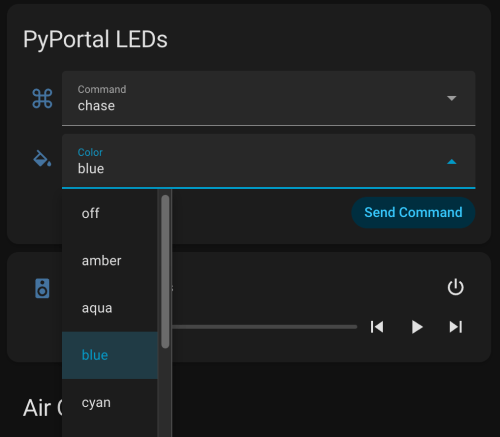
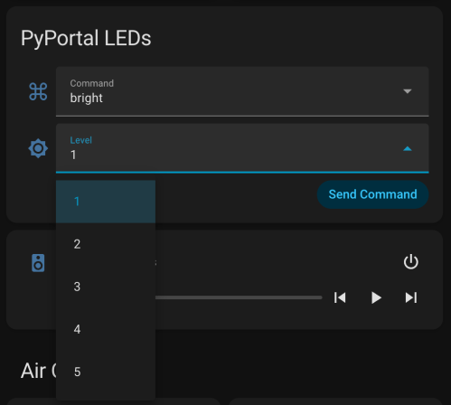
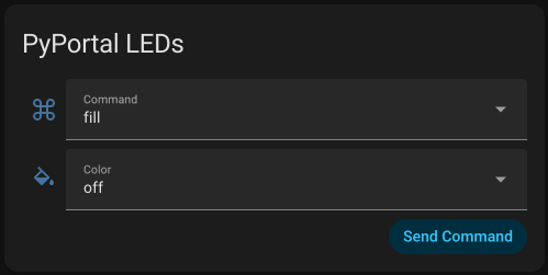
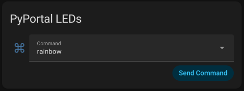
I had Google Gemini help me some stuff. First was to update the PyPortal firmware and CircuitPython version. Then update the code to make it compatible with CircuitPython 10.03. I also made an interface for my dashboard where I can select the different commands and options to send to the device manually instead of typing them in through Developer Tools -> Actions in Home Assistant.
Here’s a new demo video, so you can see how it works and what the lighting looks like.
Of course, the real power still comes from automations, where something happening around the house triggers Home Assistant to send commands to the device. Time to work on more of those. Almost a year later and this project is finally where I hoped it would end up.
I’ll likely turn this into something that interfaces with my Home Assistant server to control different devices around my house.
The PyPortal has been sitting on a shelf ever since. Way back in February, it caught my eye, and I picked it up, not remembering what it’s capabilities were. Then I started upgrading IKEA air quality monitors and even made my own. Since I’m at the desk in my office a large portion of the week I thought I would make that 2019 prediction come true.
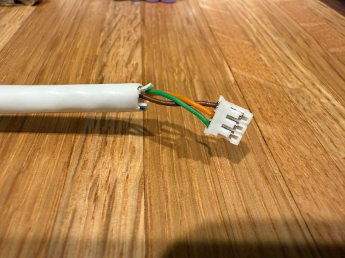
I could show a bunch of data on the screen and the PyPortal has a touchscreen, so I could display buttons for triggering things around the house. The device also has connectors for doing GPIO, so I got the idea of adding an LED strip, which I could use for notifications. I even had a meter long strip of Adafruit Mini Skinny NeoPixels I had bought in 2017 and never touched that would be perfect. I needed to buy a 2.0mm JST PH Connector kit in order to make a wire that would connect to the pack of the PyPortal. I ended up using a piece of Cat6 cable, even though I only needed 3 of the 8 wires inside.
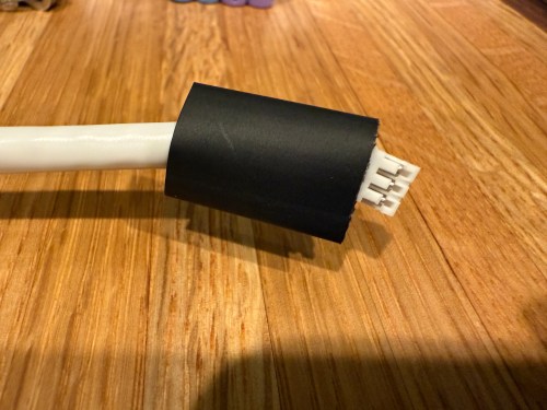
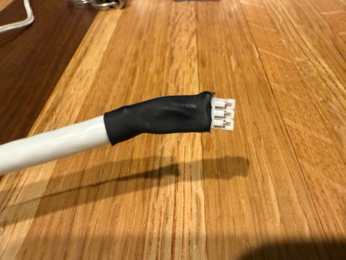
All of this was done back in March. I quickly began having issues with the ethernet cable and the small JST connectors, so I put this post on pause. Figured it was time to finally fix this before the end of the year. While testing, I determined the LED strip got fried up at some point. It was probably some kind of short from the janky wire.
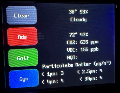
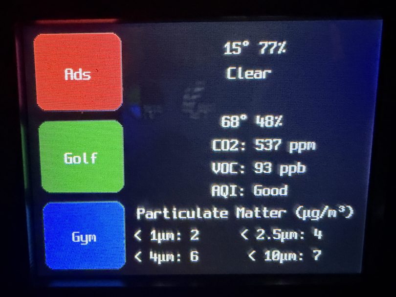
Here’s what my display looks like.
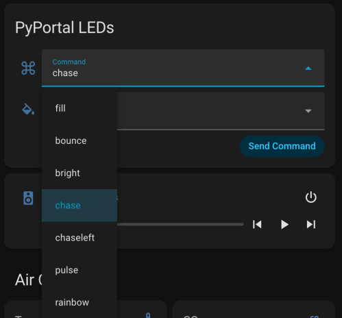
My favorite aspect of the project and code is being able to publish MQTT messages from Home Assistant, which the PyPortal listens for and reacts to. I can send various commands, such as fill:blue, which turns all of the LEDs blue, or whatever color I set. I have commands to chase a color from one side to the other, bounce a color from left to right and back to the left, pulse the entire strip, animate a rainbow, or set the brightness. Since I don’t have another strip of Neopixels, in order to create a demo video, I wired up a 24 LED circle. You’ll have to imagine the effects on the back of my desk, lighting up the wall.
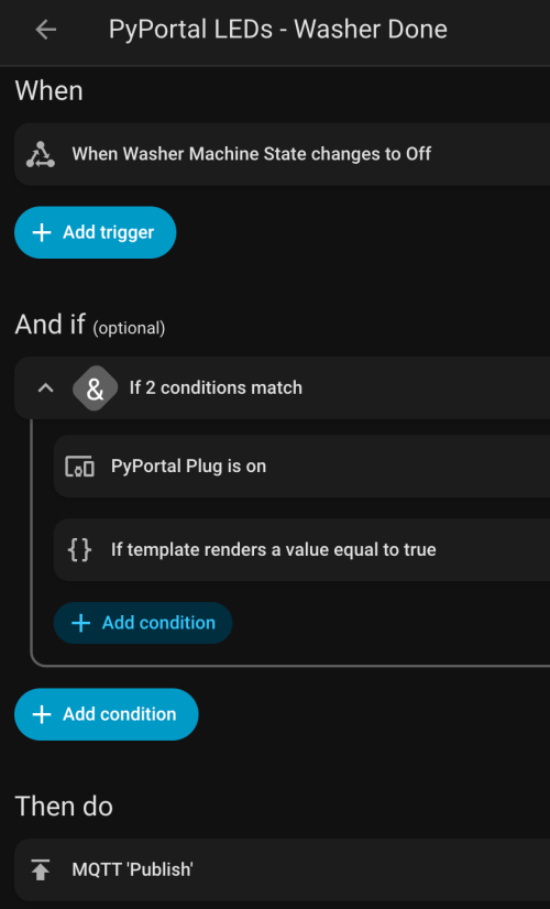
I can manually send these MQTT messages as shown in the demo, but the real power comes from automations. For example, the LEDs automatically pulse blue when the washing machine is done and pink when the dryer is done.
With the different effects and color combinations, the possibilities are endless. What kind of automations would you run?
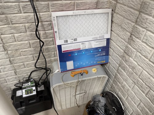
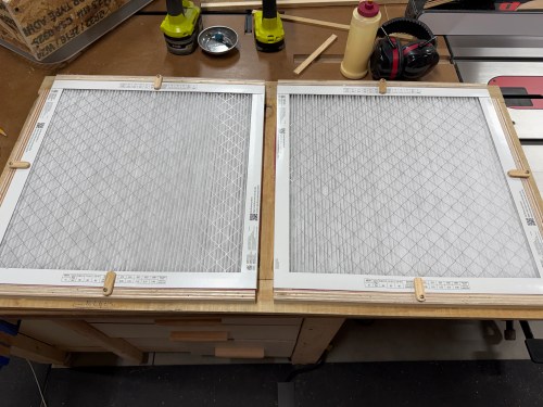
Over the years, I’ve seen many versions of a shop air filter, made from box fans and 20×20 inch furnace filters. A few years ago I picked up some old box fans on Facebook Marketplace and bought a pack of filters from Sam’s Club. They’ve been stacked in the corner.
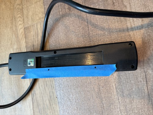
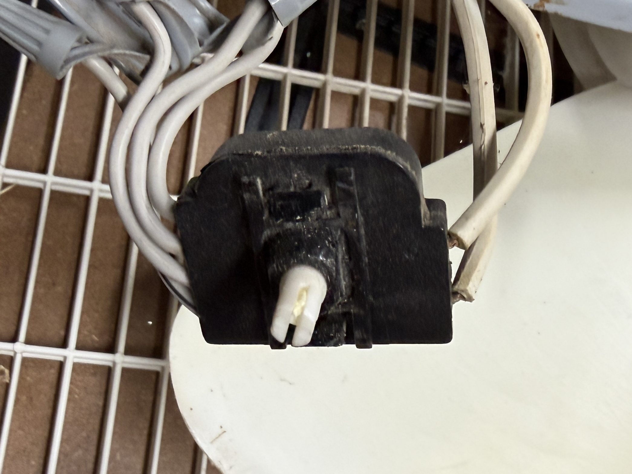
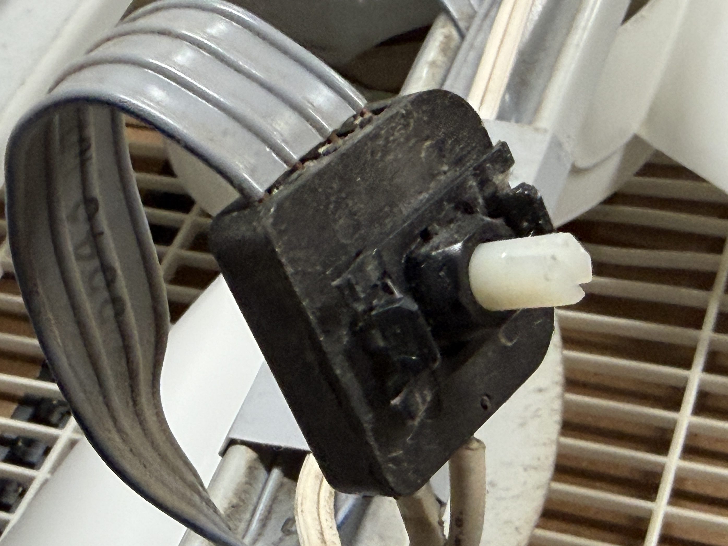
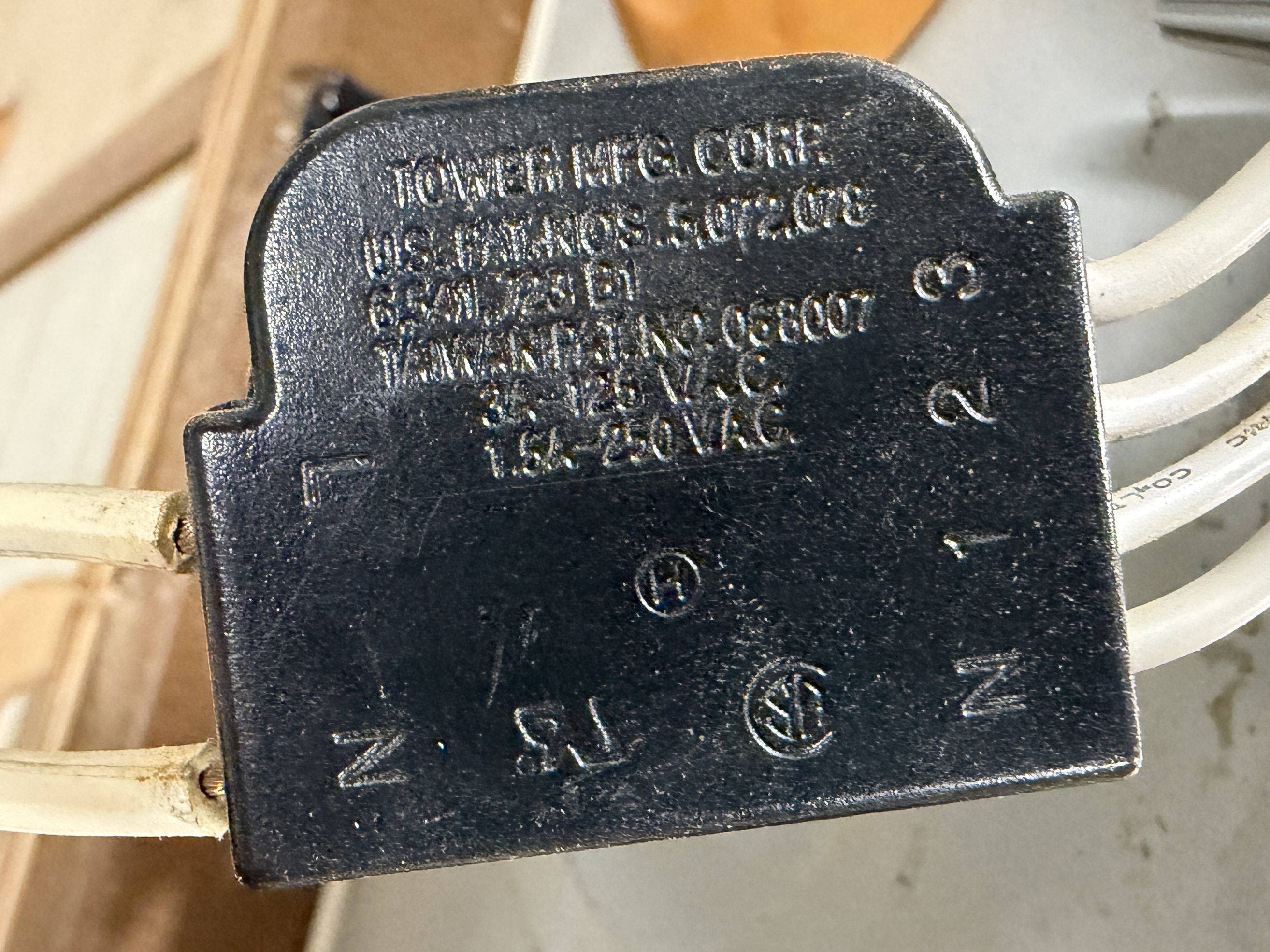
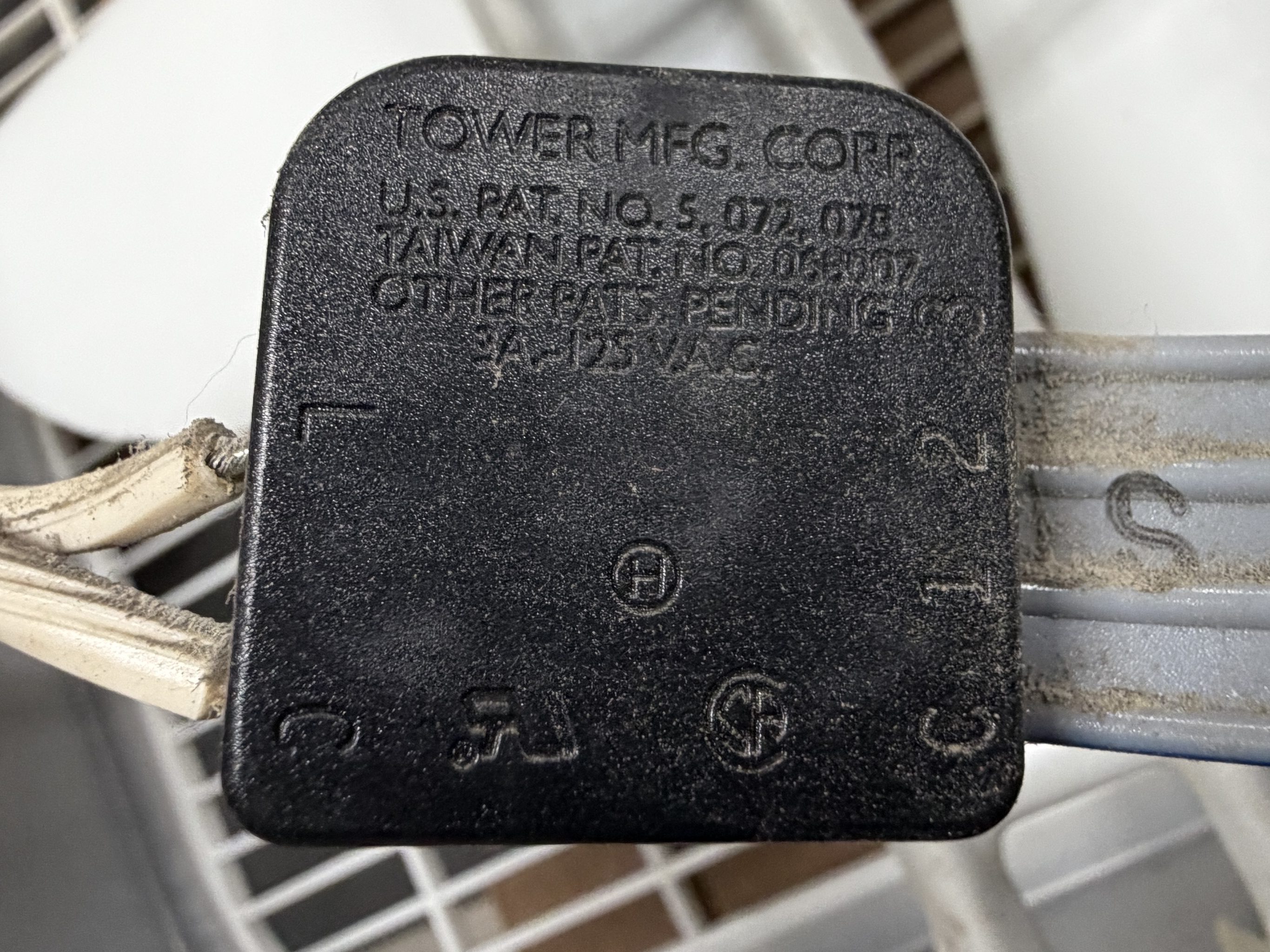
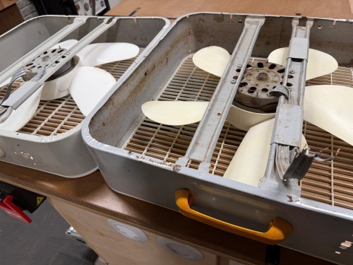
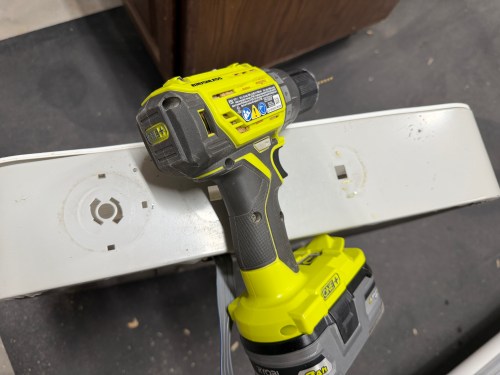
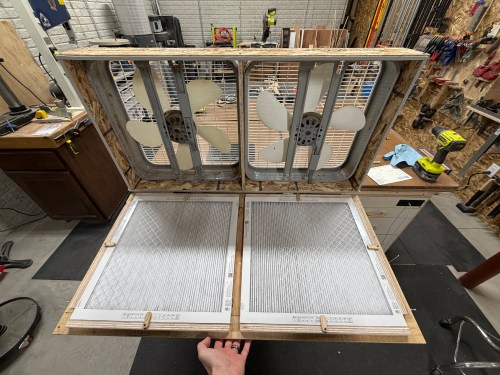
It was finally time to build my air filter. I removed the back covers, feet, handles, and knobs from the fans. I got my first look at the switches inside, which are nearly identical.
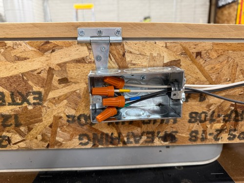
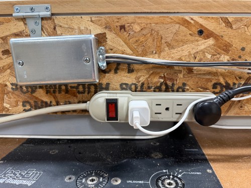
I’d easily be able to wire the fans together, so I removed the switches and power cords.
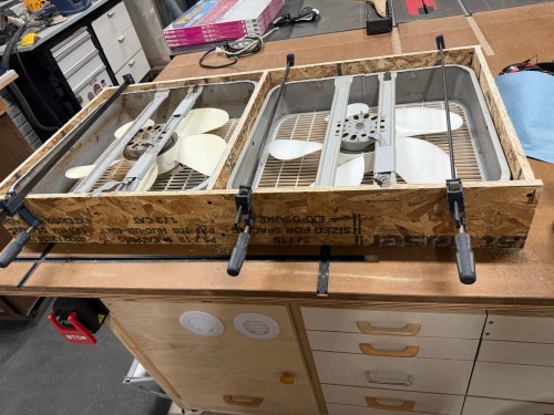
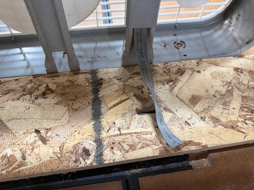
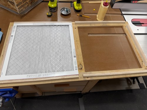
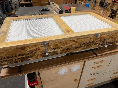
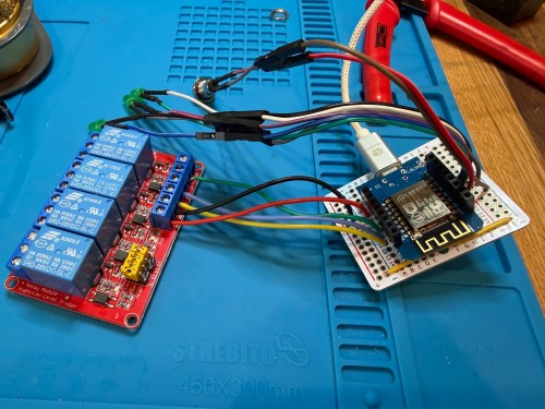
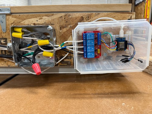
I put together a frame from OSB, cut slots to feed the wires through, and screwed the box fans in.
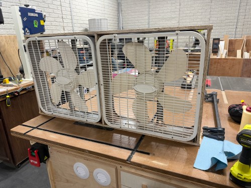
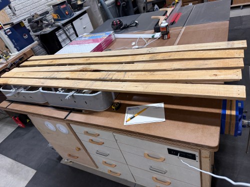
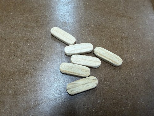
Then I grabbed wood that had been salvaged from a pallet to construct a door.
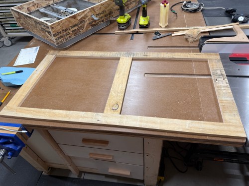
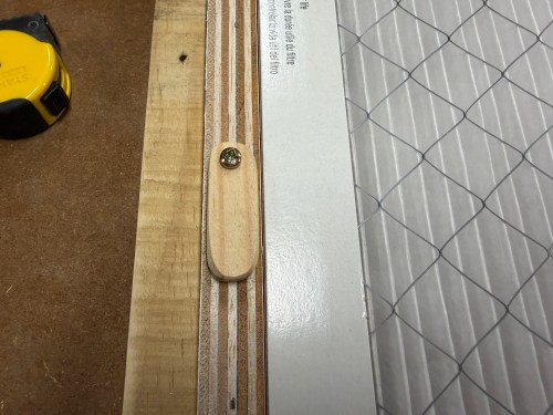
On the back side, I used glue and brad nails to attach plywood rails. I also made tabs to hold the filters secure.
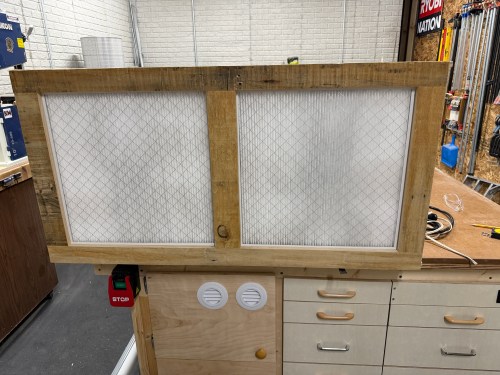
I attached the door with a couple hinges and made some notched tabs to hold the door shut.
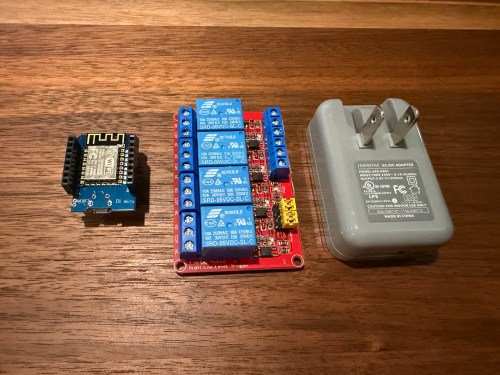
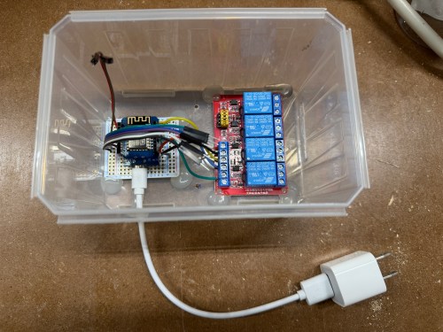
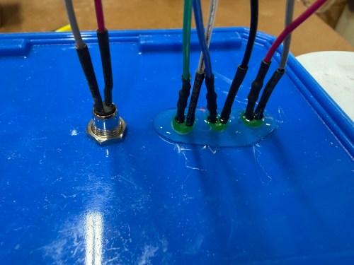
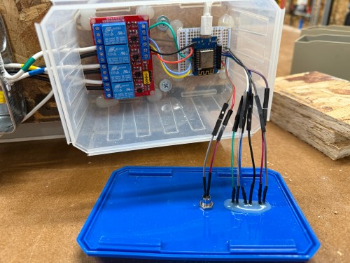
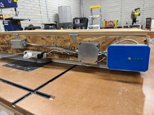
A plastic screw container was a good side, so I used hot glue to secure the boards and then wired up all of the fan connections.
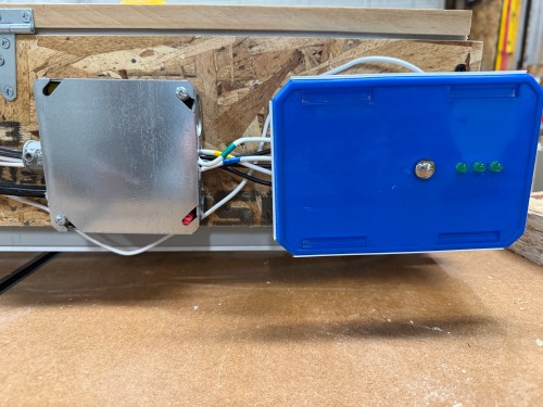
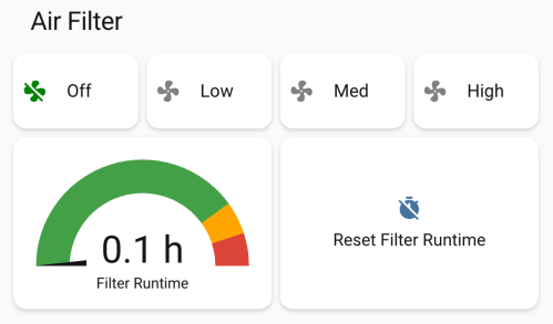
I’m not sure if I’ll ever use the button, but it allows me to cycle between the three speeds and turn it off. The three LEDs show which speed is currently running. The only thing I got wrong was reversing the low and high speeds, which was a quick fix in the ESPHome code. Speaking of the code, here’s mine.
I used Google Gemini to help and it had a great suggestion to track the run time and add a maintenance reminder when it was time to replace the filters.
In Home Assistant I created some automations. My dust collector uses a smart plug, so when it draws electricity, the air filter automatically turns on at high speed. When the dust collector turns off, the air filter continues to run for 15 minutes before turning off. If I had to remember to turn on the air filter all the time, it would rarely happen, so this is amazing.
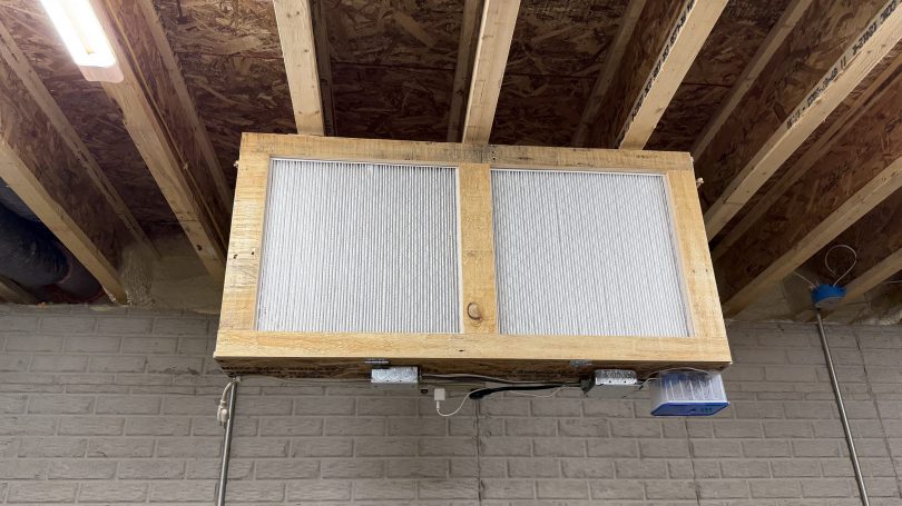
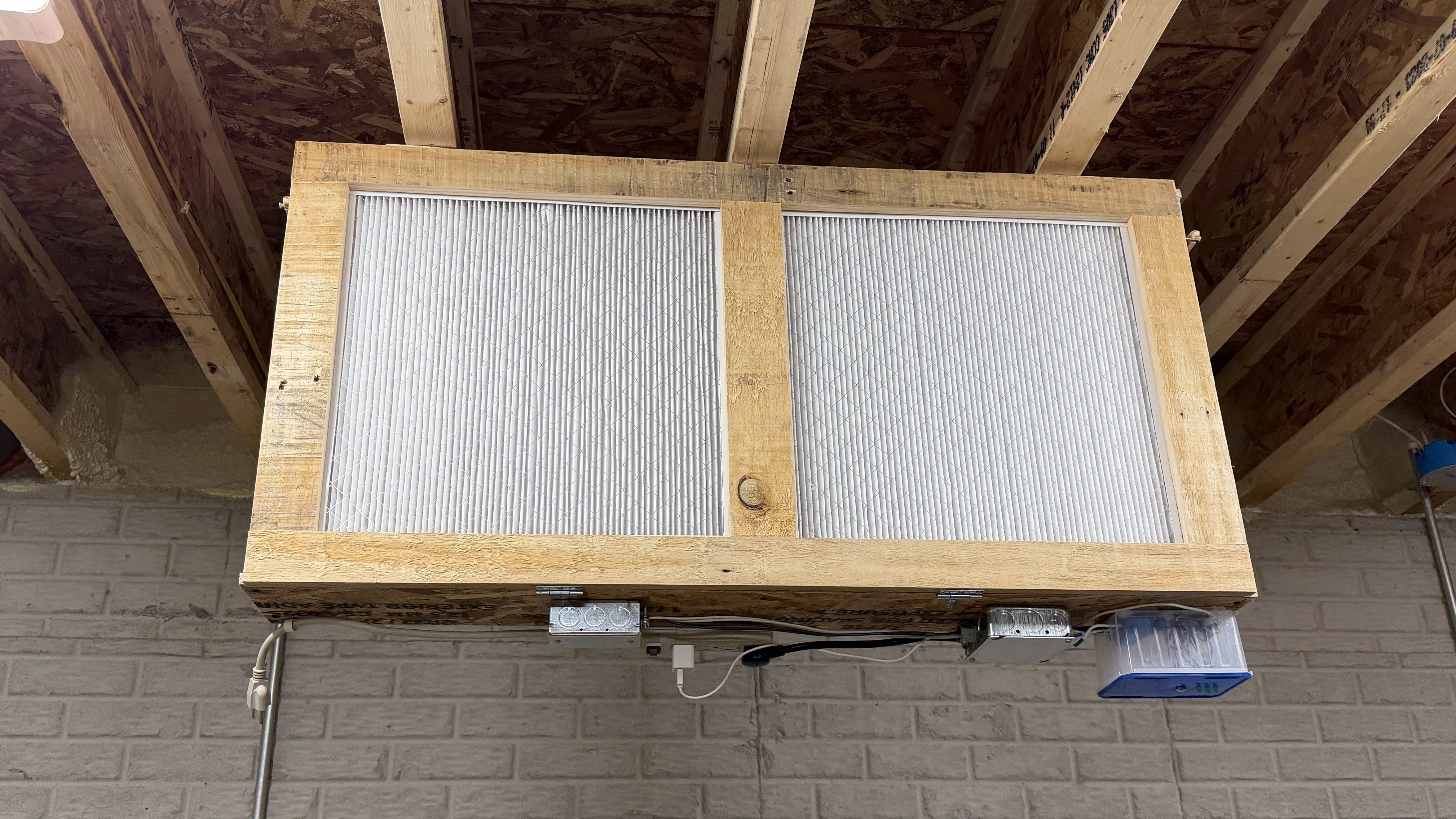
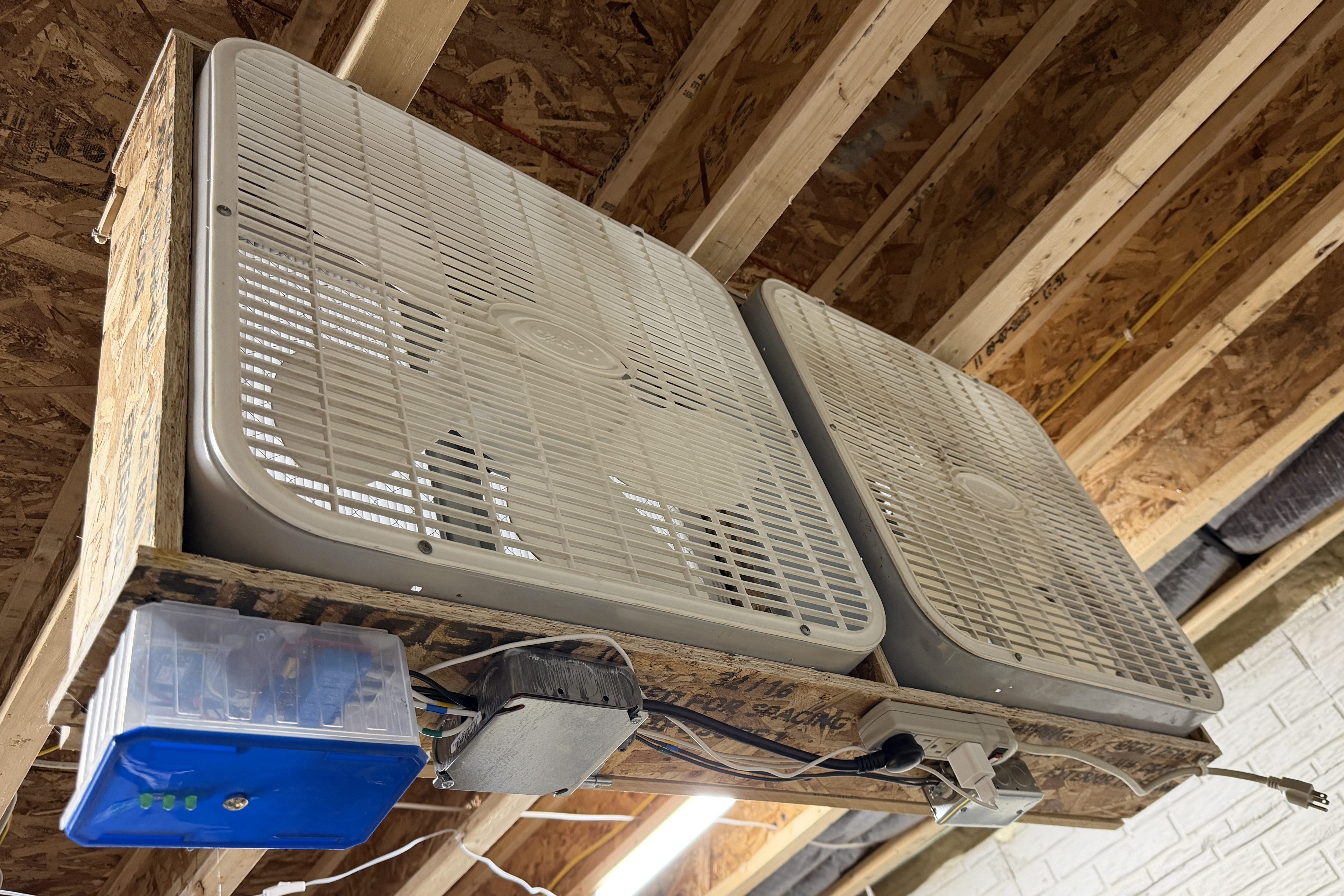
I’m still on lifting restrictions for several weeks so Brandi helped me install the air filter on the ceiling.
In our basement we have a baby gate, which surprisingly keeps our cat out of the gym and golf sim areas.
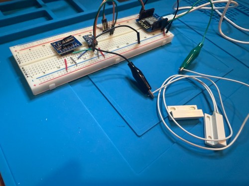
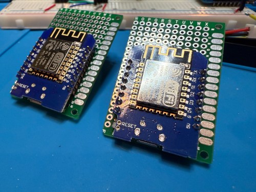
Sometimes we forget to close the gate, so I needed a sensor to monitor its state. I still had the breadboard from the air quality monitor project, so it was quick to add a magnetic door switch and test things out with the D1 Mini clone.
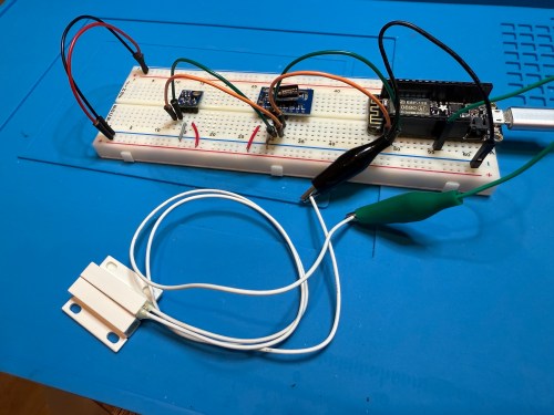
I have extra sensors, so those were kept in the project and allowed me to get rid of the shitty DHT22 I added to the golf remote. Everything worked, but I want to save my last two D1 minis and use them for something with the screens I have for them. So I swapped in an Adafruit Feather HUZZAH ESP8266, which I got with AdaBox 3 or 4 in 2017 and made minor changes to the code.
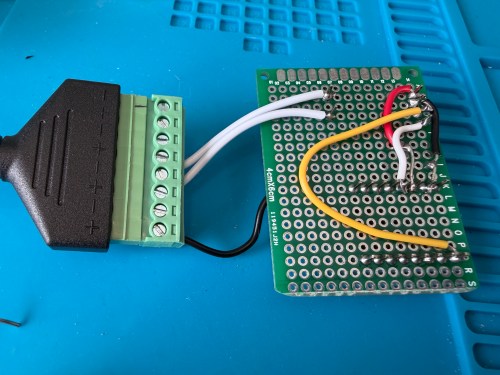
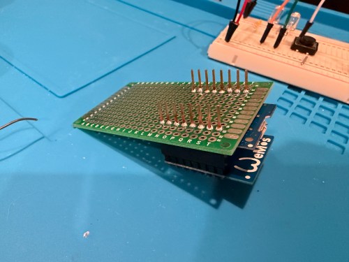
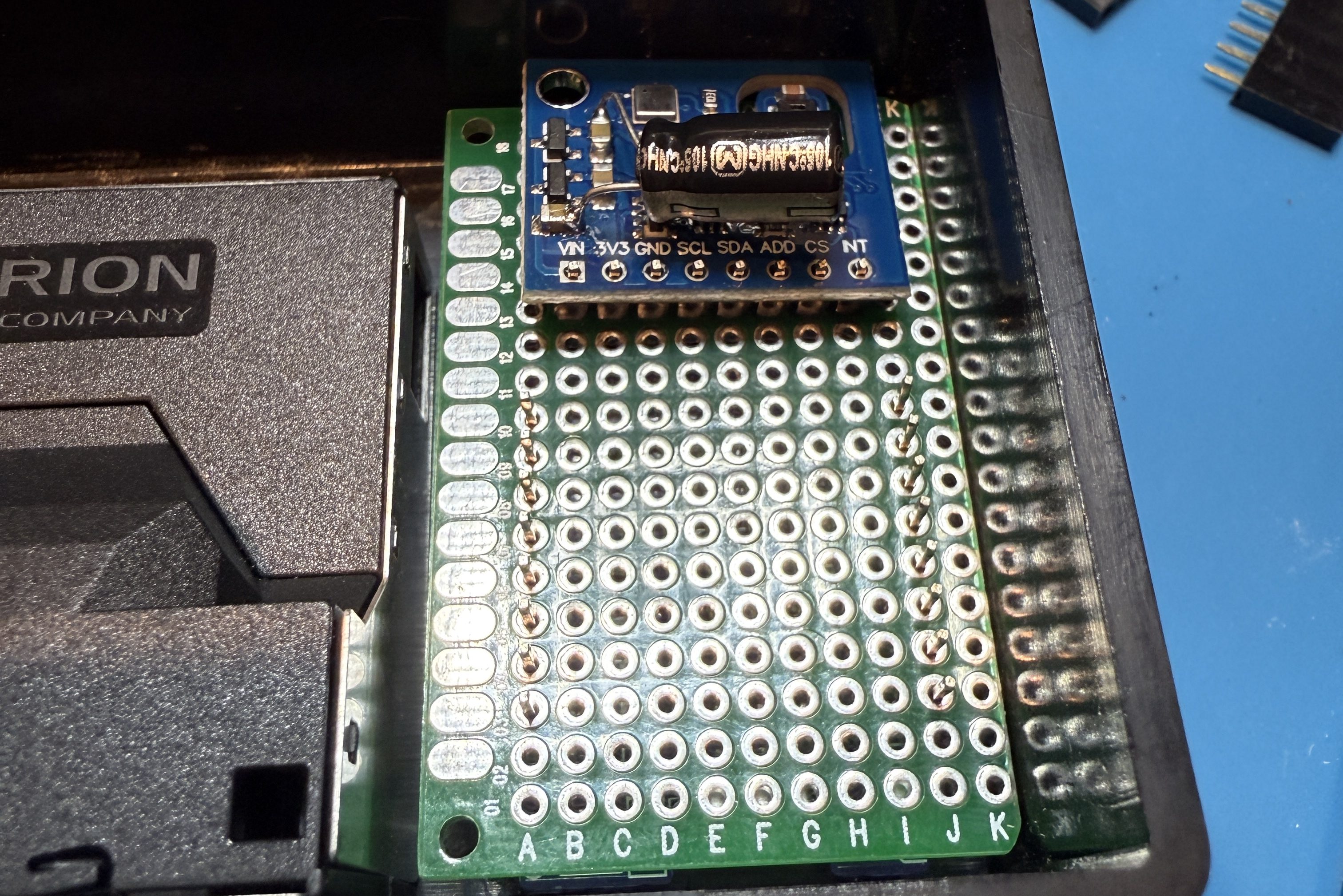
I figured I might as well use one of the fancy Adafruit Perma-Proto boards I had, which makes soldering all of the connections much easier. As a bonus it was nearly a perfect fit for the case.
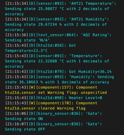
The magnetic switch and Si7021 will live outside the box, so those couldn’t get soldered yet. After connecting power I checked the ESPHome logs to make sure everything was working.
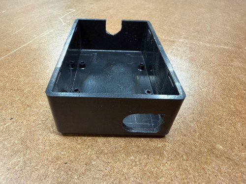
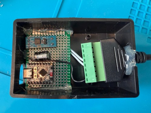
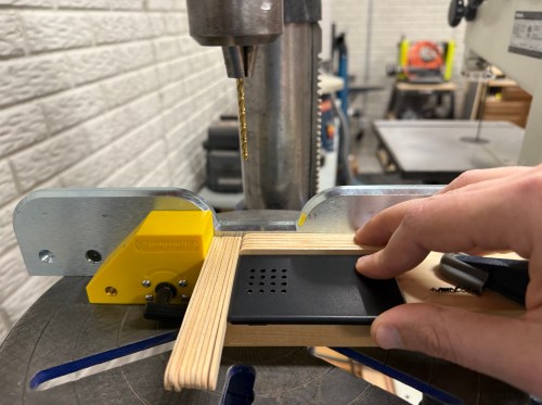
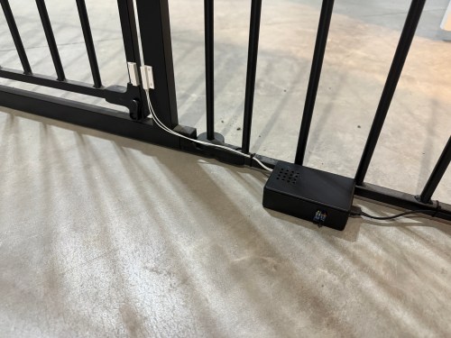
I cut holes in a project box, finished soldering, and used hot glue to secure the board..
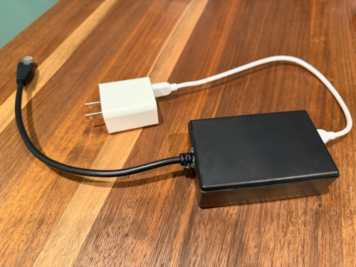
I reversed the swing of the gate, placed my device, and attached the two sides of the magnetic switch to the gate.
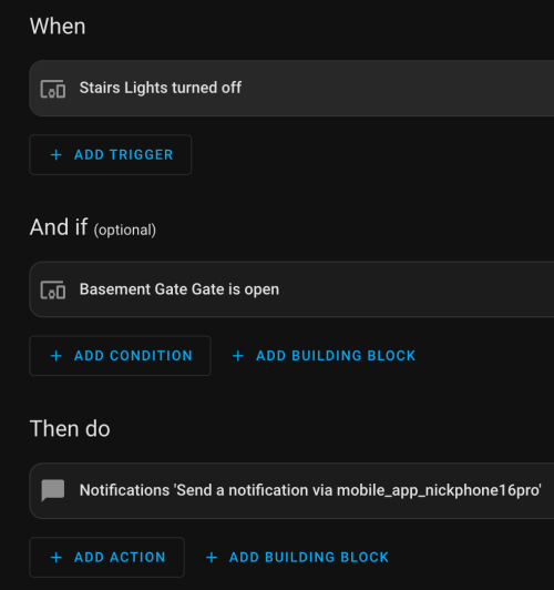
In Home Assistant an automation runs whenever the stairs light is turned off to check the state of the gate. If it’s open, a notification is sent to our phones.
I’m enjoying these little electronics projects, and it feels good to finally put various parts to use.
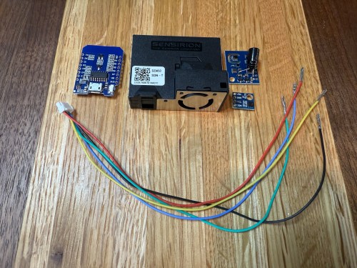
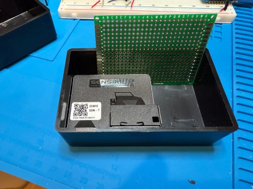
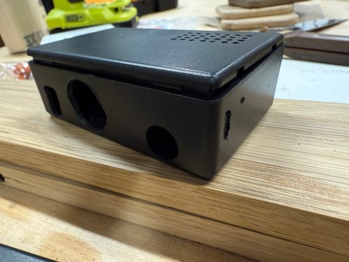
The upgraded IKEA air quality monitors I did work great, but the LED indication isn’t great for a bedroom and the fan noise was annoying in my office. So I wanted to create a couple of my own devices for those locations. I used:
The SEN50 is a big upgrade over the PM sensors used in the IKEA devices and I used the Si7021 in place of the BME280 I had used because I think they’re a bit better. I soldered 47µF electrolytic capacitors from a big kit I’ve had (similar on Amazon) to the ENS150 modules to improve their power.
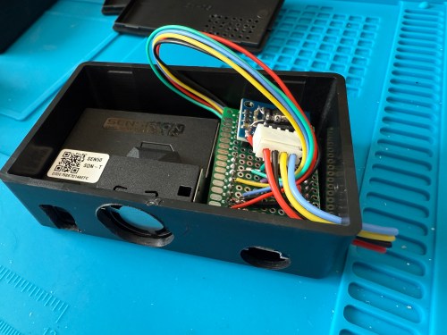
Then I attached 5 of the crimped wires to a 6P JST connector, which is what the SEN50 modules require. I’m note sure why buying the actual cable for these SEN50s are so expensive, but I got the entire JST kit for cheaper than a couple of the special cables.
All three sensors communicate with the microcontroller over I²C, so a breadboard test was easy to wire up. The SEN50 does require 5 volts instead of 3.3, so I’m glad I checked.
The ESPHome YAML code is very similar to the code used for the modified IKEA air quality monitors.
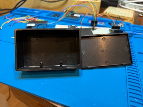
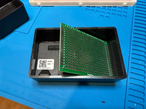
The project boxes had some standoffs on the bottom, which I snipped off and then sanded with a rotary tool. I pulled out my box of proto boards and found a size almost exactly double what I needed, so I cut out a sliver and ended up with a piece for each box. I also cut vent holes for the SEN50 sensors.
In order to get everything to fit I decided to put the microcontroller on the bottom of the board. After mocking things up I did all of the soldering. I was hoping to be able to mount everything with connectors so it could easily be taken apart, but there wasn’t enough room and I didn’t want bigger boxes.
I did some continuity testing along the way and everything worked when I connected power. With the boards ready I cut more access and ventilation holes in the boxes.
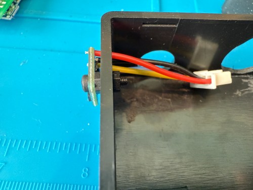
I soldered the Si7021 on to its wires outside of the enclosure so it wouldn’t be exposed to unnecessary heat and used hot gun to secure everything.
I’m really happy with how these turned out. Here’s a view of the office data on my Home Assistant dashboard.
This was definitely a project where I wished I had a 3D printer to design custom boxes. Some day, when I’m caught up on my project list and can give it proper attention. I know if I get one now I’ll spend a ton of time with it and neglect other projects in my pipeline.