Home Assistant Air Quality Monitors from IKEA Vindriktning

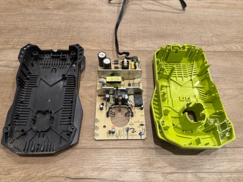
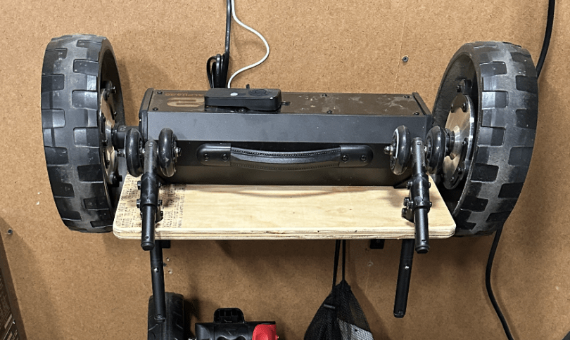
IKEA recently discontinued Vindriktning, their older air quality monitor.

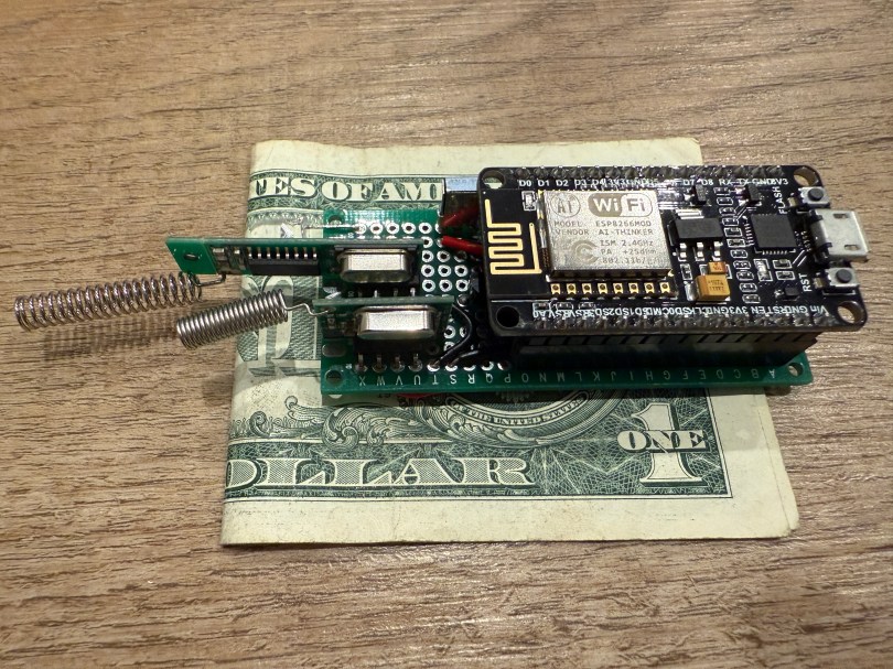
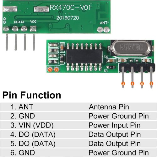
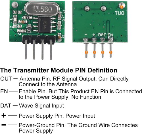
Inside the device, they put a cubic PM1006K particle sensor. I bought three for $16.95 each last year, because I’d seen people hack them by adding sensors and a Wi-Fi microcontroller to send all of the data to Home Assistant. For my modding I bought:

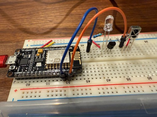
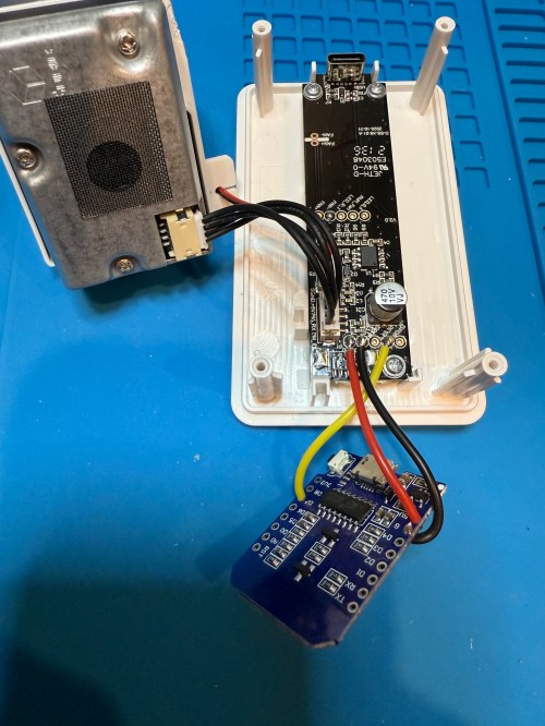
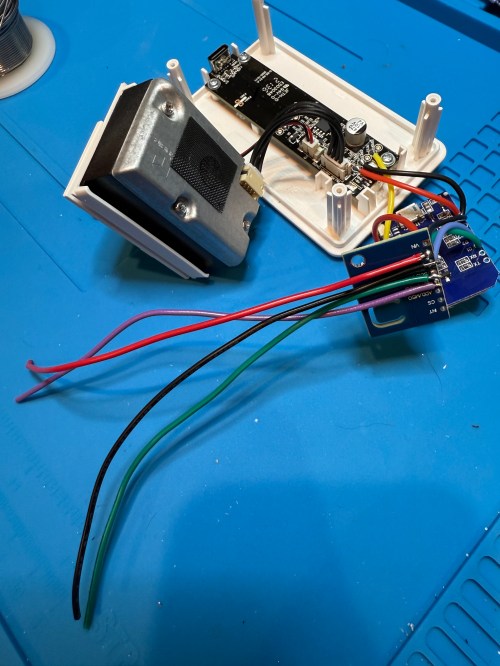
The YouTube video linked above is a great guide to follow. I didn’t connect wires to the fan or the light sensor since I had no use for them. I also didn’t stack my sensors because I wanted the BME280 to be outside of the enclosure, where it would be less affected by the heat produced by the ENS160 and D1.

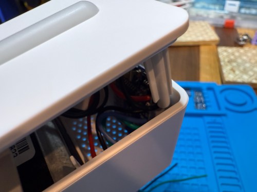
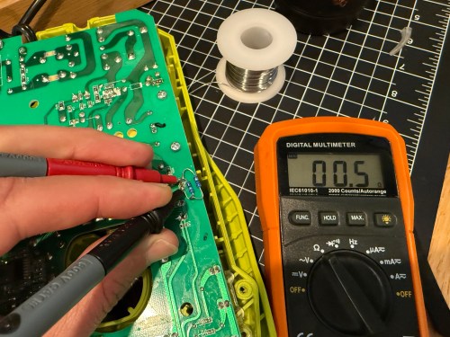
Even with the sensor outside of the case, the BME280 still reads high, because it heats itself up. I actually tested different lengths of wires and placements of the sensor before realizing I was still going to have to adjust the data. An ESPHome filter made the adjustment easy, which I did individually for each unit after comparing to a mobile Ecobee thermostat sensor. This is the code from the unit for my shop.

substitutions:
  slug: shop
  friendly: Shop

esphome:
  name: ${slug}-air-quality
  friendly_name: ${friendly} Air Quality

esp8266:
  board: d1_mini

logger:
  level: WARN

api:
  encryption:
    key: 'xxx'

ota:
  - platform: esphome
    password: 'xxx'

wifi:
  ssid: !secret wifi_ssid
  password: !secret wifi_password
  manual_ip:
    static_ip: xxx
    gateway: xxx
    subnet: 255.255.255.0

i2c:
  frequency: 100kHz

uart:
  - rx_pin: D7
    baud_rate: 9600

sensor:
  - platform: pm1006
    pm_2_5:
      name: PM 2.5µm

  - platform: bme280_i2c
    address: 0x76
    temperature:
      name: Temperature
      id: ${slug}_temp
      filters:
        - offset: -3.38
    humidity:
      name: Humidity
      id: ${slug}_humid
      filters:
        - offset: 7.63
    iir_filter: 16x

  - platform: aht10
    variant: AHT20
    temperature:
      name: AHT21 Temperature
      id: ${slug}_aht21_temp
    humidity:
      name: AHT21 Humidity
      id: ${slug}_aht21_humid

  - platform: ens160_i2c
    address: 0x53
    eco2:
      name: CO²
    tvoc:
      name: VOC
    aqi:
      id: ${slug}_aqi
      name: AQI
    compensation:
      temperature: ${slug}_aht21_temp
      humidity: ${slug}_aht21_humid

text_sensor:
  - platform: template
    name: AQI Rating
    lambda: |-
      switch ( (int) ( id( ${slug}_aqi ).state ) ) {
        case 1: return {"Excellent"};
        case 2: return {"Good"};
        case 3: return {"Moderate"};
        case 4: return {"Poor"};
        case 5: return {"Unhealthy"};
        default: return {"N/A"};
      }

These resources were a huge help when I wired everything up and made changes to the YAML code:

Here is how I’m displaying the data on one of my Home Assistant dashboards.

As I was working on this project I knew I wanted a couple more air quality monitors around the house, which will be finished soon.

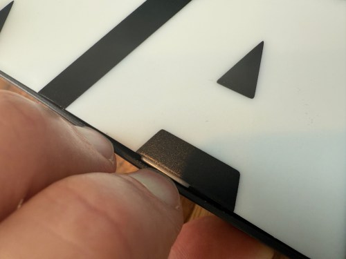
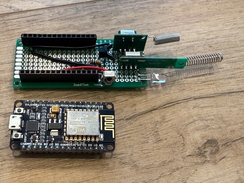
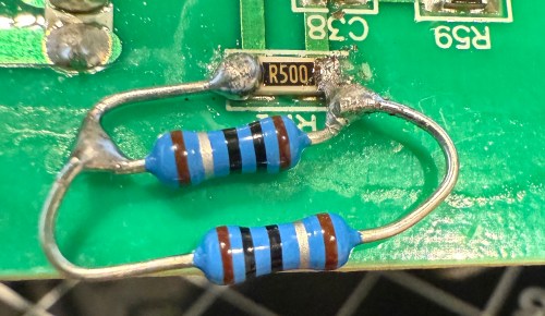
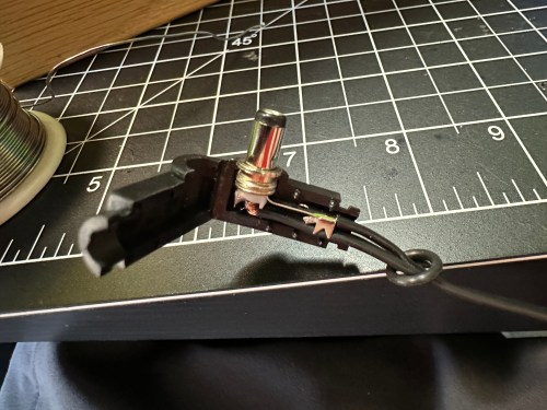
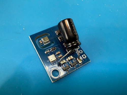
Update: I’ve had to make a small update by adding a 47uF capacitor to each ENS160 board, because they have power issues, causing the reading to stop for periods of time. My boards matched up with the right ones in the picture at that link. Here’s a picture of another ENS160 I modified, since it was a tight squeeze to made the modification on the devices I posted about here with everything already wired up. I also realized I was powering these through the 3V3 pin instead of VIN, so I fixed that.

I’ve also improved the display of the data on my dashboard by using mini-graph-card.

Modding a Star Wars LED Sign

Several years ago I bought this sign from T.J.Maxx.

When I plugged it in, I was disappointed. By default it was off with a button on the side to toggle between bright, dim, and off.

I put the sign in a display cabinet with all of the LEGO and I had wanted it to automatically turn on with the rest of the LEDs in the cabinet. I never got to it, so it sat on the shelf for years. Fast forward to setting up home automations at the new house and it was time to fix the problem. The only screw on the back was for opening a battery compartment, so I figured the front had to be snapped in. With a little careful persuasion I gained entry.

I figured the electronics were pretty basic and I was right. The quick fix was to connect the sides of the button/switch.

That worked, but I noticed how flimsy all the wiring was. I replaced the wires going from the USB connector to the board, which had been causing some flickering when bumped.

I was sad at the lack of LEDs though. I could do better, with minimal effort. I took out the circuit boards and found an old five volt LED strip.

With the help of some double-sided tape, I wrapped the strip throughout the case and then also used hot glue.

Much better!

Creating an ESPHome Remote Control Device with Infrared & Radio Frequency

In order to automate the processes of getting the golf sim ready to play and shutting it all down when finished I needed to create a remote control device. I’m using Home Assistant (HA) to run my home smart system (more posts to come), but two things involved with the golf sim aren’t connected to the network:

The projector has an infrared (IR) remote and the light has a radio frequency (RF) remote. I’ve done some things with IR and still had a stash of IR LEDs (for transmitting) and receivers. I’ve never attempted any RF stuff, so I ordered a 5 pack of 433mhz wireless RF transmitter and receiver pairs.

Since I’m using HA, I let ESPHome handle all of the main programming. All I had to do was wire everything properly and get the configuration correct. I made use of an old ESP8266 NodeMCU microcontroller and worked on the IR aspect of the project first.

When I took the picture I was using a 470Ω resistor, which I eventually switched to 100Ω, to increase the strength of the IR signal. The transistor is a PN2222A. Here’s the ESPHome configuration:

esphome:
  name: golf-remote
  friendly_name: Golf Remote

esp8266:
  board: nodemcuv2

logger:

api:
  encryption:
    key: "xxxxxxxxxx"

ota:
  - platform: esphome
    password: "xxxxxxxxxx"

wifi:
  ssid: !secret wifi_ssid
  password: !secret wifi_password
  manual_ip:
    static_ip: x.x.x.x
    gateway: x.x.x.x
    subnet: 255.255.255.0

remote_receiver:
  - id: GOLF_IR_RX
    pin:
      number: D1
      inverted: True
      mode:
        input: True
        pullup: True
    dump: all

remote_transmitter:
  - id: GOLF_IR_TX
    pin: D2
    carrier_duty_percent: 50%

I used the receiver to intercept the codes sent by the projector’s actual remote when pressing the Power, Input, and OK buttons. Then I created some buttons.

button:
  - platform: template
    name: Projector Power
    on_press:
      - remote_transmitter.transmit_nec:
          transmitter_id: GOLF_IR_TX
          address: 0x3000
          command: 0xFD02
  - platform: template
    name: Projector Input
    on_press:
      - remote_transmitter.transmit_nec:
          transmitter_id: GOLF_IR_TX
          address: 0x3000
          command: 0xFB04
  - platform: template
    name: Projector OK
    on_press:
      - remote_transmitter.transmit_nec:
          transmitter_id: GOLF_IR_TX
          address: 0x7788
          command: 0xE619

It all went very smooth. Next I connected the circuits for the RF components, which was straightforward. Here are the pinouts from the Amazon product page.

I soldered on the antennas (smaller one to the transmitter) and connected everything on the breadboard.

By using examples from the documentation I was able to intercept RF codes.

When I tried to recreate those codes through the transmitter the results weren’t matching up and the spotlight wasn’t responding. It took some trial and error to configure the various parameters of the receiver. Here’s the end result, with the combined configuration for IR and RF.

esphome:
  name: golf-remote
  friendly_name: Golf Remote

esp8266:
  board: nodemcuv2

logger:

api:
  encryption:
    key: "xxxxxxxxxx"

ota:
  - platform: esphome
    password: "xxxxxxxxxx"

wifi:
  ssid: !secret wifi_ssid
  password: !secret wifi_password
  manual_ip:
    static_ip: x.x.x.x
    gateway: x.x.x.x
    subnet: 255.255.255.0

remote_receiver:
  - id: GOLF_IR_RX
    pin:
      number: D1
      inverted: True
      mode:
        input: True
        pullup: True
    dump: all
  - id: GOLF_RF_RX
    pin:
      number: D6
      mode:
        input: True
        pullup: True
    dump:
      - rc_switch
    tolerance: 50%
    filter: 250us
    idle: 4ms
    buffer_size: 2kb # only for ESP8266

remote_transmitter:
  - id: GOLF_IR_TX
    pin: D2
    carrier_duty_percent: 50%
  - id: GOLF_RF_TX
    pin: D6
    carrier_duty_percent: 100%

After using the remote_receiver instances to get the button press codes I needed, I commented out that section of the code. If I ever need to add more functionality to my remote, I can enable the receivers at that point. Here are the button codes for the spotlight.

  - platform: template
    name: Spotlight On
    on_press:
      - remote_transmitter.transmit_rc_switch_raw:
          transmitter_id: GOLF_RF_TX
          code: '111001000000100100000011'
          protocol: 1
          repeat:
            times: 10
            wait_time: 0s
  - platform: template
    name: Spotlight Off
    on_press:
      - remote_transmitter.transmit_rc_switch_raw:
          transmitter_id: GOLF_RF_TX
          code: '111001000000100100000001'
          protocol: 1
          repeat:
            times: 10
            wait_time: 0s
  - platform: template
    name: Spotlight Green
    on_press:
      - remote_transmitter.transmit_rc_switch_raw:
          transmitter_id: GOLF_RF_TX
          code: '111001000000100100000111'
          protocol: 1
          repeat:
            times: 10
            wait_time: 0s

Then I was able to use both sets of buttons in scripts, which can feed to Alexa for voice commands.

Once everything was tested I wired and soldered a more permanent circuitboard. I included a folded dollar bill for scale.

I was planning to mount it in the ceiling, but the IR was having trouble, because the projector’s receiver faces the ground. Mounting it to the side of the PC cart worked great.

This was a lot of fun!

Update: Less than a week later I’ve already modified it, by adding a DHT22, which reports temperature and humidity. Might as well use that empty D7 pin on the microcontroller.

Attempting to Revive Knockoff Ryobi Batteries

I have a couple of 5 Ah batteries and both of them stopped charging. They knockoffs from Amazon, with a brand name of Biswaye on them.

One was completely dead and wouldn’t even register on a usual charger. The other showed a defective status. When I put the multimeter on, it read about 15 volts.

This often means some of the individual cells are bad. Before opening it up, I threw it on a Ryobi P119 slow charger, which can sometimes revive cells that are too low for the more complex battery chargers.

After a couple of hours I tried the battery on a regular charger again, but it still showed as defective. So I tore into both batteries, hoping I might be able to get one working battery out of the two.

On the dead battery all 10 cells read zero volts on the multimeter. I wouldn’t be swapping any of those in to the other battery. It’s not safe to try pumping anything into cells depleted that much, so I recycled them at Batteries Plus.

Two of the cells on the defective battery read very low voltages. I don’t have any spare 18650 lithium ion cells and it’s not worth it to buy some since I have enough working Ryobi batteries in my rotation. As a last resort, I put the battery on the little charger to see if it would slowly charge the depleted cells. I had nothing to lose.

I let it go over 6 hours and unfortunately the voltage didn’t jump up on those bad cells, so I still can’t use the battery pack.

Attempts like this don’t always end in success, but it’s a fun opportunity to learn. This battery pack has plenty of good cells, so I’ll save it in case another battery needs replacement cells.

Repairing a Ryobi P117 Intelliport Charger

Last week while cutting some walnut with my Ryobi track saw, it kept stalling on me. Turns out the battery was nearly dead because the charger stopped working and the status LEDs weren’t lighting up at all when plugged in.

I opened up the charger and didn’t see burn marks or swollen capacitors anywhere.

Then I found a video on YouTube and sure enough, the resistor at R71 was wide open, reading 152 kΩ on the multimeter.

It’s a surface mount resistor labeled R500, which means 0.5 Ω. I don’t have any resistors that size, so I soldered in a couple of 1 Ω resistors in parallel.

It’s not pretty, but it properly read 0.5 Ω on the multimeter.

I put it back together, plugged it in, and the red LED lit up. Took it down to the shop, put a battery in, and the charger is back in the rotation!

Swapping an AC Adapter Cable

I was given a replacement AC adapter for an Acer laptop, which isn’t compatible with the Dell Optiplex micro PC I wanted to use it with. The output is close enough to work, so I looked for an adapter to convert from the 5.5×1.7mm connector used by the Acer to 4.5x3mm used by the Dell. I couldn’t find an adapter anywhere! I did however find a pigtail adapter on Amazon for about $8 I could wire in. Here’s the original connector and the new cable.

I opened up the power brick.

Then I made sure to test the output voltage and the polarity of the wires and connector with a multimeter. I noticed an unused spot for LED1 on the circuit board, so I figured I’d see if connecting a second LED would provide some other status indicator.

All it seemed to do was take over and disable LED2. So I removed it and left the original green LED. I desoldered the original cable, which only had positive and ground wires. The board had a spot with an S, which I assume means “signal,” so when connecting the pigtail, I soldered the blue wire there.

I checked the voltage on the new connector and it was as expected.

I plugged in the Dell and everything seemed to work. I cleaned the old thermal paste off the 3 components that screwed to a big metal heat sink and put on new paste. When I went to close everything I realized the black wire was too short, preventing the cable from reaching the hole in the power brick. I had to solder on a short extension and cover it with shrink tube.

Tucked everything back in the power brick, snapped it together, and it’s good to go.

Boldport: PissOff

PissOff was project #9 of the Boldport Club, which was before my membership, but I bought it in December of 2018 with my credits when the club closed. I recorded an unboxing video on February 21, 2021 and I guess I ran out of time for the build. The project sat on my shelf for almost three more years before I finally assembled the circuit, which ended up being five years after ordering it!

The kit created a proximity sensor via IR and combined it with annoying noises. With so many surface mount components, this was one of my most challenging electronic soldering builds. I really struggle when an IC has a lot of pins. At one point I tried some other solder and realized what I’d been using was junk, so it went right in the trash.

I screwed up the placement of a couple of SMD capacitors, but caught myself soon enough to remember which ones needed to be exchanged. The other mistake I made was swapping locations between the IR phototransistor and diode, which I didn’t catch until testing. After putting them in the correct locations, everything worked!

Here’s a 8x speed run of the unboxing and some footage of Ninja’s testing.

Useful links:

Alphard Club Booster V2 and a DIY Rack/Shelf

I prefer to walk golf courses. It’s great exercise, gives me time prepare for shots as well as reflect, and it’s faster than riding. I bought a Clicgear 3.0 three wheel cart in 2011 and with some minor fixes over the years it’s worked great.

I’m not getting any younger and I want to keep walking as long as I can, so I’ve thought about a motorized push cart. Then I came across the Club Booster V2 by Alphard (save $50!), which converts your own push cart into a motorized one. The reviews were awesome so I ordered a refurb unit for $647. Here’s my first test after assembly.

I was impressed, but the dragging front wheel while turning didn’t work very well, so I quickly ordered the Swivel Conversion Kit for $89. The kit replaced the front wheel with an axle where the original back wheels mounted to make it a four wheel cart with a swivel front. It makes a huge difference for maneuverability and stability.

By the time I finished my first nine holes I felt very comfortable controlling it. I’ve played two 18 hole rounds and this upgraded cart let’s me play faster and leaves me fresher for the back nine. I’m surprised how much energy I save not having to push the cart. I’m thinking about doing a detailed review post.

There were two problems though. The parts took up too much floor space in the garage and looked messy. I also forgot to take the wheelie bars for the first round I played.

I needed some type of rack to keep things organized, help me remember to grab everything, and make changing easy. I thought about having slots for the axle or something to prevent the unit from falling to the floor. After cutting a piece of plywood and laying things out, I realized a simple shelf with holes for the wheelie bars is all I needed.

Just what I needed. I love a quick build.

With a motor this is a vehicle for my golf clubs, so it needed a name. I’ve been struggling to think of anything, so I asked ChatGPT.

Those are some good ones and I chuckled. Brandi’s idea was to call it R2-D2, but I don’t like reusing a specific name. I like the style, so I settled on CB-V2 since the unit is like my own droid.

Update on the Milwaukee M12 Heated Jacket Fix

Last month I wrote about some failures with Brandi’s Milwaukee M12 Heated Jacket and the higher capacity battery they sent is working great for her. I ended that post with sort of a prediction…

I might end up getting a right angle jack to help with the strain relief. We’ll see how this holds up.

Yeah…

It hadn’t failed, but was heading that way. I didn’t help that I don’t have any heat shrink large enough to go over the end of that barrel jack. I ordered a pack of right angle barrel jacks from Amazon and soldered the wires in.

Didn’t work. The jack wasn’t long enough or the wrong size to make a good connection to the power source. I wish I had checked connections before soldering the wires on. I ordered a different style of jack in two sizes, 5.5 x 2.1 mm and 5.5 x 2.5 mm.

The 5.5 x 2.5, on the left, turned out to be the correct size. After confirming (multiple times) the positive and negative sides of each connection I slipped on some heat shrink, soldered the wires to the jacket, and blasted flames at the heat shrink.

The right angle is a much better connection because of how the battery sits in the jacket pocket and the extra length will help with strain relief. I feel better about having a soldered connection as well. It’s a win all around.