AdaBox003

AdaBox003 arrived! It’s my first box as an official subscriber. I bought 001 and 002 through the Adafruit store, but as a subscriber you get: The new box automatically each quarter. A cheaper price – $60 with free shipping. Extras! Each AdaBox has a theme and this one is right up my alley… THE WORLD OF IoT – CURATED BY DIGI-KEY IoT is […]

Blog in a Box Paparazzi

wapi-512Happy Pi Day! I figured I better post something Raspberry Pi related today…

This weekend I played around with Blog in a Box which was recently released by our Tinker team at Automattic.

A quick and easy way of putting WordPress onto a Raspberry Pi.

BIAB ships with modules to use the Raspberry Pi camera and SenseHAT. I hadn’t used my Pi camera yet and had a fun idea to hack around with.

blog-in-a-box-ssh

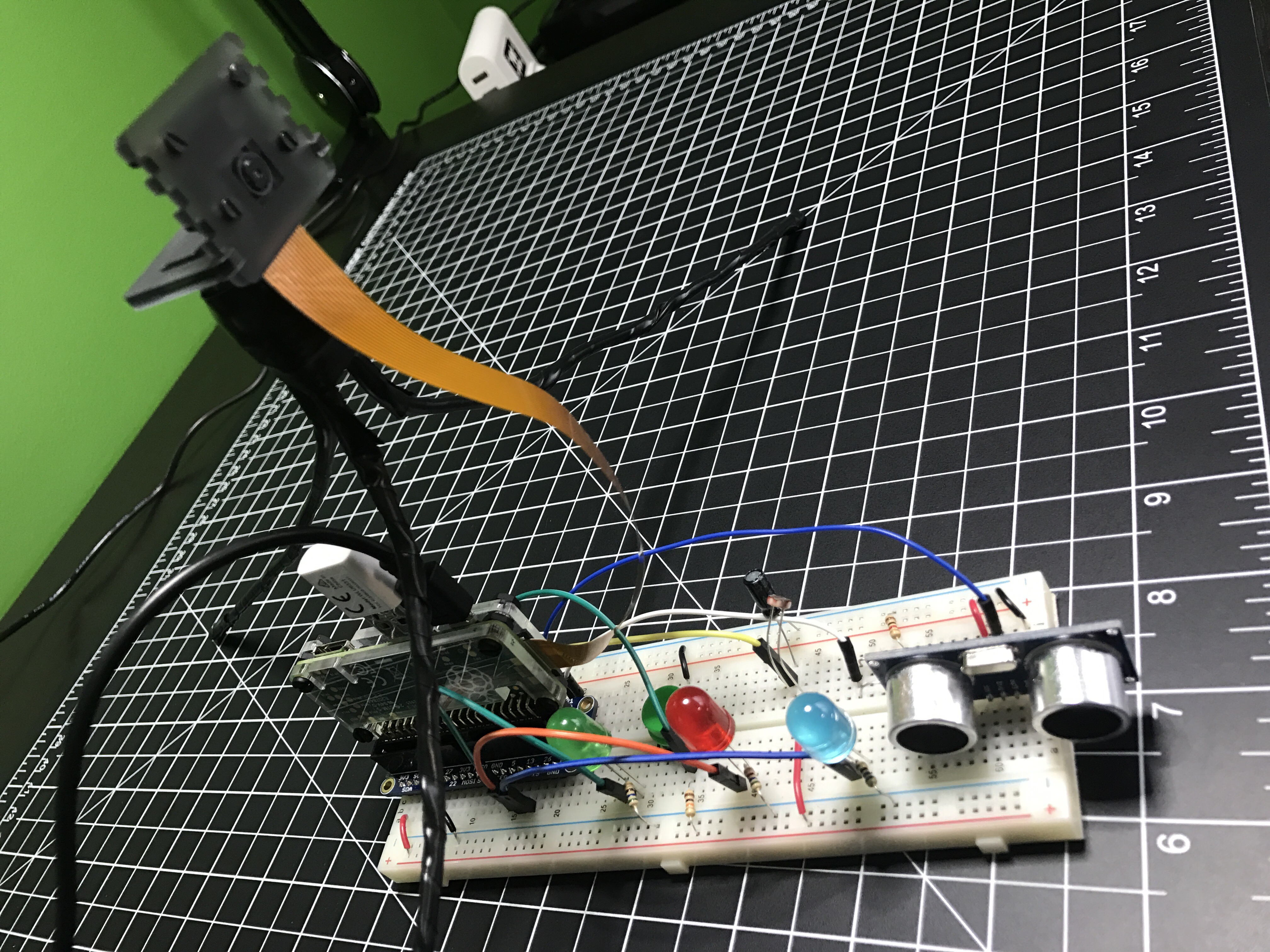
The camera module allows you to take a photo on a schedule by setting a period of minutes, hours, or days between each photo. I wanted to have a little more fun, so I wired some other electronics up to a Raspberry Pi Zero and wrote a little Python program.

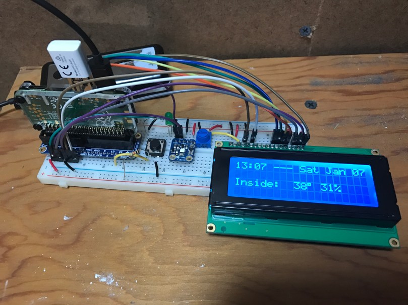
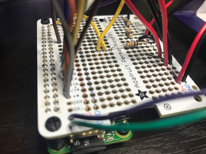
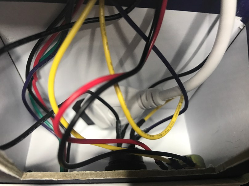
The first electronic element was a simple button. Press it and a picture is taken. Next up was a photocell (light sensor). When the room quickly changes from dark to light, it’ll take a picture. Since the Pi doesn’t have analog inputs, I went with a neat technique of measuring the sensor as a resistor used to ‘fill up’ a capacitor. The last element was an ultrasonic sensor I haven’t used yet either. It measures the distance to an object in front of it, so I’m kind of using it as a motion detector. Walk in front of the sensor and a picture is snapped. Due to mismatched voltages on the PI’s GPIO and the output signal of the rangefinder, I had to use some resistors to create a voltage divider circuit.

To create visual feedback I wired up an LED for each of these 3 components. When one of the components triggers a photo, the associated LED lights up until the process is complete.

I named it Blog in a Box Paparazzi. Of course the code and wiring info are available on GitHub. Should be easy to adjust if you have other sensors, buttons, switches, or whatever you want to trigger photos. Let me know if you try something different.

AdaBox002: Make Robot Friend

Adafruit’s 2nd AdaBox is everything needed to build a full functioning robot, controlled over Bluetooth via their Bluefruit app. When I got it a couple of months ago, I put it together and wrote a bunch of notes for improvements I wanted to make. I finally got around to spending some time on it. Adafruit’s learn guide and the associated […]

Solar Power

I saw last week’s Daily Post Photo Challenge was “Shadow”. We don’t get much sun in the winter, so I decided to flip the challenge on it’s head. A shadow is the enemy of solar power, right? A couple of months ago I had bought a bunch of electronics for a solar powered project idea. I don’t […]

Garage Temperature Sensor & Monitor

I’ve been working on this project here and there for a few weeks, with most of the early work being experimentation. Everything is now up and running and it’s “deployed to production” so to speak. This was my prototyping setup…

After wiring everything together and repurposing a cardboard box, here is a short video to show the final product.

A few notes on how it works:

  • The button toggles monitor mode. The LED inside the button indicates if Monitor mode is on/off.
  • When monitor mode is on and the desired temperature is reached, I get a notification.
  • I should have shown the knob, but all it does is adjust the LCD’s contrast.
  • The thing on the top left of the box is the sensor chip for reading temperature and humidity. Originally it was inside the box behind a little window there but it was picking up too much heat from the Pi and LCD in there.
  • The backlight color of the LCD is based on the measured temperature and updates each time new temperature is read. Anything 32° Farenheit and below is blue, 80° and above is red, and everything in between is based on where it falls within that 32-80 range. As you can see in the example, 48° is a lighter blue. A few degrees warmer and I think it would have started to look more green.
  • Outside temperature/humidity is pulled in from the Dark Sky data in my Home Assistant setup (which I’ll post about soon).
  • Data is sent to Home Assistant via MQTT.

home-assistant-garage.png

Really happy with how things turned out. The Pi  I wrote this in Python and it’s all available as home-assistant-temperature-monitor on GitHub if you want to make your own or use some of the code for your own project. There is also a list of all the components used.

Here are some pictures I took while assembling the enclosure/box.

Making sure the Pi and attached Hat fit right after drilling the holes. Seemed like there was so much room at this point.
img_8663
Everything soldered to the HAT. Amazingly I didn’t make any mistakes and everything worked on the first try. A good prototyping setup, having pictures of my final prototype, and keeping a list of where everything connected was invaluable.
The Raspberry Pi, Hat, LCD, USB cables to power and WiFi, and all of the other wiring jammed in! Reaching inside to get things screwed through the box wasn’t easy.
There is a lot more room in the other part of the box where the sensor, button, and knob are. Nice for the WiFi adapter and cable to come across and have some room.

Update: Adafruit released a new Learn guide that does some similar stuff to this project.