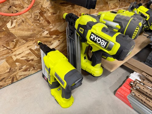
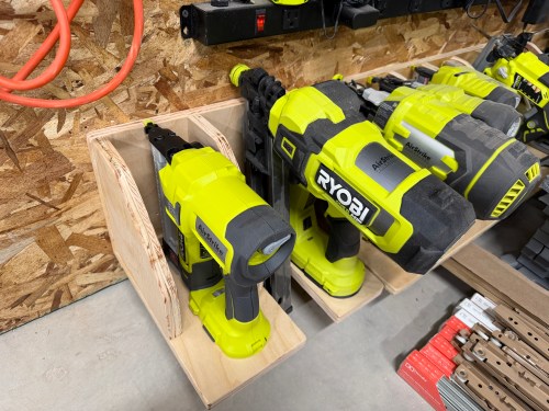
Quick build this weekend to expand my Ryobi tool storage wall (which moved to the new workshop) with spots for the framing nailer I got last year to build the shop wall and a narrow crown stapler I recently bought on sale.
As I’m writing this and seeing the pictures, I butt jointed the back and bottom incorrectly, which is why it’s too tall and not deep enough to match up with the old spots. Oh well!
It’s great to be back in the shop again and getting it more organized.
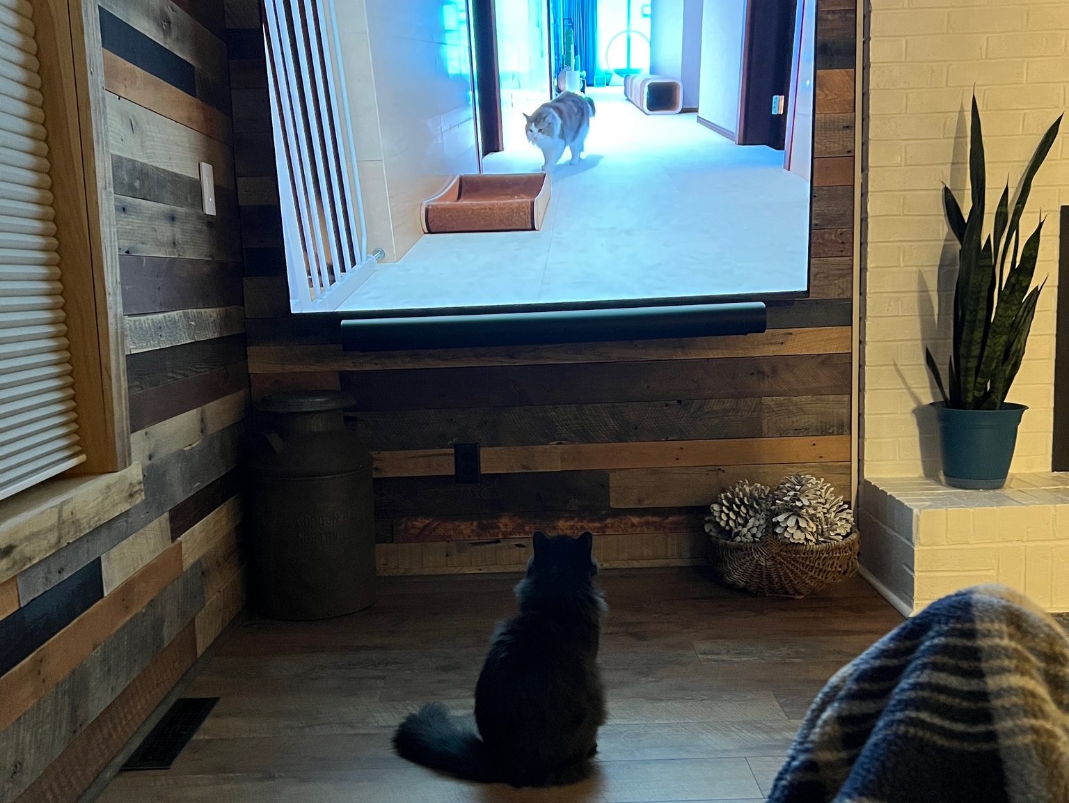
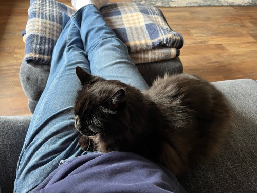
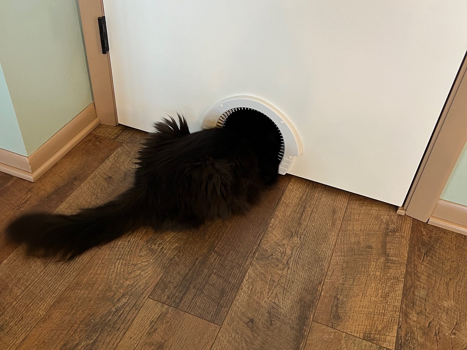
When Brandi moved in she brought her black cat, Ninja, with her. I wasn’t too sure about him because I’d never liked cats. With my job working from home, he quickly became my little buddy and turned me in to a cat guy.
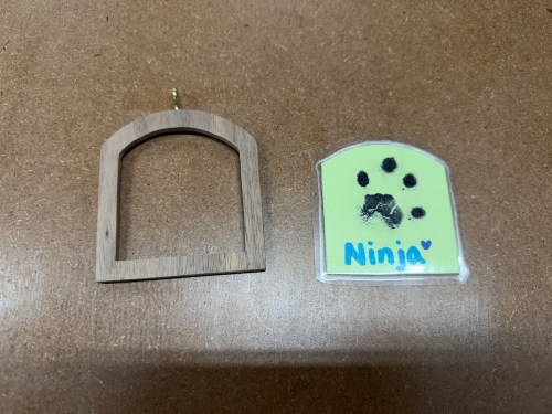
Ninja got sick and we lost him at the end of August, which was really hard. 😿 He was such a good kitty! The vet sent us a sympathy card with his paw print.
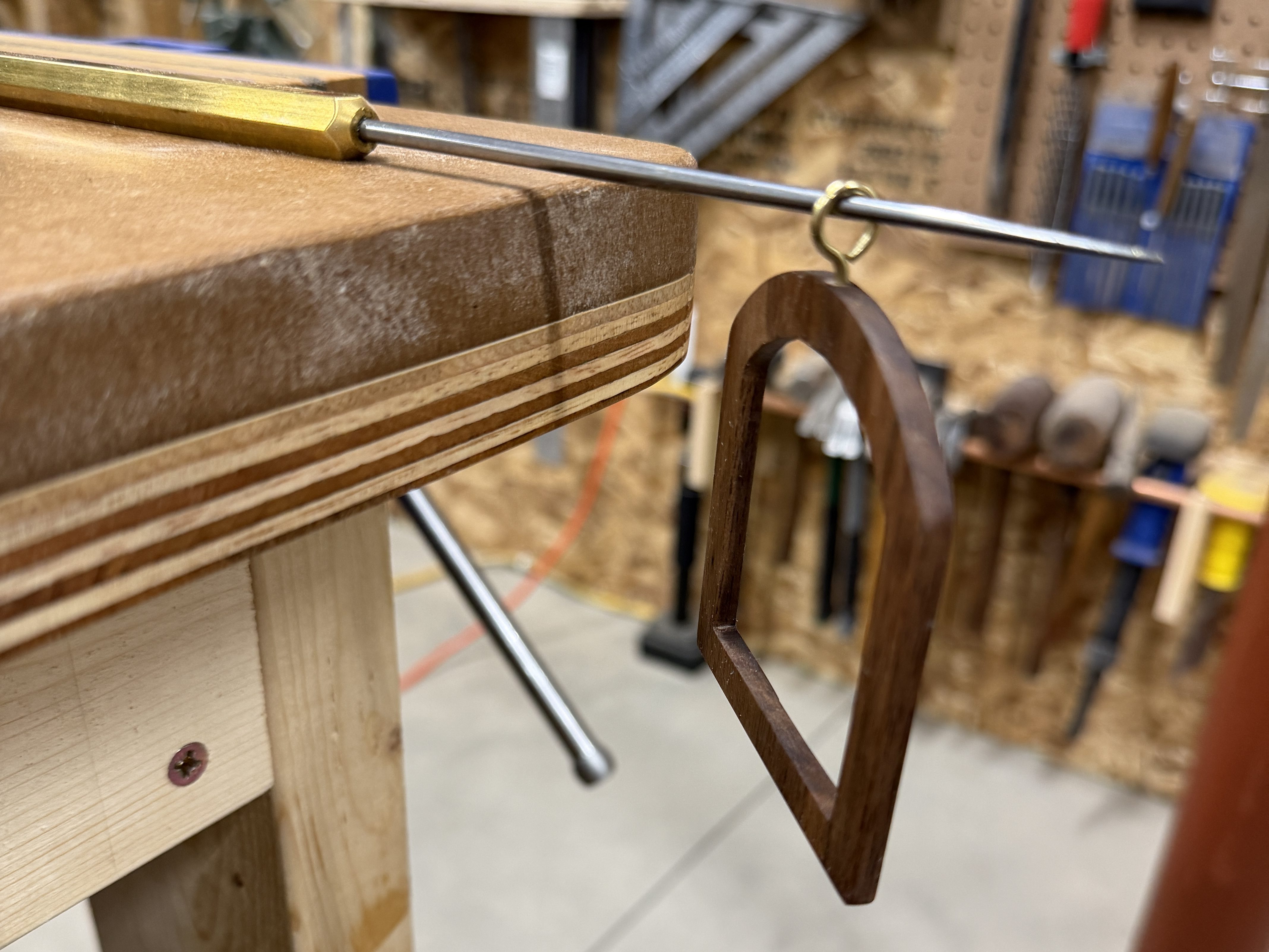
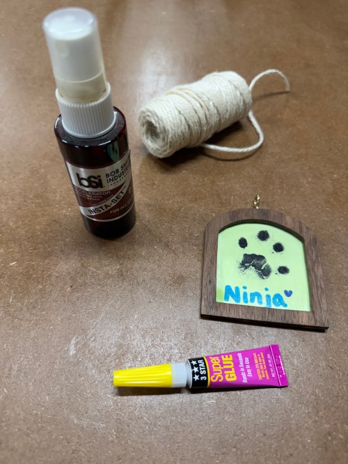
Since holidays are always a good time to remember, we decided to preserve the card in this year’s Christmas ornament and we’ll always have it. Brandi wants to start learning to use some of the tools in the shop, and she got to use the band saw, scroll saw, and sanders while helping to make the frame.
Check out our previous ornaments from 2021, 2022, 2023, and 2024.
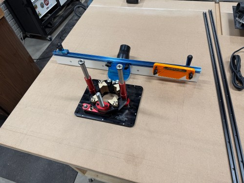
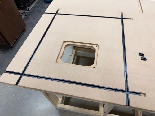
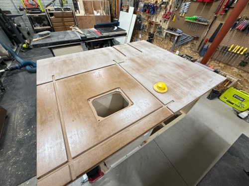
First, I had to figure out exactly where to install everything. I placed the fence and lift (upside down) on the table to get a feel for it. Then I outlined the lift and drew in the T-tracks.
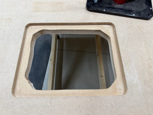
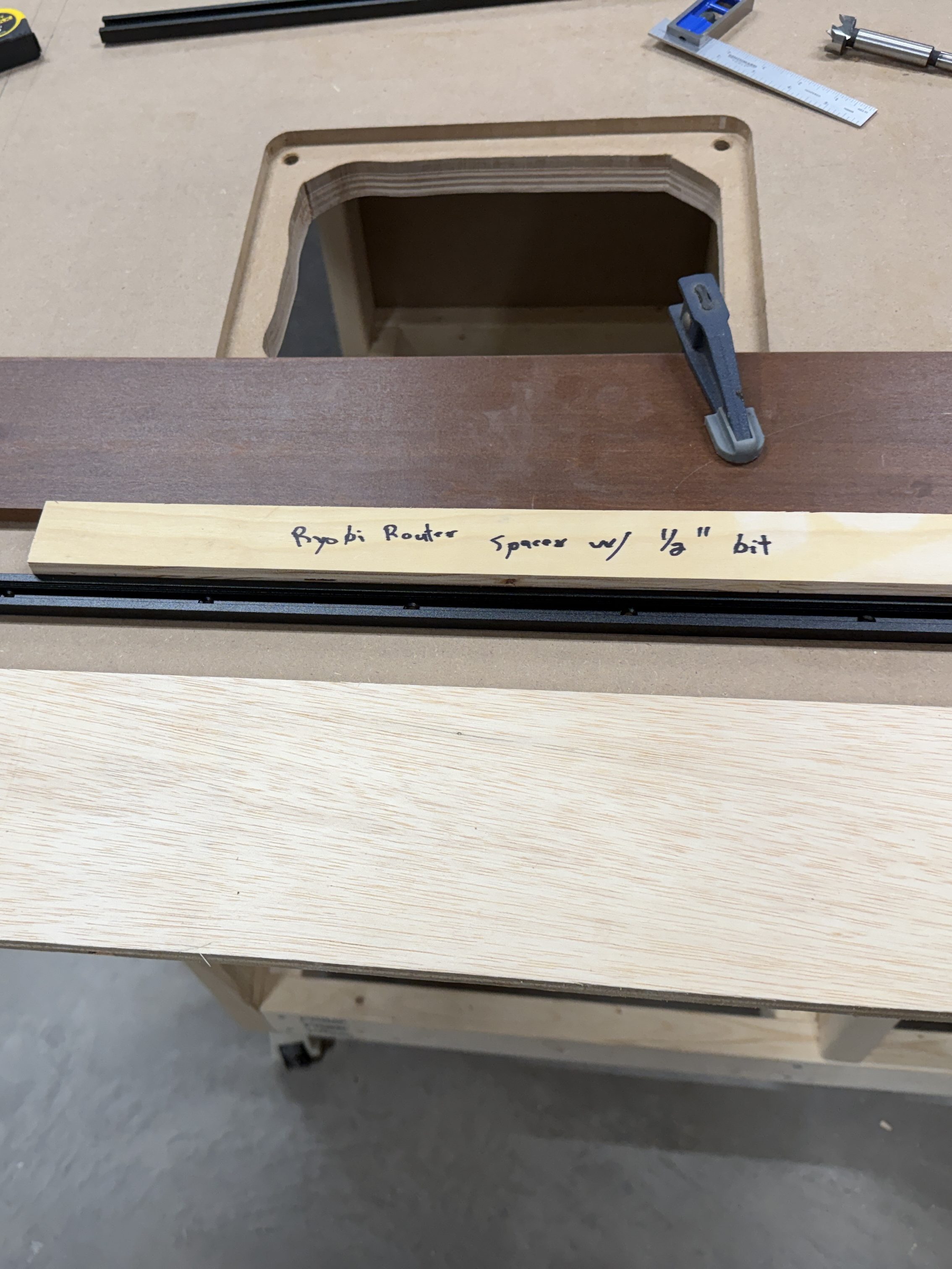
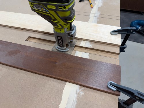
I cut a spacer equal to the distance from my router base to a 3/8″ straight bit. Then I used double-sided tape to secure the border pieces. I removed the material in two passes and cut out the middle with a jig saw. The radius on the corners was much larger than the router bit, so I free-handed those up to the pencil marks.
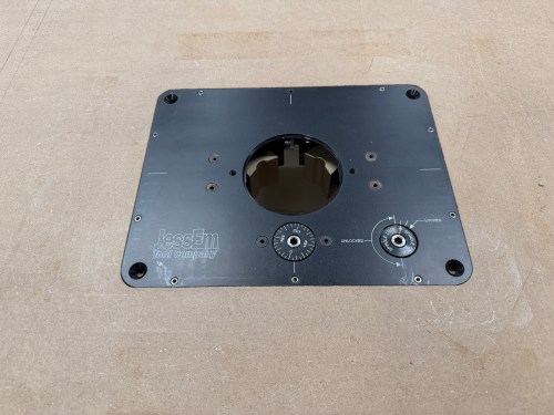
I installed threaded inserts for the four bolts that secure the lift. Yet my centering was off, so it didn’t work out. I removed the inserts and drilled through to use longer bolts with a washer and nut under the table. I had to drill a recess in the bottom because I couldn’t find long enough bolts.
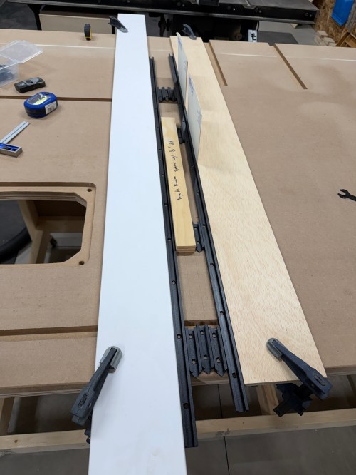
Setting up to route the first T-track took a long time, like when I did the miter slot extensions. I got faster with each one, as I figured out a process and all of the spacing. That same spacer came in handy, as well as pieces of the T-tracks. I measured and cut all of the T-tracks.
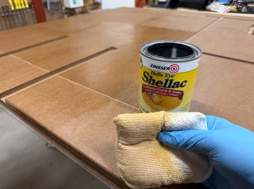
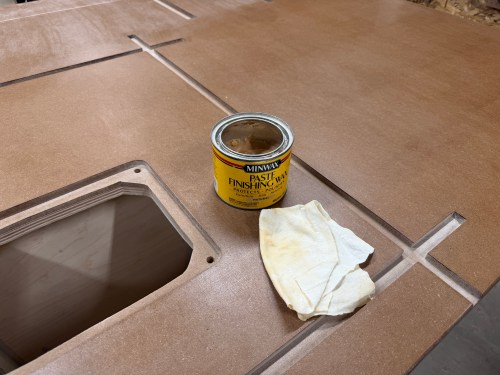
I sanded the top and edges with 80 grit using my random orbital sander .Then I applied four coats of Zinsser Bulls Eye Shellac. A day later I did a light hand sanding with 220 grit and applied paste wax.
A good router table needs dust collection and here are the parts I used for mine:
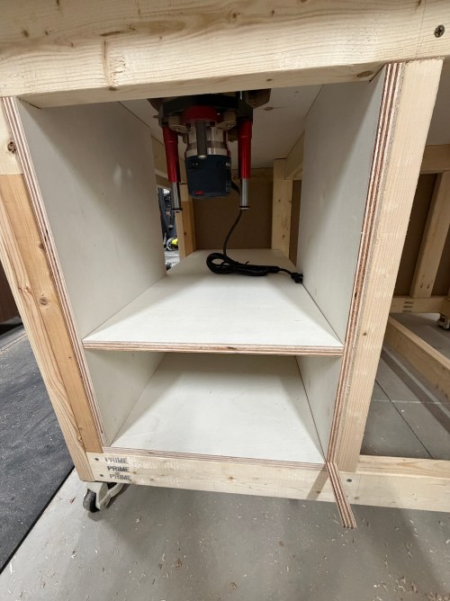
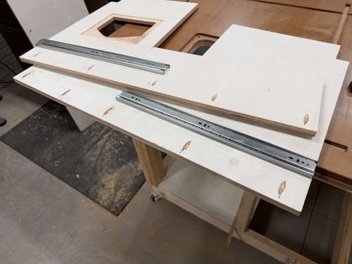
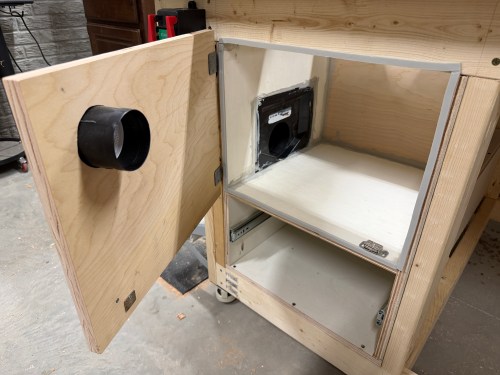
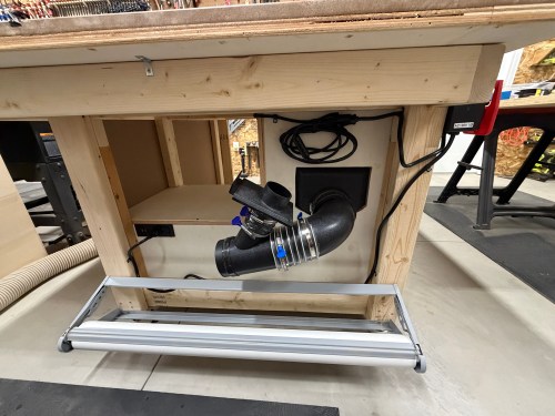
I had to build a cabinet to enclose the router lift, plus a drawer underneath. Due to the table’s frame and a need for the left side, I sketched out a plan. I was making a big version of the L-shaped Tetris piece.
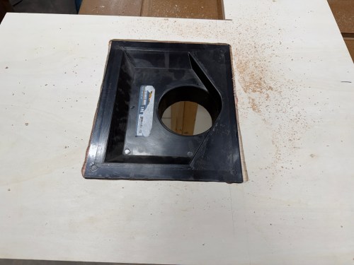
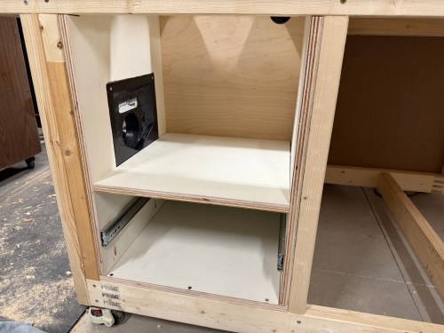
The assembly had to be done inside the frame, due to the cabinet nesting up through the frame. After getting plywood to size, I cut various holes, attached 22″ drawer slides, routed a recess for the dust hood, and drilled pocket holes. It all screwed together quickly.
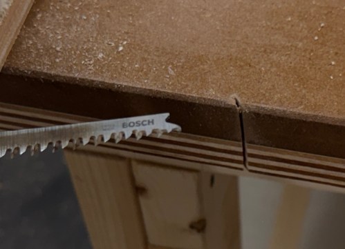
Of course, when using the jig saw, I accidentally cut in to the new table top! I’m the only one who does this, right?
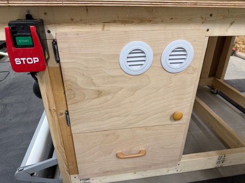
I caulked everywhere inside the dust box. Then I cut a door, mounted hinges, added a magnet close, and used weather stripping to seal it. The door got a hole with a vent cover to supply fresh air to the router and dust collection system. After some use I’ll see if I need to add a second vent. I mounted the lift, leveled it to the table, and bolted it in. The lift doesn’t came with a blank insert, so I bought one from an Etsy store.
Update: I did end up adding a second vent.
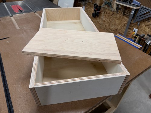
I cut all the pieces for the drawer, cut a rabbet where the bottom would slide in, and drilled pocket holes. Then I glued and screwed it together. Attached a drawer face and mounted a handle.
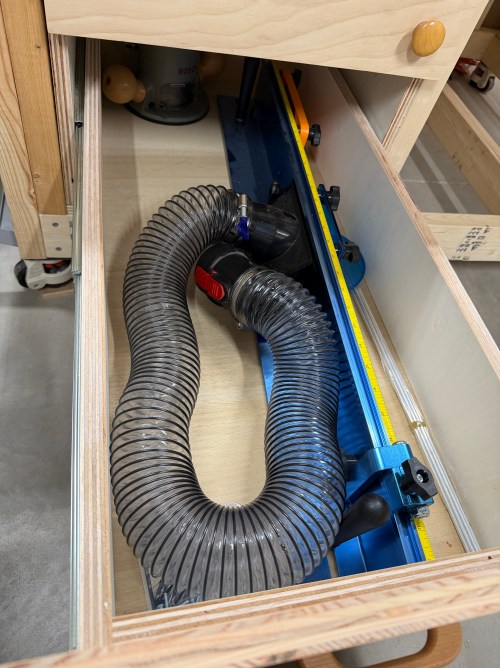
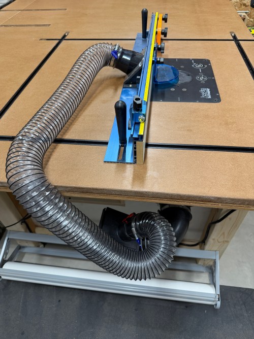
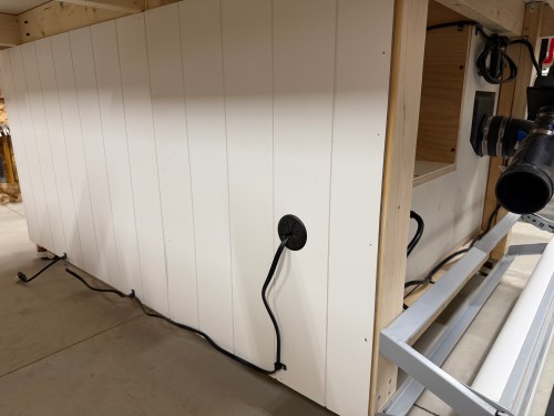
Along the left side of the table, I installed my paper roll dispenser. A 90° and then a Y-fitting connect to the dust hood. A 2.5″ blast gate is attached to the other side of the Y, for a hose up to the fence. The power cord went through a 2″ Desk Grommet on the back side. I screwed a POWERTEC Paddle Switch to the front. These switches makes it quick and easy to turn off the machine with my knee. I put in a recessed power strip with USB ports. Then I clipped in the wires and mounted a heavy duty surge protector power strip. This allows me to plug in the table saw as well.
The final thing was to lower the castor feet to raise the table up to the saw.
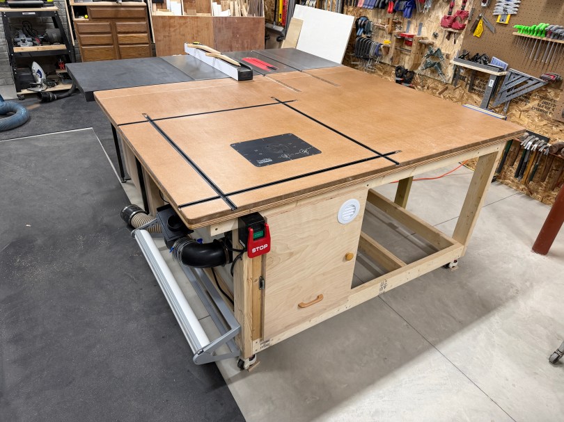
It’s so nice to have a large table table in the shop and I’m excited for the router, where it’s easy to use and always ready. Here are some more pictures.
There are the other accessories I bought for the router station, some of which can also be used at the table saw:
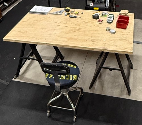
When we moved to the new house, I disassembled my workbench with the plan to build one for the new workshop. More than a year later I was still using the old top on sawhorses and everything I bought for the build was piled up in the corner.
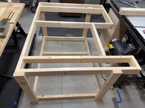
The planning notes and ideas I made last year were a good starting point. I took a bunch of measurements, adjusted to account for the motor when tilting the table saw blade, and mapped it out with blue tape. Made more adjustments, cut all of the pieces from 2x4s, and assembled the frame with 3″ screws. I’ve learned my lesson about not using glue for shop furniture because it’ll likely get taken apart in the future. By only using screws I can reuse the materials when an improved replacement gets made.
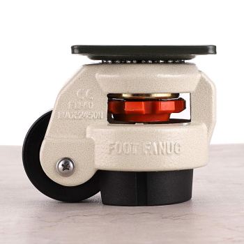
The castors I bought double as adjustment feet, making it easy to raise the height up to the table saw and will make the table stationary 99% of the time.
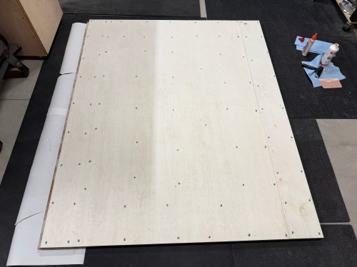
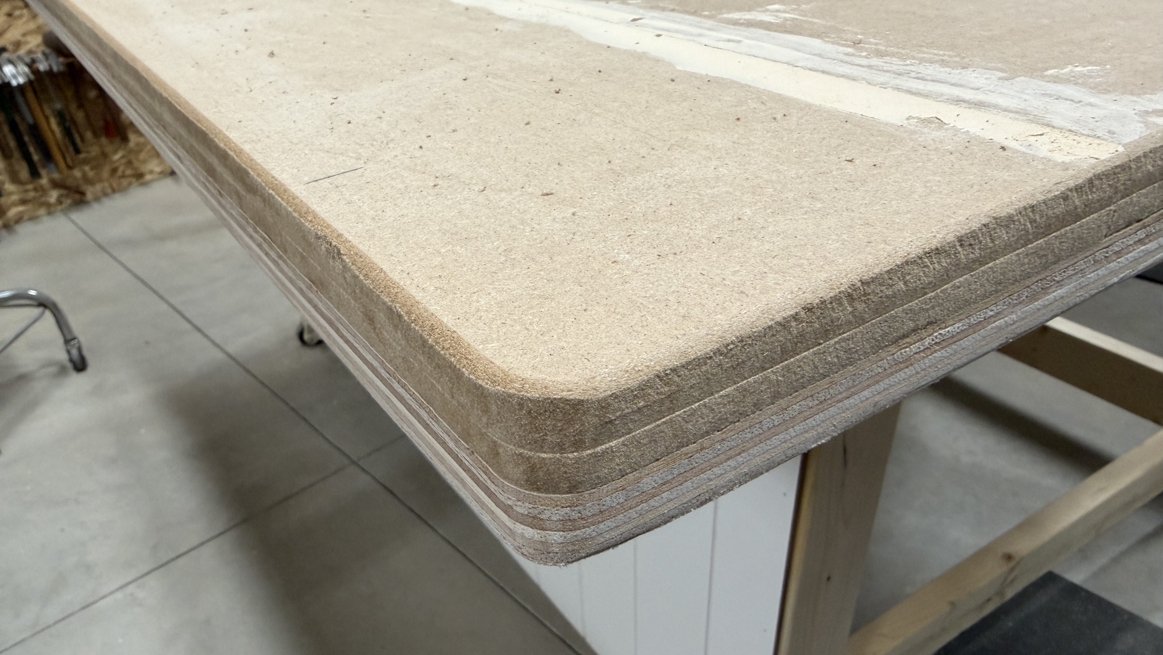
I cut plywood and MDF, then laminated them together, using screws for clamps. Since my top was going to be 66×54″ I had to splice in a six inch strip of each.
After the glue dried I removed all the of screws and got it up on the frame. Then I checked the height of my table compared to the table saw and it was going to work out well. With the blade at 45° and all the way down it was extremely close to the table top though.
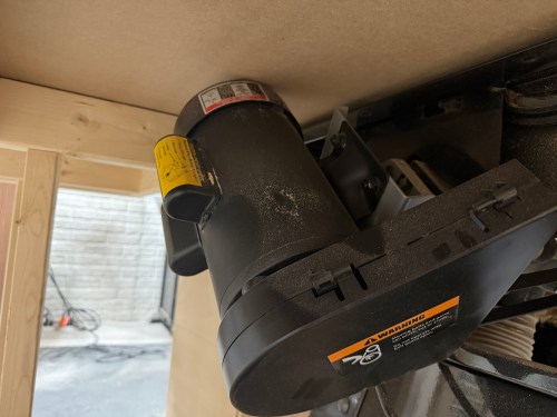
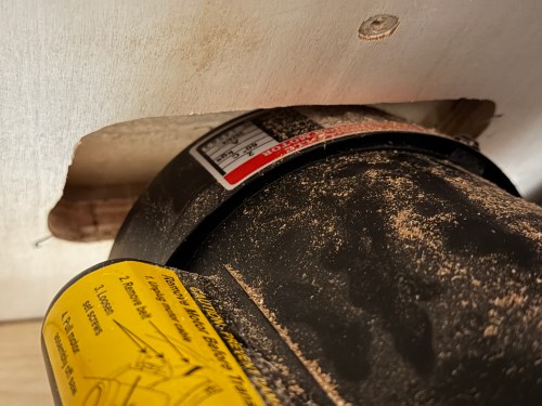
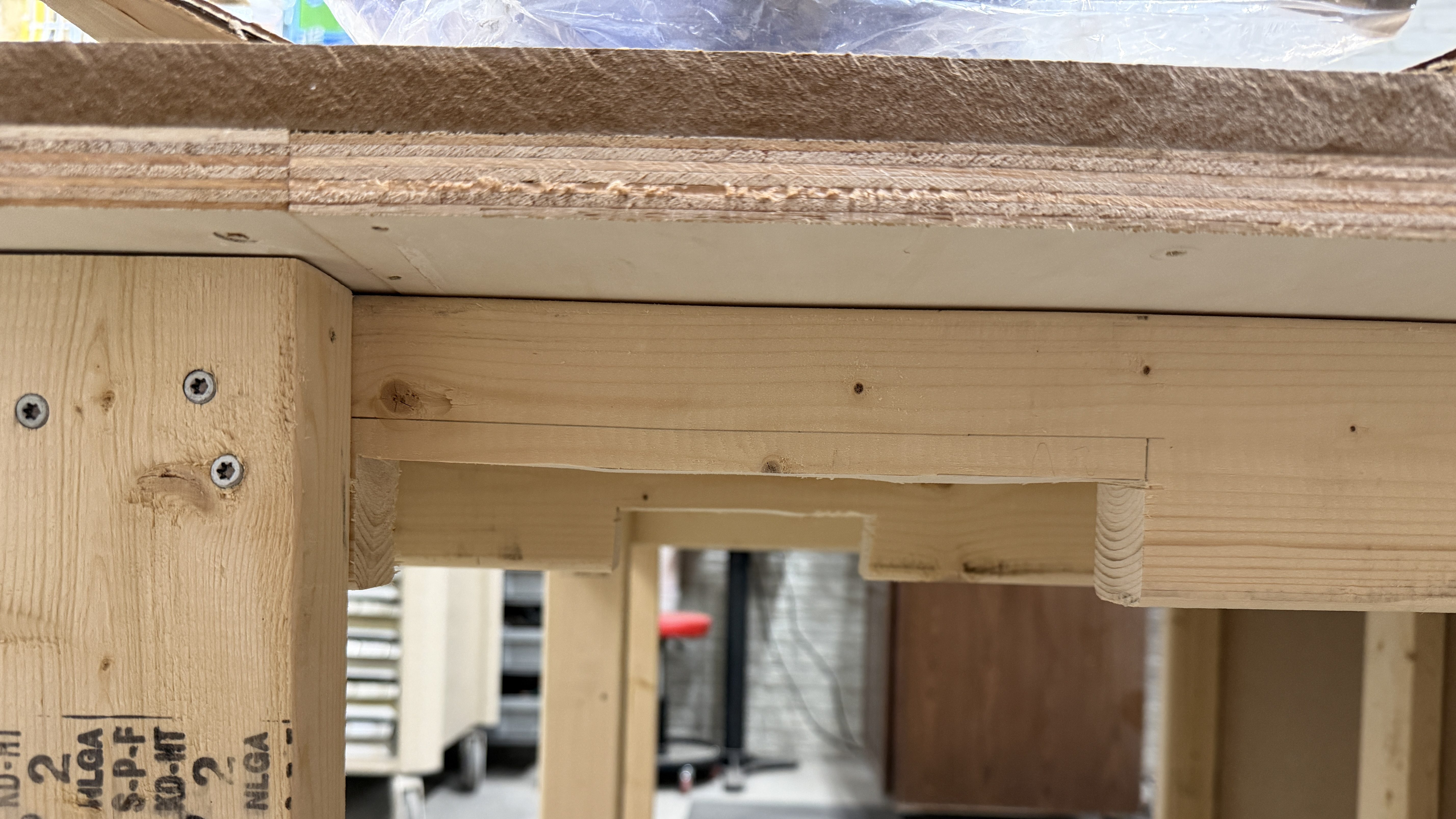
When maxing out the blade height the motor raised about an inch. So I created a clearance pocket with the router.
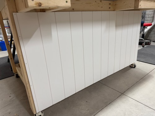
I added a couple more vertical supports along the back of the frame and cut scrap shiplap panelling to rigidify it and close it up.
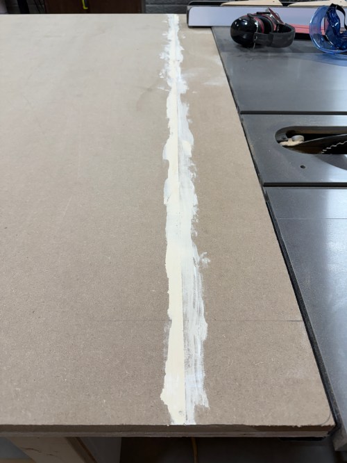
I trimmed all of the edges to size. There was a small gap between the spiced sections of MDF, so I used wood filler.
One inch corner braces with 1/2″ screws were used to attach the top to the frame.
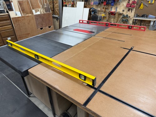
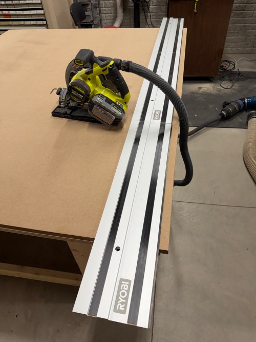
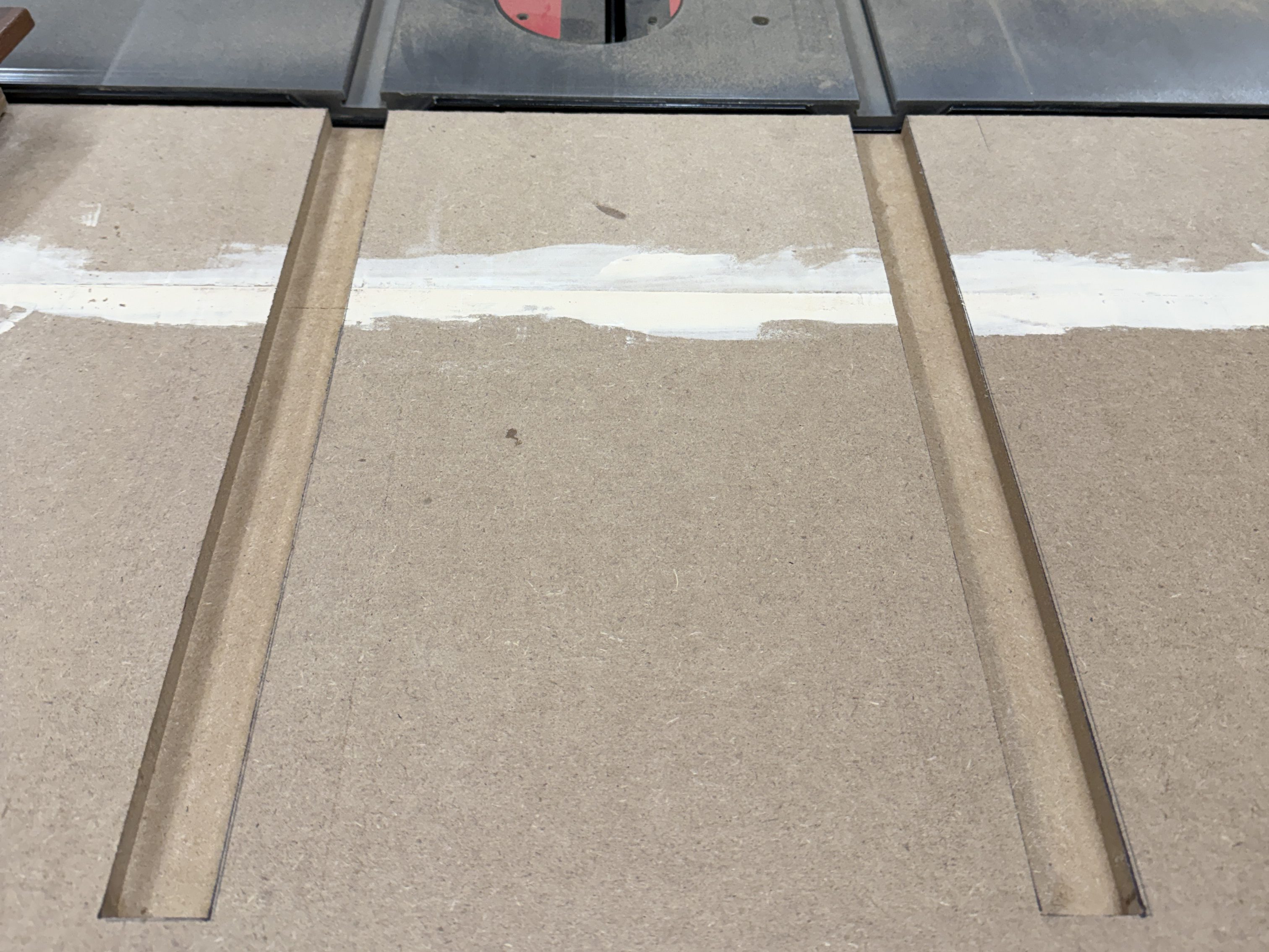
The miter slots were extended from the table saw. I made them wider and slightly deeper, so the outfeed table placement won’t need to be too exact.
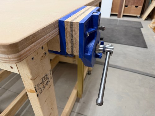
For my vice, I bought a Yost 9″ quick release vice. To mount it I had to remove part of the frame and add blocking.
I realized I should finish up the edges of the table, so I quickly rounded the corners, sanded the edges, and added a roundover.
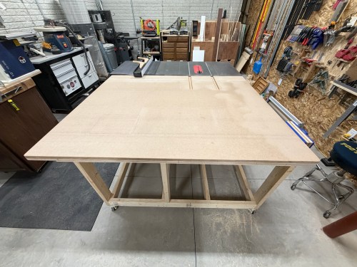
Look at this beauty! So much room for projects and a space underneath for storage.
Continue to Outfeed Assembly Table – Part 2, which is where I add a router station, complete with dust collection. Then Part 3, where I add a bunch of drawers for storage and organization.
An article or ad popped up for this gutter downspout improvement while I was doomscrolling on either Facebook or Instagram and it caught my attention. I’d never even heard of hinges for gutter downspouts, but I quickly I ordered a 4 pack from Amazon. I painted them black to match and the install took about a half hour.
Now when I’m mowing the lawn I can quickly kick up the extension, mow the area, and immediately pull it back down. No more stopping the mower to remove the extension and I don’t have to worry about remembering to put it back on.
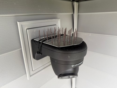
We noticed a robin trying to build a nest on top of our back patio’s security camera. I wasn’t going to let that fly, but after seeing how much is costs to by 20x the amount of bird spike I needed, I made my own. I cut a scrap piece of aluminum, drilled holes in it, added nails, and held them in place with double-sided tape. I wasn’t confident it would hold, so I used zip ties.
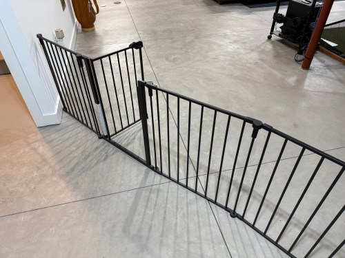
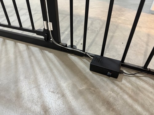
In our basement we have a baby gate, which surprisingly keeps our cat out of the gym and golf sim areas.
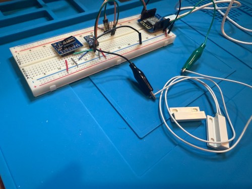
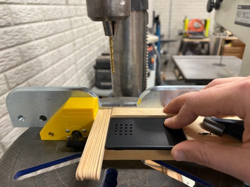
Sometimes we forget to close the gate, so I needed a sensor to monitor its state. I still had the breadboard from the air quality monitor project, so it was quick to add a magnetic door switch and test things out with the D1 Mini clone.
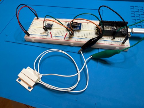
I have extra sensors, so those were kept in the project and allowed me to get rid of the shitty DHT22 I added to the golf remote. Everything worked, but I want to save my last two D1 minis and use them for something with the screens I have for them. So I swapped in an Adafruit Feather HUZZAH ESP8266, which I got with AdaBox 3 or 4 in 2017 and made minor changes to the code.
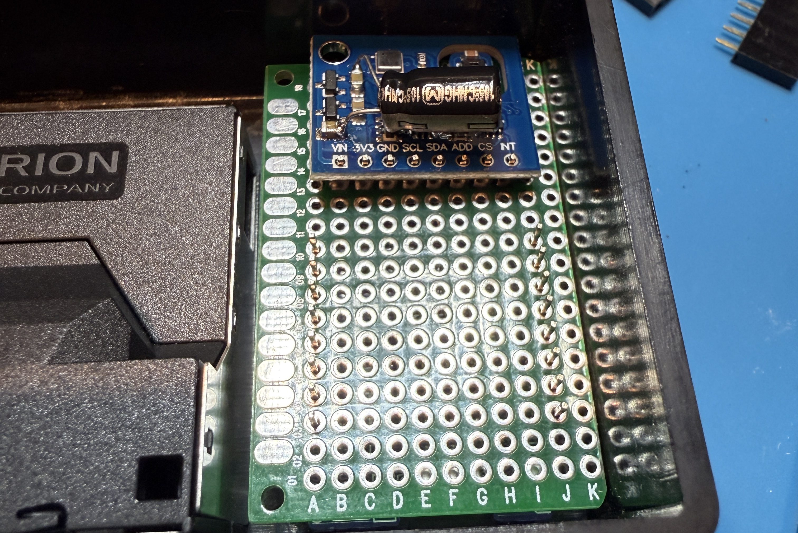
I figured I might as well use one of the fancy Adafruit Perma-Proto boards I had, which makes soldering all of the connections much easier. As a bonus it was nearly a perfect fit for the case.
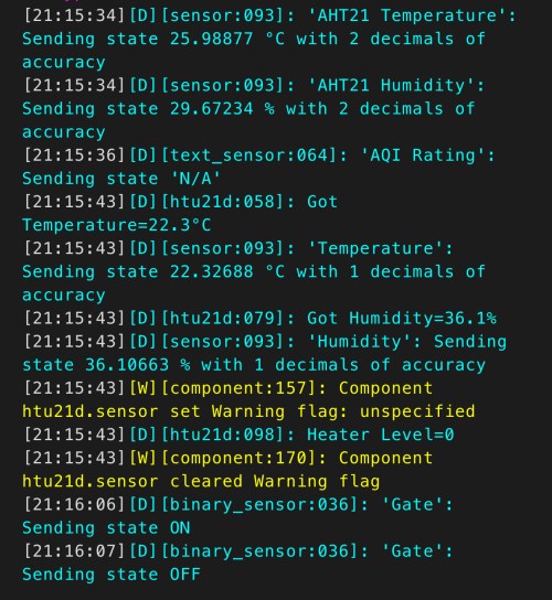
The magnetic switch and Si7021 will live outside the box, so those couldn’t get soldered yet. After connecting power I checked the ESPHome logs to make sure everything was working.
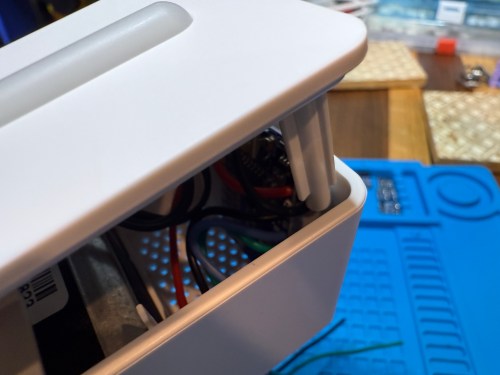
I cut holes in a project box, finished soldering, and used hot glue to secure the board..
I reversed the swing of the gate, placed my device, and attached the two sides of the magnetic switch to the gate.
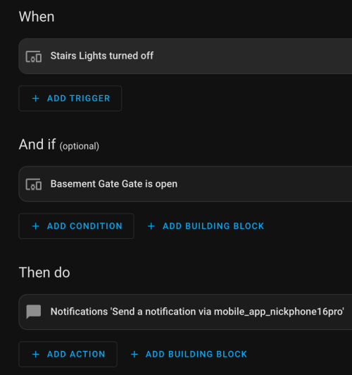
In Home Assistant an automation runs whenever the stairs light is turned off to check the state of the gate. If it’s open, a notification is sent to our phones.
I’m enjoying these little electronics projects, and it feels good to finally put various parts to use.
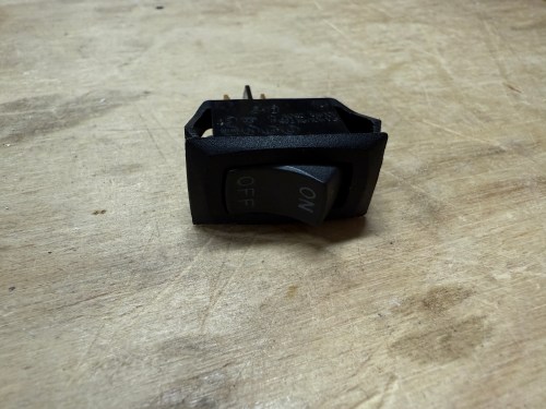
I’ve had this Rigid shop vacuum, from Home Depot, for about 20 years.
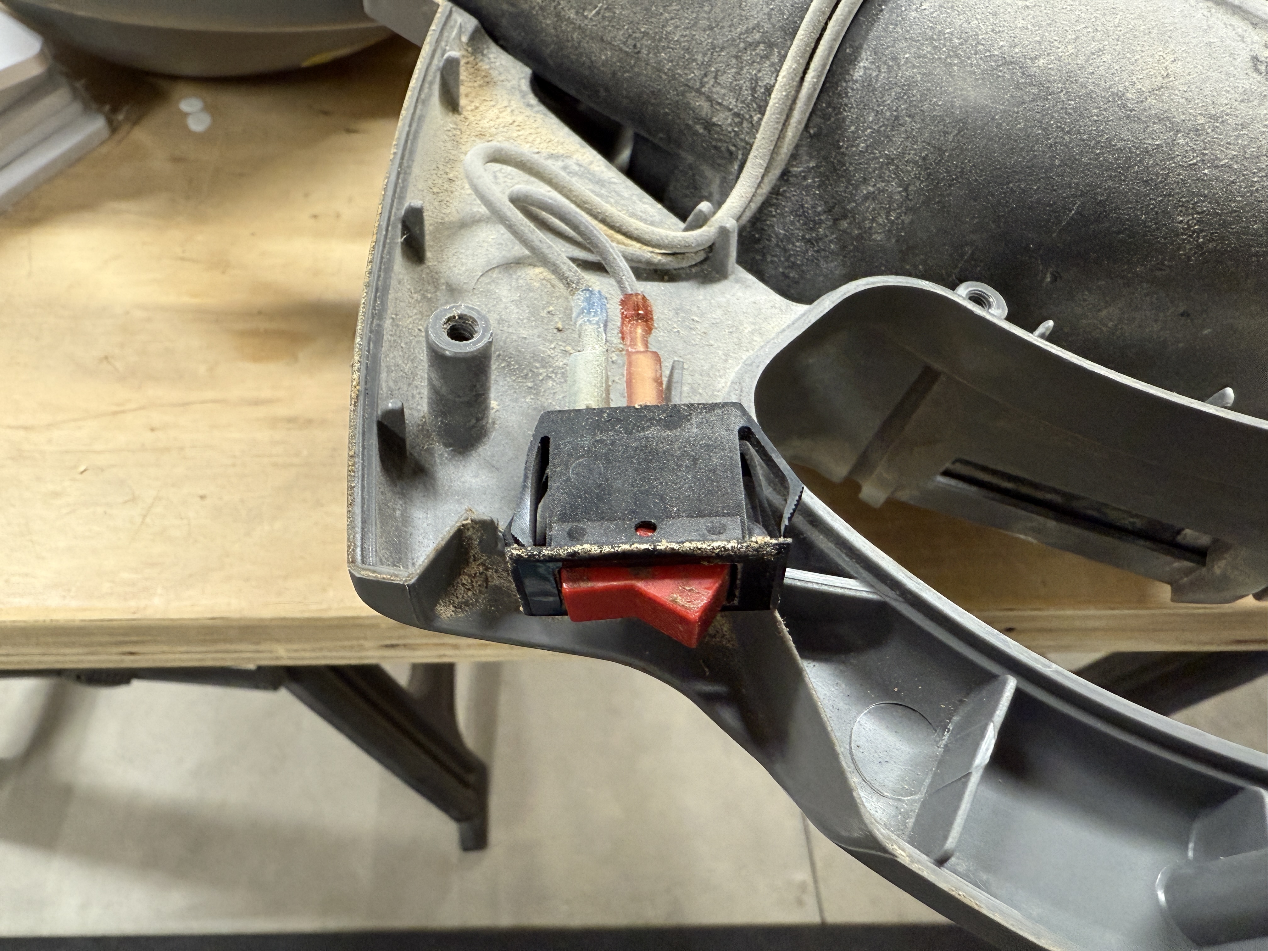
At some point in the last year, the switch started having issues. The vacuum would only turn on if the switch was actually pressed in, instead of toggled. I’ve never seen that happen, but I’m guessing it was from the accumulation of dirt and dust getting inside the switch body. Then the switch wouldn’t even push in, so the vacuum wouldn’t run.
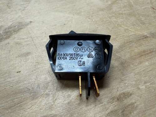
I figured it would be an easy switch replacement, so I removed a bunch of screws to take off the cover. Sure enough, the switch had two wires clipped on to it, and was held in place by the case.
I had a perfect replacement, salvaged from some device I don’t remember, in my collection of electronics parts.
It fit like a glove and the vacuum turned on as if it was brand new. I screwed the case back together and called it done.
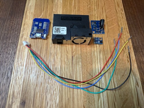
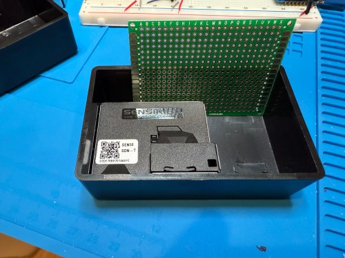
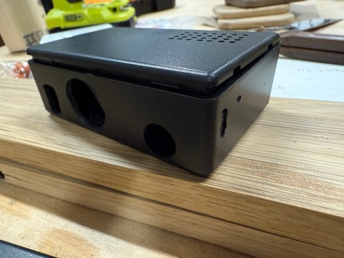
The upgraded IKEA air quality monitors I did work great, but the LED indication isn’t great for a bedroom and the fan noise was annoying in my office. So I wanted to create a couple of my own devices for those locations. I used:
The SEN50 is a big upgrade over the PM sensors used in the IKEA devices and I used the Si7021 in place of the BME280 I had used because I think they’re a bit better. I soldered 47µF electrolytic capacitors from a big kit I’ve had (similar on Amazon) to the ENS150 modules to improve their power.
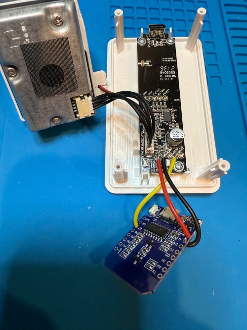
Then I attached 5 of the crimped wires to a 6P JST connector, which is what the SEN50 modules require. I’m note sure why buying the actual cable for these SEN50s are so expensive, but I got the entire JST kit for cheaper than a couple of the special cables.
All three sensors communicate with the microcontroller over I²C, so a breadboard test was easy to wire up. The SEN50 does require 5 volts instead of 3.3, so I’m glad I checked.
The ESPHome YAML code is very similar to the code used for the modified IKEA air quality monitors.
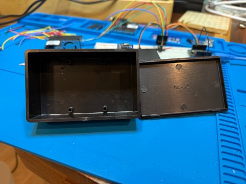
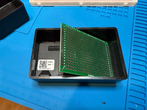
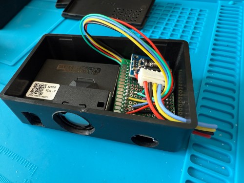
The project boxes had some standoffs on the bottom, which I snipped off and then sanded with a rotary tool. I pulled out my box of proto boards and found a size almost exactly double what I needed, so I cut out a sliver and ended up with a piece for each box. I also cut vent holes for the SEN50 sensors.
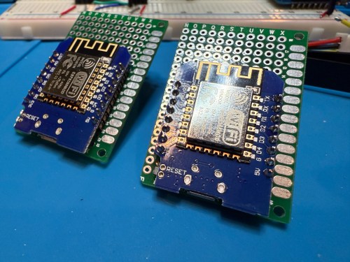
In order to get everything to fit I decided to put the microcontroller on the bottom of the board. After mocking things up I did all of the soldering. I was hoping to be able to mount everything with connectors so it could easily be taken apart, but there wasn’t enough room and I didn’t want bigger boxes.
I did some continuity testing along the way and everything worked when I connected power. With the boards ready I cut more access and ventilation holes in the boxes.
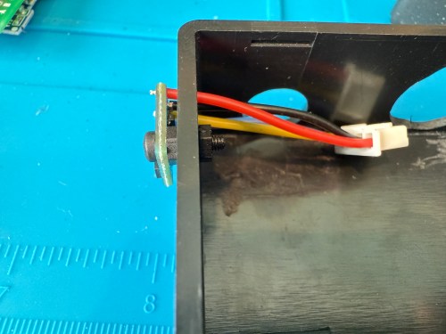
I soldered the Si7021 on to its wires outside of the enclosure so it wouldn’t be exposed to unnecessary heat and used hot gun to secure everything.
I’m really happy with how these turned out. Here’s a view of the office data on my Home Assistant dashboard.
This was definitely a project where I wished I had a 3D printer to design custom boxes. Some day, when I’m caught up on my project list and can give it proper attention. I know if I get one now I’ll spend a ton of time with it and neglect other projects in my pipeline.
IKEA recently discontinued Vindriktning, their older air quality monitor.
Inside the device, they put a cubic PM1006K particle sensor. I bought three for $16.95 each last year, because I’d seen people hack them by adding sensors and a Wi-Fi microcontroller to send all of the data to Home Assistant. For my modding I bought:
The YouTube video linked above is a great guide to follow. I didn’t connect wires to the fan or the light sensor since I had no use for them. I also didn’t stack my sensors because I wanted the BME280 to be outside of the enclosure, where it would be less affected by the heat produced by the ENS160 and D1.
Even with the sensor outside of the case, the BME280 still reads high, because it heats itself up. I actually tested different lengths of wires and placements of the sensor before realizing I was still going to have to adjust the data. An ESPHome filter made the adjustment easy, which I did individually for each unit after comparing to a mobile Ecobee thermostat sensor. This is the code from the unit for my shop.
Here is how I’m displaying the data on one of my Home Assistant dashboards.
As I was working on this project I knew I wanted a couple more air quality monitors around the house, which will be finished soon.
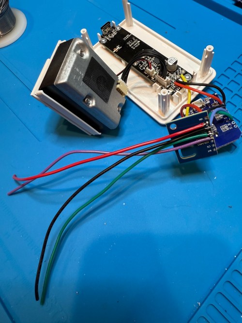
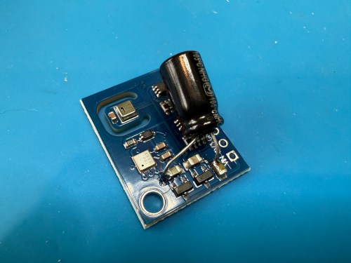
Update: I’ve had to make a small update by adding a 47uF capacitor to each ENS160 board, because they have power issues, causing the reading to stop for periods of time. My boards matched up with the right ones in the picture at that link. Here’s a picture of another ENS160 I modified, since it was a tight squeeze to made the modification on the devices I posted about here with everything already wired up. I also realized I was powering these through the 3V3 pin instead of VIN, so I fixed that.
I’ve also improved the display of the data on my dashboard by using mini-graph-card.