Home Fixes

Yesterday I set out to fix a couple of things around the house.

Garbage Disposal

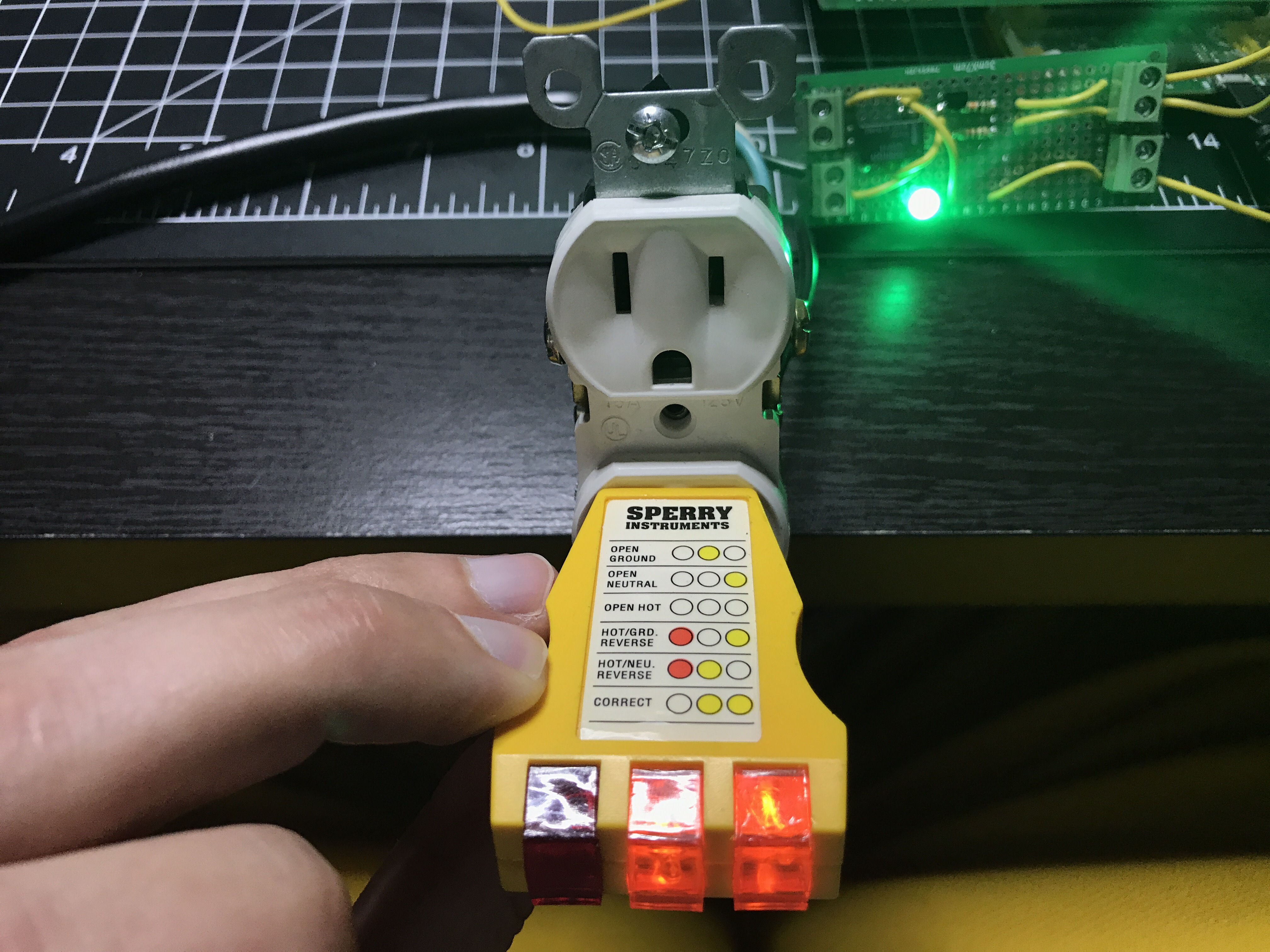
It stopped working several weeks ago when the cleaning lady was using it. I was out golfing at the time so have no idea what happened. There was no sound or anything when the switch was flipped. My first step was to make sure the outlet worked.

test-socket

So then I moved everything out from under the sink, got a bucket to catch the water, and removed the unit. I noticed a red button on the bottom.

disposal-button

It responded like the button on a GFI outlet. Then I plugged the disposal back in. There was a humming sound for a few seconds and then it stopped. The red button had popped out. Must be some kind of safety mechanism so the unit doesn’t burn up the motor. While cleaning out the cupboard I had come across an allen wrench.

disposal-allen-wrench

There was also a hole in the bottom of the disposal where this fit. Gave it a bunch of turns and it started to feel pretty smooth. Pushed in the button, started plugging it in, and holy shit! The torque on that thing nearly sent it flying across the room. Glad I had barely touched the plug to power because my hand was able to jerk it away from the outlet.

I put the garbage disposal back in place, reconnected all the pipes, and I was back in business. No leaks either. Something must have been jammed inside.

As a bonus it turned out to be a good reason to clean the cupboards under the sink, which had accumulated a bunch of junk.

Garage Door Opener Light

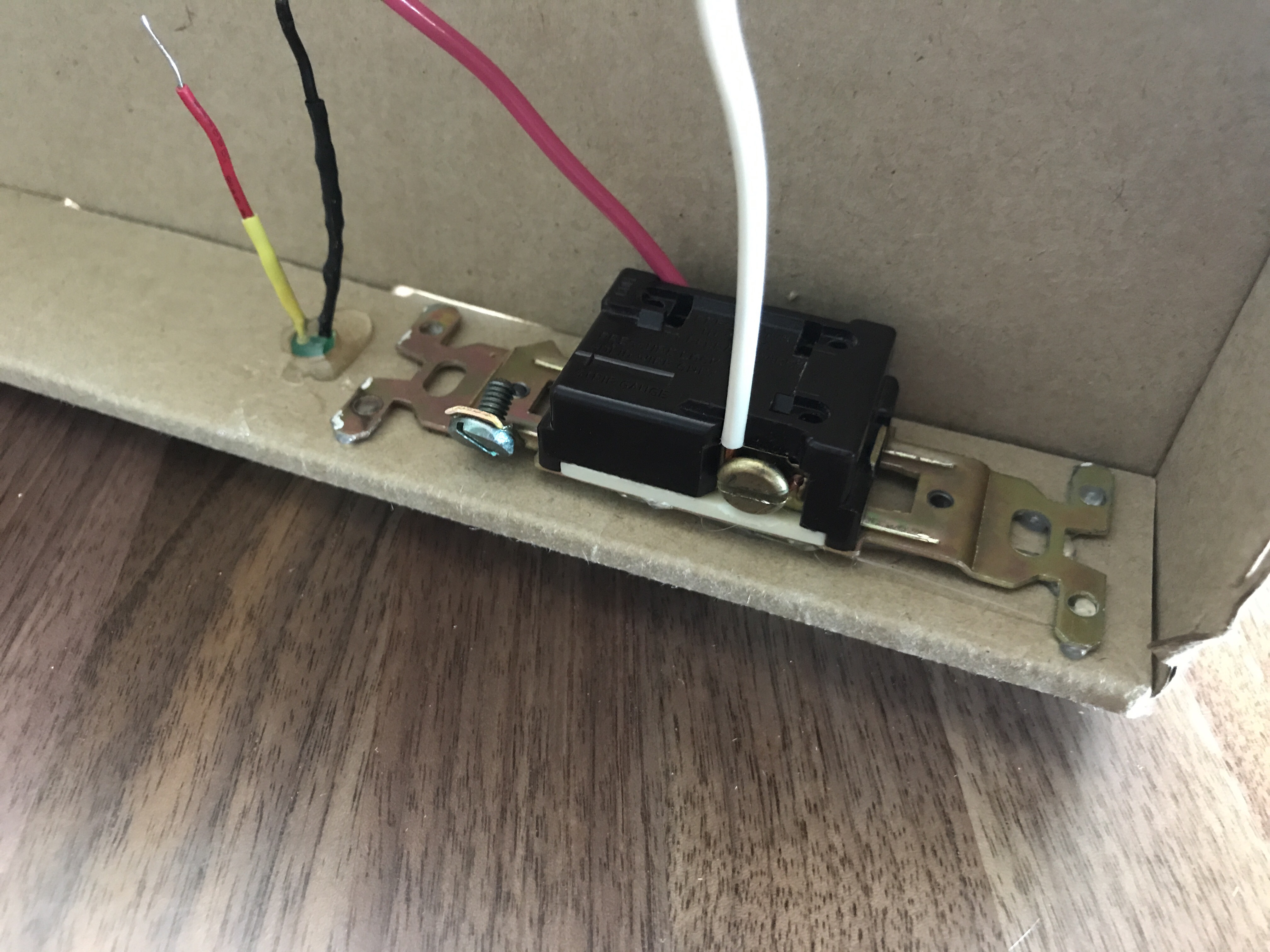
It’s been flaky for several years. I had tried replacing bulbs and sometimes they would work for a bit or flicker here and there, but eventually stop working. With my new knowledge and confidence with electricity and circuits I figured there had to be something going on with the connection. After unplugging the garage door opener, I took off the face plate and disconnected the wires from the back of the light socket.

garage-door-old-light-socket.jpg

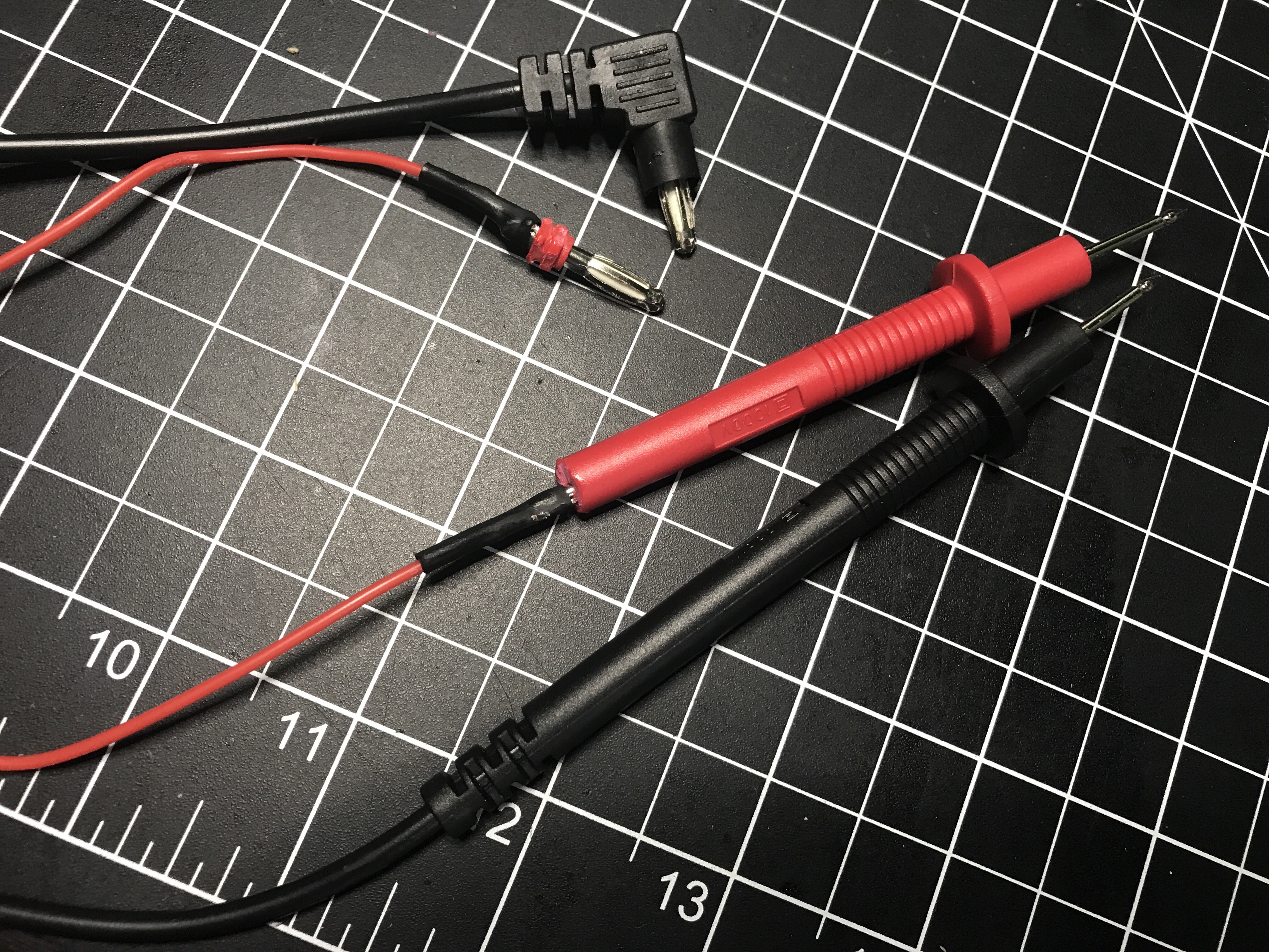
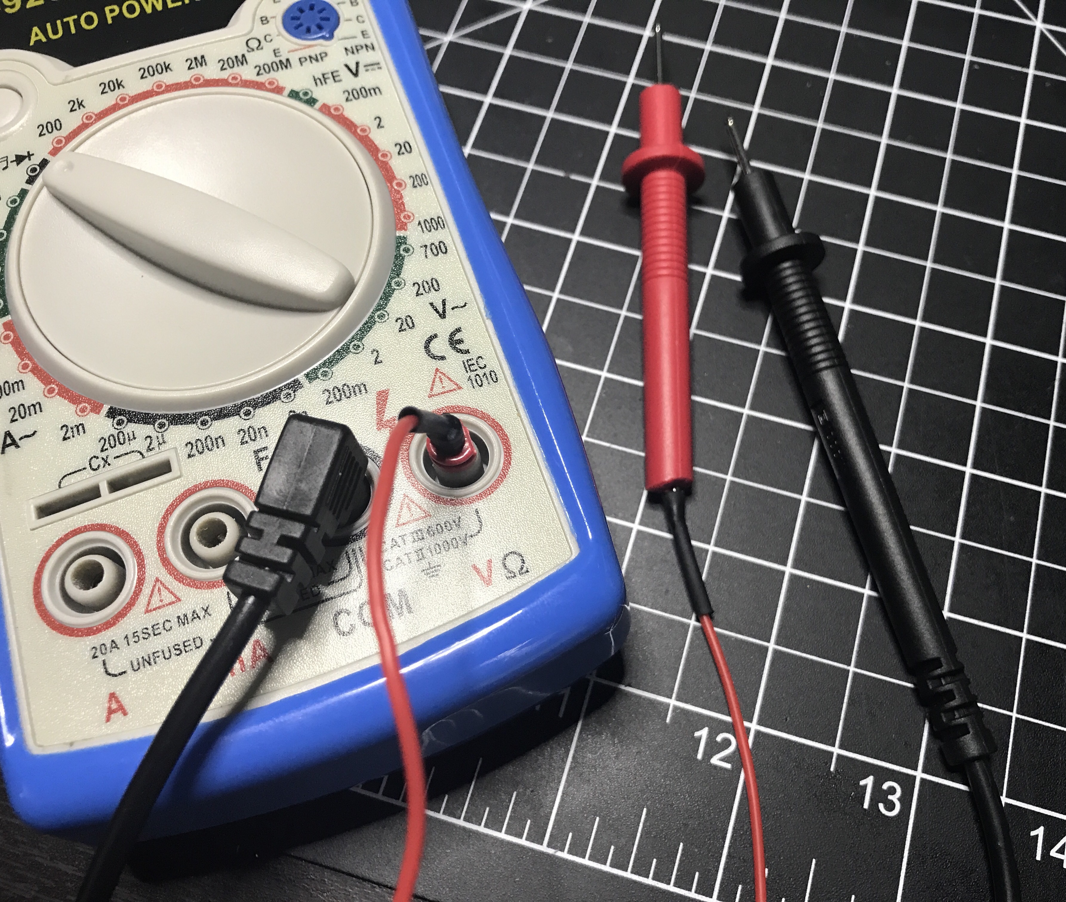
Looking at this socket, 2 things stood out to me: 1) seems like both contact points were corroded and 2) unlike a lot of light bulb sockets where the sides are metal, this only had the contact pad which is at about 1:00 if this were a clock face. I grabbed my favorite tool, the digital multimeter…

I may have been able to clean up the contacts on the socket, but I figured it was better to replace it. The only thing at Home Depot that looked like it would work was this waterproof light socket for $3.47.

waterproof-light-socket.jpg

I carved off some of the rubber with an X-ACTO knife for a better angled fit and applied a bunch of hot glue. Here are views of the front and back…

garage-door-opener-light-socket-frontgarage-door-opener-light-socket-back

It ended up working much better than expected. I reassembled everything, plugged in the garage door opener, and voila!

garage-door-opener-light-on.jpg

I also replaced a 3-way light switch I could hear shorting out, but it was an ordinary replacement job.

5v Relay Module – Part 2

A couple of weeks ago I built a 5v relay module, but realized the relay wasn’t sufficient for my needs. So I had to order a heftier one that could handle more than 0.5 amps of current.

I was under a time crunch and couldn’t wait for a 5 or 10 pack, which had longer shipping times, so I had to go with a set of 2 for $5.99. These are basically the same relays used in all of the manufactured modules you can buy for less than $5, especially if you buy multiple units.

I set up my GoPro overhead and talked through the build process of my new relay module. It was not a smooth process, because I finally messed up my wiring, which I’d been so proud of hitting a 100% success rate on first attempts when putting together circuit boards. I not only messed up, but I realized my mistake, and then fucked it back up after thinking I was right the first time.

I forgot to take any good pictures of the completed relay module this time around, so here is a blurry screenshot I grabbed from the video, showing the original relay module, the non-working version (which I’ll eventually fix up), and my final version. Similar to whenever I screw up and lose a bunch of code, I made it a personal challenge to turn out my best work on the redo. As you can see, my final version saved a lot of space.

relays

Now that I’ve created my own relay modules, I won’t do it again unless I have specific requirements. Buying the same thing already made is a lot more time effective. It was fun and a great learning experience though. Here’s what the wiring diagram looks like spaced out on a breadboard. There isn’t much to it.

fritzing-relay-no-led

You can grab Fritzing files over on GitHub. Two things that helped me out a lot with this build were a video Homemade 5V Single Channel Relay Module Shield For Arduino, PIC, AVR and an article Turn Any Appliance into a Smart Device with an Arduino Controlled Power Outlet. Between finishing my build and writing this post, I also came across Arduino Controlled Power Outlet on Electronics Hub, which is a neat site with a lot of great circuits and tutorials.

There also ended up being a part 3 to this.

Wire Loop Game

Kennedy and I made a wire loop game, using some basic cheap electronics.

  • 9v Battery
  • Buzzer
  • Old light switch
  • LED
  • Various wires
  • Nuts and bolts
  • Electrical tape
  • Wire screw caps
  • Cardboard box

The initial wiring and cutting of the box took more time than I figured and she started to lose interest until we got around to the top. We did this all on-the-fly, but there are plenty of tutorials (like one on Instructables) you can follow.

​​ ​

A Quick Multimeter Fix

The last couple of times I went to use my multimeter, it wouldn’t read voltages or do a continuity test. I didn’t really need it at those times, so I set it aside. Well, I needed it tonight to diagnose something causing problems in a circuit, so it was time to figure out what was wrong.

After unscrewing the back of the multimeter and looking inside, I noticed there were contacts where each of the cables plug in. I got out some alligator clips to use as test leads and the device worked fine. Then I did continuity tests on the cables and the red one failed.

It was time for some surgery so I hacked the ends off. The wire inside was so small and fragile that it had pulled apart from the probe’s end. I cut a new cable using some silicon wire I bought last week since it’s really flexible compared to the wire I use to build circuits. Soldered the ends back on, put some heat shrink tubing over the connections, and I’m back in business!

5V Relay Module – Part 1

You can buy all sorts of 5V relay modules on Amazon for as little as $3-4 (probably even less if you get really cheap). They even sell boards with multiple relays if you need to switch more than one thing. Since I had all of the necessary parts I built my own. Yesterday I finished the board, because I had to do something before National Week of Making ended.

It worked great switching power from a 9V battery, but the real test was hooking it up to mains power. Electricity gets a lot more dangerous at 120V! It was a little scary plugging everything in and flipping the input, especially after reading so many warnings online, but there were no sparks.

Tester shows the wiring is correct.

I need to pick up a plastic outlet box to house everything so it’s safer with the exposed soldered circuit board in there; I don’t know what I was thinking when I bought a metal one. I’ll publish a more detailed post this weekend when it’s complete.

Update: I realized the relay I used in this module can’t handle the amount of current I need, so I ordered a different type of relay and will be making a new module. I’ll take the opportunity to make a more compact design as well. I did shrink this one a bit and cut off some of the board. I’ll save this module in case I ever need it for a project.

Check out Part 2.

A Raspberry Pi HAT

I successfully built the second piece to a large project I’m working on. I’ve essentially built my own XL Raspberry Pi HAT (Hardware Attached on Top). Since I’m not following the specs, I shouldn’t really call it a HAT.

I’m not sure how, but once again I correctly connected everything on the first try. Either I’m extremely lucky, my attention to detail is paying off, or a combination of the two. I’m just waiting for some catastrophic failure to happen soon when I solder things the wrong way one of these days. Every one of my solder bridges worked. I did run continuity tests on all of the early bridges, which I’m sure was a big factor to my success.

Any guesses on what this board does? Leave your best guess in the comments. It’ll be at least a month before I share more details because I need to finish the entire project first.

Fidget Spinners

I made a couple of fidget spinners out of wood, screws, and a couple of 2 cent coins from Spain. The bearings came out of old Rollerblade wheels. Even after cleaning up the bearings, neither one spins very well, so I think I need to get some ones before making more spinners.


This was a good excuse to buy a Dremel, which I’ve been wanting for a long time. Awesome tool to have. I didn’t buy it until I’d already cut out the basic shapes and done some basic sanding though. The next batch of spinners will be much easier with the Dremel available for the entire process.

DIY Farmers Walk/Carry Handles

After tweaking my back and starting a push-only program which has a lot of accessory movements, I’ve been all about unilateral movements. Constantly using the barbell for lifting can create a lot of imbalances. One of the movements we do a lot is a Farmers Carry with kettlebells or dumbbells. Options get limited if you want to go heavier […]

Repurpose

After watching recent Adafruit videos (1, 2, & 3) about IR and getting a neat new microcontroller which has a built-in IR transmitter, it looked fun to hack around with. I don’t have an IR receiver though. Then I remembered this old component video switch was in a storage closet. I tore it apart and easily got out the IR receiver. While […]

DIY Spliced USB Cable

Even better than soldering the ends of a spliced USB cable is tearing apart an old cable to salvage the connectors and soldering your own wires. I only need power so skipped the 2 data wires. Hopefully using my own 22 AWG instead of the cheap stranded wires will be less resistant to a voltage drop as well.