Circuit Breaker Install

My brother had asked me to help him upgrade some wiring for his shop, because he only had one 15 amp circuit powering the entire shop. Running his planer along with a shop vac would trip the breaker. I’d never installed a circuit breaker, but I was up for the challenge. This weekend I finally got some time to make a trip down.

For the new circuit we decided to use a 20 amp breaker in case he gets a machine that requires more juice. We (Mostly him, because crawling around in the hot attic was all on him.) ran 12/2 Romex wire through the attic and across the porch roof. Then we did a bunch of outlet rewiring to swap two 15 amp outlets with 20 amp ones connected to our new circuit. We also added a new 15 amp outlet from this circuit on the outside of the shop where they could plug in their patio string lights.

We saved the scary part of installing the new breaker for last, which might have actually been the easiest part of the job. The inside of that box is still extremely dangerous when MAIN is turned off, so I just had to be careful not to touch the wrong things (or die). After closing up the box and flipping the switches everything worked as planned!

DIY Custom Michigan Rummy Board

Our family always had fun playing our own version of Michigan Rummy (there is also a version called Tripoly) as kids. Then last year we played it almost every night on our family vacation, using a modified board. It gave me an idea to build a custom board for my Mom.

img_1210.jpg

As soon as I saw this case with two decks of cards at an estate sale several months ago I knew it would be neat for the board. I think I paid $1. The copyright date is 1947!

img_1157

I’ve been wanting to build something with pallet wood and thought it would give the board a neat look. You can get free pallets all over by looking on Facebook Marketplace or Craigslist.

img_1137

With the help of my pallet buster and some brute force, I broke down the pallets.

img_1154

These containers with covers are from Menard’s, free after rebate. Another perfect piece for the project. I laid everything out to get a feel for the size.

img_1155

After taking measurements, I mocked up a 3D model of the board’s top layer in SketchUp (download on GitHub). It would be about 24×16 inches.

mi-rummy-model

I also printed out the text using Arial Black for the letters/numbers and Futura for the suit symbols.

Screen Shot 2018-07-04 at 10.41.01 PM

I trimmed, planed, and jointed a bunch of boards.

img_1158

Then glued up panels that would make the top and bottom of the board.

img_1159

I measured and marked a bunch of lines and then placed everything where it would end up to get a better feel for the size and layout. I liked it.

img_1160

I finished drawing in more details and did a rough cut of the outer shape with my band saw.

img_1161

The scroll saw got heavy use cutting everything out. I also cleaned up the holes and edges with various sandering. You can see a couple of places where I started to carve in the text. It didn’t take long to scrap that plan though; it was going to take forever and some of the wood was really soft so I wasn’t happy with how it would turn out.

img_1165

I decided to use raised letters that I’d glue on. After doing a bunch of work, I realized this would be much better because the containers would be up above the board, so it would have been hard to see the recessed lettering.

I used the band saw to cut all of the letters. More sanding to clean them up and then some spray paint.

img_1167

I didn’t get any pictures of the next steps, which probably took the longest. I used a bunch of the cutoffs to build up an outer support ring as well as eight stacks in the middle to prevent something heavy from breaking the top or bottom panel. There was a lot of gluing, clamping, and band saw trimming. Finally I had enough layers and I was able to glue on the bottom panel.

img_1197

After the glue dried I did a lot of sanding on every surface. I had tied in a piece of bungie cord earlier that would hold the card case in place. Then I drilled shallow holes so I could glue in (with epoxy) rare Earth magnets to hold the containers in place. I used CA glue to attach all of the lettering.

img_1201

It was finally time for some finish. I used three coats of shellac (with light sanding after each coat) and a coat of wax polish. I spray painted the Michigan map on half of the containers and gave them two clear coats. The last thing was to stick some of those felt pad circles to the bottom and it was done. I really like how this turned out.

img_1210.jpg

The layering you can see from the sides is a neat look.

DIY Dust Collector Chute for a Craftsman 351.233831 Planer

My Dad got an old Craftsman 351.233831 Planer (manual) from one of his friends for $75 after it stopped working.

When turning it on the motor would hum for a second and then the breaker (or power strip) would trip. He left the machine with me to fix. The motor shaft wouldn’t turn at all so I had to take a bunch of the machine apart (and cut the belt off) to get the motor out. I ended up using a screwdriver and hammer against the fan to free up the motor. It didn’t want to move, but slowly some hardened gunk broke up and the shaft was spinning. Since I had it in pieces I cleaned out the gear box and applied new grease to the gears.

That’s not what the title of this post is about. Since I had the machine I thought it would be nice to build some dust collection for it; these machines create one hell of a mess. Here’s a step by step of the dust collection build.


img_0897
Murdered Out!

I think it turned out pretty good and the paint is a nice touch. I might have to paint the one on my Delta dust collector.

After putting the new belt on and testing it out I noticed the feed rollers were in really bad shape so ordered a new set. The machine is an absolute beast, so I mounted it on one of the Harbor Freight stands, made a plywood base for the bottom, and put on some castors.

craftsman-planer-stand-wheels.jpeg

I still need to figure out how to replace the feed rollers and will swap out some of the knives that are nicked up. Then it should be running like a brand new planer! It’s cool to see my Dad getting excited about a new hobby; he already has a bunch of pallets collected to tear apart.

DIY Overhead Camera Rig v2

Last year I made an overhead camera rig and wasn’t in love with it. It was hard to adjust and unless I was doing a really close shot, the base of the rig was always in the video frame.

When I saw an old swing arm desk lamp at an estate sale I knew I could make something better. Here it is…

It was a very simple build…

Without the base, I’m already in love with how much extra space I have on the desk and how I can move the clamp all the way to the back of the desk with the arm against the wall.

Lamp Repair: Replace Touch Control with a Switch

My Mom’s bedroom lamp was malfunctioning so I told her to send it down with my Dad and I’d take a look at it.

The lamp uses a very common TA-306A touch control unit and the BT134 thyristor on the board often gets fried. I think this might have been my bedroom lamp when I lived with my parents 20 years ago, so there is no sense buying parts for it. I replaced the touch controls with a switch I salvaged from a different lamp.

Replace Fluorescent Tubes in a Light with LED Bulbs

A few months ago I helped my brother rewire some lights for his shop to use LED bulbs instead of flourescent tubes. I decided to do the same thing for my kitchen light, which had been flickering and didn’t always light up every tube.

Years ago, a friend rhetorically asked me, “Are you an electrician?” after I screwed up some wiring, which left us without heat on the coldest night of the winter. I’d say I’m the perfect man for this job. 😉

Jokes aside, it is an extremely easy wiring task. Electrical stuff can be scary for a lot of people, so I figured I’d document my process. Fair warning… I am not a professional and I’m not telling you how to do this. This is just an explanation of what I did. I’m also not a lawyer.

I did this at night, guided by some battery-powered LED lights, so the lighting in the photos isn’t very good.

First I TURN OFF THE BREAKER connected to my light. Absolutely no shortcuts here. Then I took the tubes out and removed the fixture covers.

img_0808.jpg

Those black boxes are the ballasts, which limit the current in a circuit. To use LED bulbs those need to be bypassed. I cut all of the wires and removed them.

img_0809.jpg

img_0810.jpg

Then I stripped the ends of every wire I had cut.

img_0811.jpg

In these particular fixtures, one side used 2 blue and 2 red wires and the other side used 2 yellow wires. The yellow side did use some short white wires to connect one tube to the other, but those white wires were not directly connected to the ballast.

This is the key step. All of the wires on one side of the fixture needed to be connected and then connected to either the black (hot) or white (neutral). It doesn’t matter which side goes to white and which goes to black, but it’s very important that everything on one side of the fixture goes together.

As you can see here I grouped by dark (blue and red to black) and light (yellow to white) colors. I screwed a wire nut on each bundle of wires. When I have 3 or more wires connected like this I gently pull on each wire to make sure nothing will come loose.

img_0812.jpg

Before I closed everything up, I flipped the breaker and made sure the light switch was on. Then I took one LED bulb and tested it in each spot to make sure everything worked. There’s nothing worse than having to take something apart after it’s been closed up. Everything worked great, so I wrapped each wire nut with electrical tape.

img_0813.jpg

For the final step I put the covers back on over the wiring and slipped in the LEDs.

img_0814.jpg

It made a huge difference in my kitchen. Here are some unedited before and after shots.

img_0818.jpg
The camera really shows how green the light was from the flourescent tubes.
img_0819.jpg
You can see how much more natural the wood looks.

What happened with that wiring mistake I made years ago? We got drunk and survived a cold night. I woke up early the next morning determined to figure out what I had done wrong. I fixed the mistake and learned not to assume that speaker wire running through a basement ceiling was useless. I’m probably lucky the wires I cut were only used for thermostats instead of something with a higher voltage.

I didn’t let my friend’s joke discourage me from trying. To this day I continue to learn.

Delta TP305 Planer Dust/Chip Collection

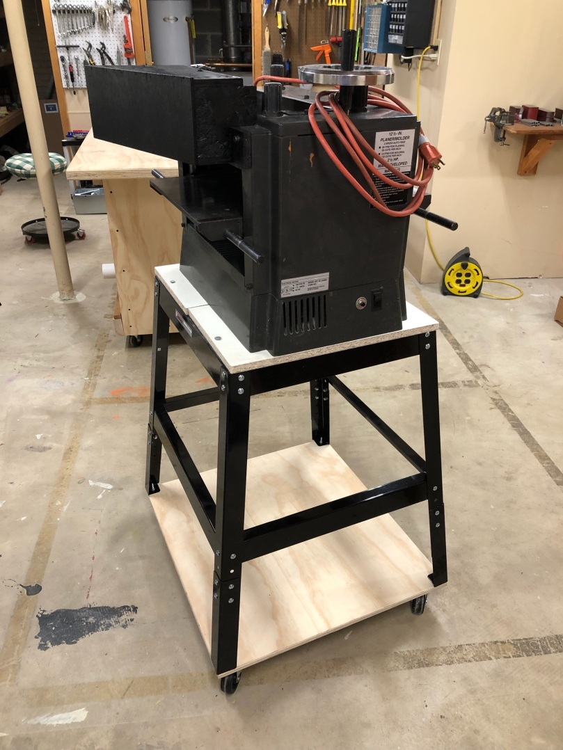
Back in early November I found this Delta TP305 planer for $100 on craigslist.

It was obvious the owner took care of his tools, he had just replaced the blades, and also had a set of new blades, so the price was a steal. It didn’t have any type of dust/chip collection though.

delta-planer-dust-chute
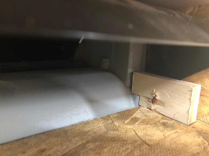
When Delta produced this planer, the dust collection attachment was an extra accessory. I decided to make my own because I don’t understand this design. Why would you want your hose hanging over the outfeed? Too much risk of the work piece getting jammed on the way out, which is extremely dangerous.

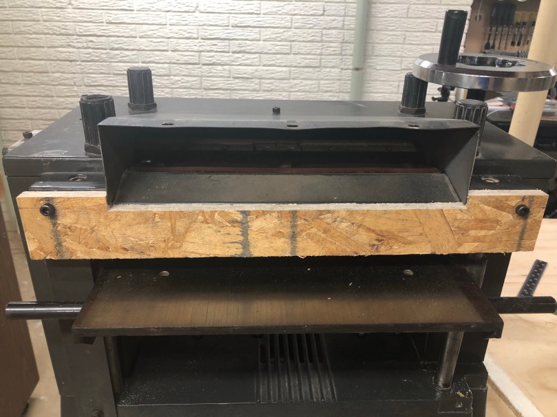
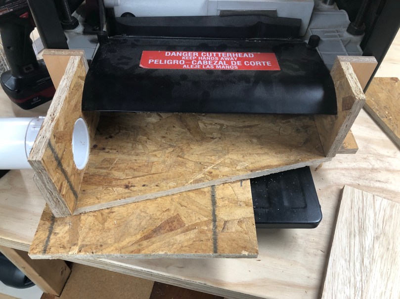
I found a neat idea on YouTube and went with a similar plan. Here is what the outfeed looks like normally.

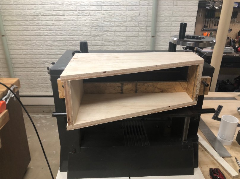
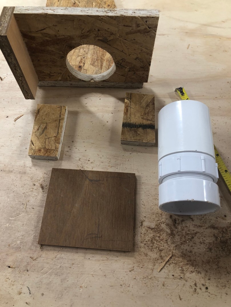
I first cut some pieces to make the sides and bottom of a box.

img_0706.jpg

I screwed the right side together. Then I held it up against the planer to get the exact positioning before screwing in the left side. I wanted a snug fit.

img_0708.jpg

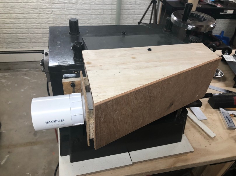
I cut and sanded a hole in the side for some PVC parts.

Grabbed a few scraps that would be used to hold the PVC in place.

Cut a hole in the thin piece, boxed in the male PVC part, and screw it all together.

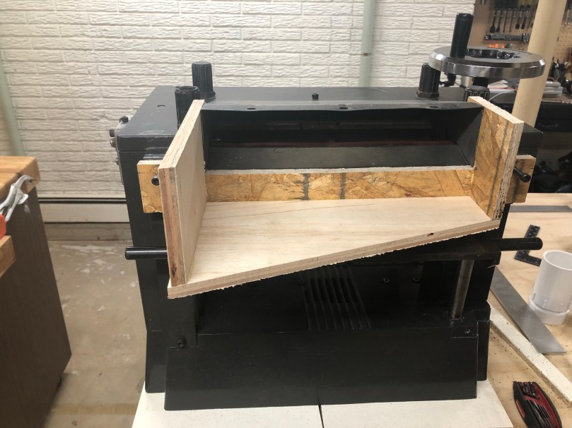
Then I put a spacer under my in-progress box and adjusted the planer’s height. It was important to use a spacer for these next steps because I don’t want the bottom of the box to have any chance of jamming up the wood coming out of the planer. I gave it about 1/8″ of breathing room.

I cut a piece for the top. Then while putting pressure on the edge that makes contact with the planer dust chute I screwed this piece to the sides. At this point I was able to remove the spacer because the tight fit was able to hold the box in place.

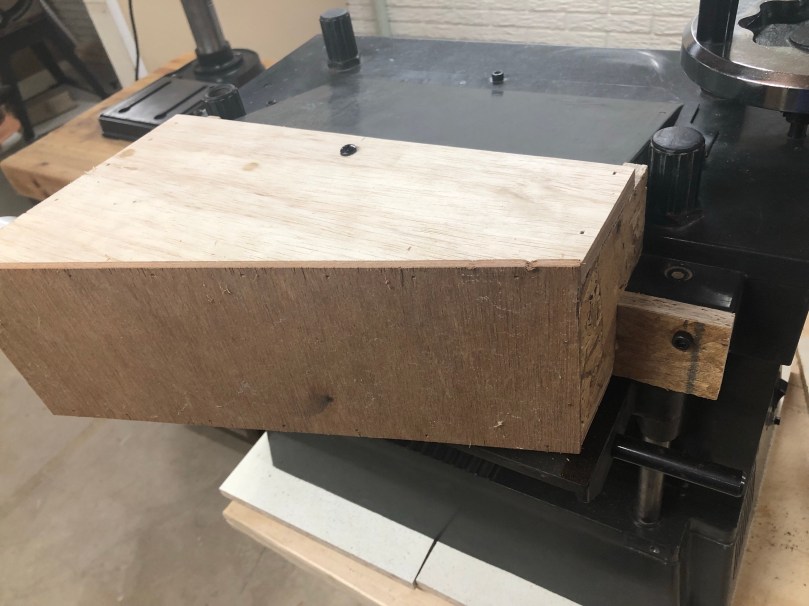
I wanted to prevent the box from sagging or shifting down during use though. So I cut two little pieces.

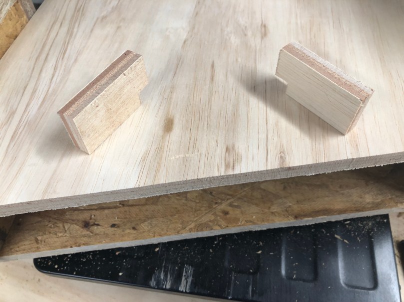
Screwed them in from the bottom on each side.  Notice how the kind of grab on to some ledges of the planer. This is a simple way to prevent the bottom of the box from going any lower.

I drilled a hole in the top and through the metal chute. Combined with the tight fit and those blocks, now this thing can only shift up and away from the outfeed path.

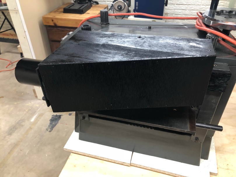
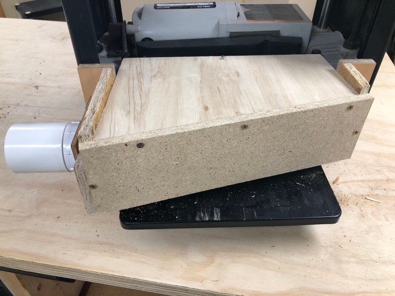
The final step was to square up the back edges, cut a piece, and screw it in. There are no screws on the bottom of the back face because I used a scrap piece that wasn’t tall enough to have room for screws there. I did use some glue though.

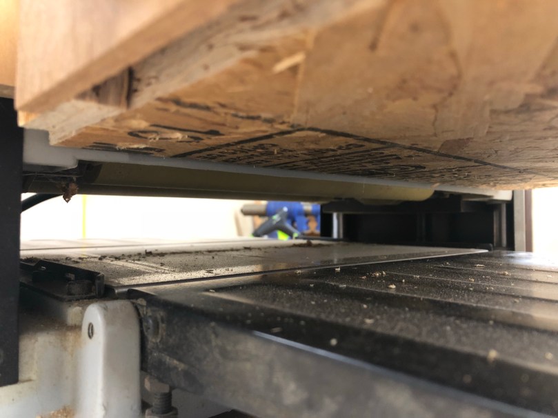
Here you can see the clearance between the box and the outfeed I mentioned earlier.

Due to the materials I skipped using any wood glue except when I put the back face on. I did go back and hot glue all of the joints so it would be sealed for a better vacuum.

This was an easy build. The only modification to the planer was the screw hole and the whole unit can be removed by taking out that screw.

How well does it work though? You be the judge…