I’ll likely turn this into something that interfaces with my Home Assistant server to control different devices around my house.
The PyPortal has been sitting on a shelf ever since. Way back in February, it caught my eye, and I picked it up, not remembering what it’s capabilities were. Then I started upgrading IKEA air quality monitors and even made my own. Since I’m at the desk in my office a large portion of the week I thought I would make that 2019 prediction come true.
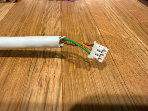
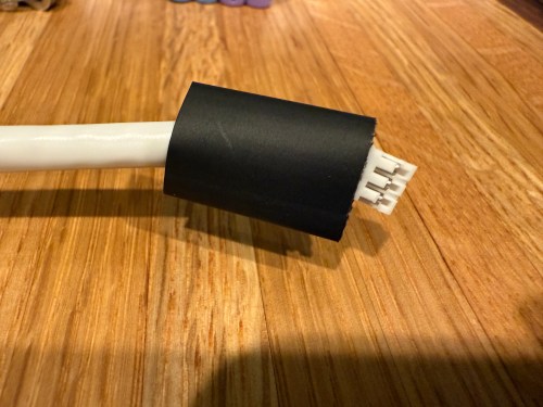
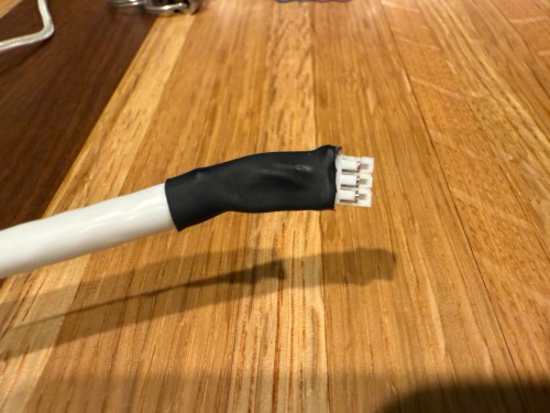
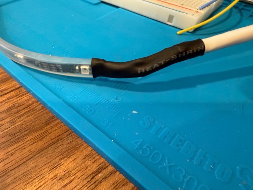
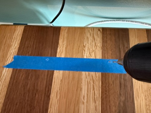
I could show a bunch of data on the screen and the PyPortal has a touchscreen, so I could display buttons for triggering things around the house. The device also has connectors for doing GPIO, so I got the idea of adding an LED strip, which I could use for notifications. I even had a meter long strip of Adafruit Mini Skinny NeoPixels I had bought in 2017 and never touched that would be perfect. I needed to buy a 2.0mm JST PH Connector kit in order to make a wire that would connect to the pack of the PyPortal. I ended up using a piece of Cat6 cable, even though I only needed 3 of the 8 wires inside.
All of this was done back in March. I quickly began having issues with the ethernet cable and the small JST connectors, so I put this post on pause. Figured it was time to finally fix this before the end of the year. While testing, I determined the LED strip got fried up at some point. It was probably some kind of short from the janky wire.
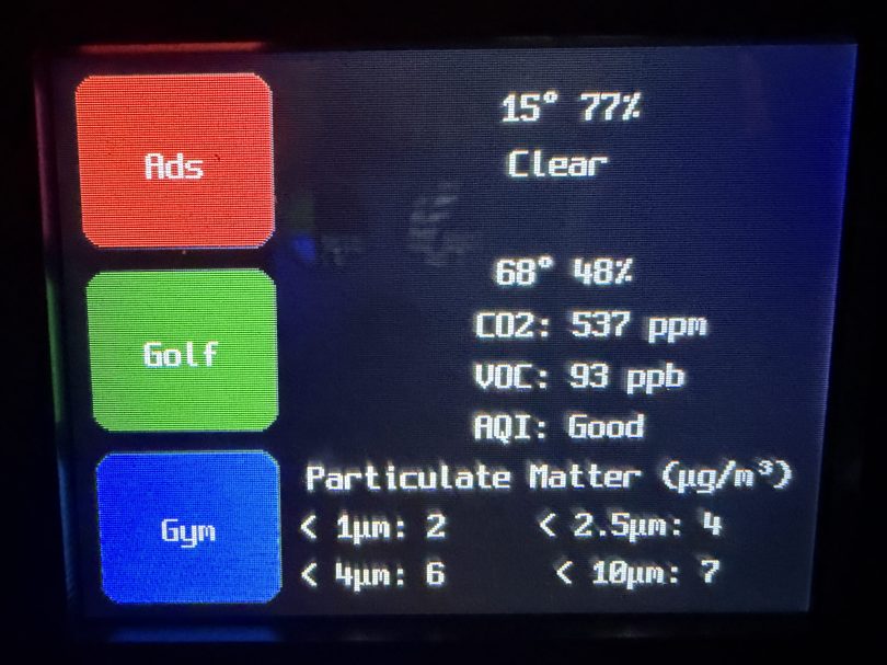
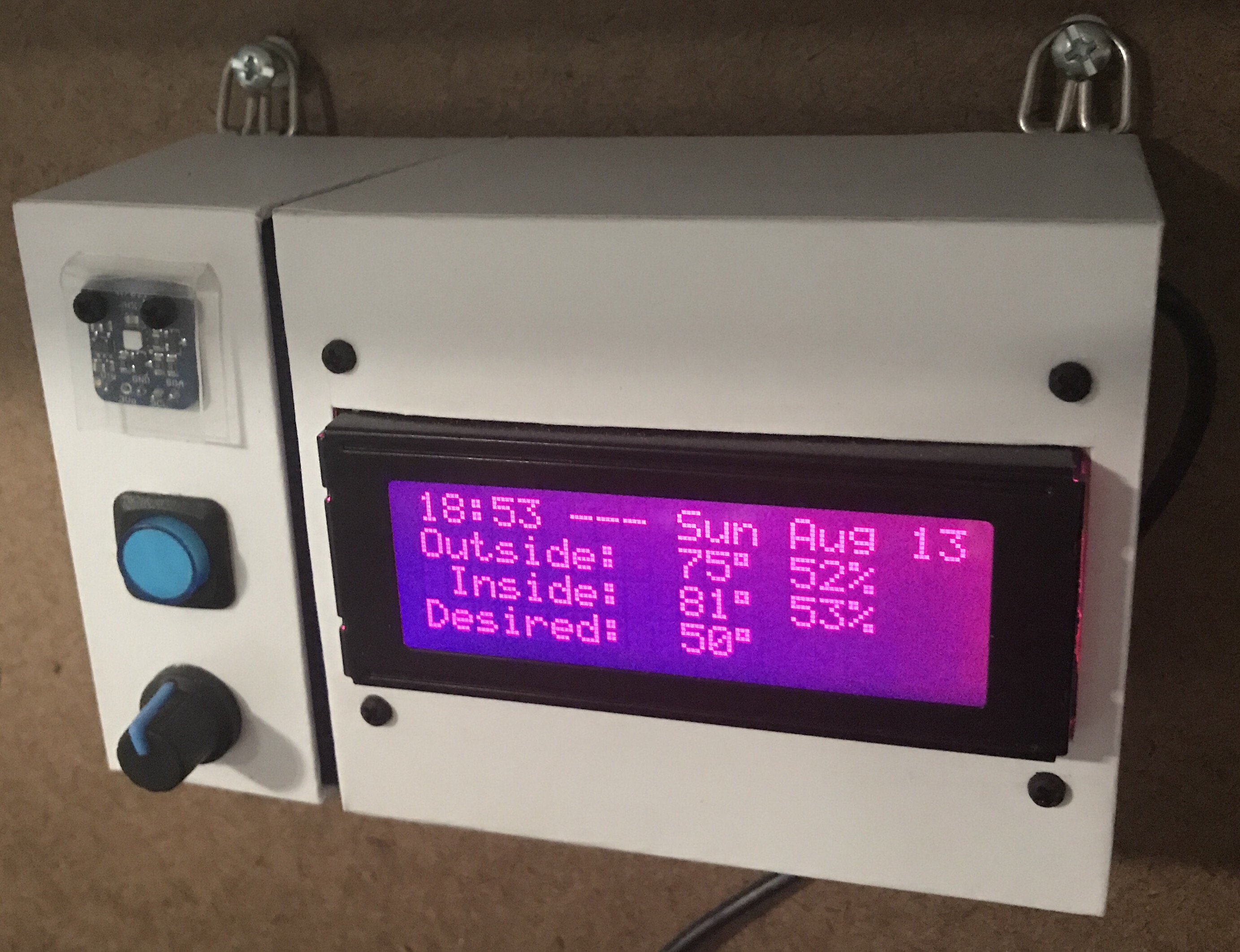
Here’s what my display looks like.
My favorite aspect of the project and code is being able to publish MQTT messages from Home Assistant, which the PyPortal listens for and reacts to. I can send various commands, such as fill:blue, which turns all of the LEDs blue, or whatever color I set. I have commands to chase a color from one side to the other, bounce a color from left to right and back to the left, pulse the entire strip, animate a rainbow, or set the brightness. Since I don’t have another strip of Neopixels, in order to create a demo video, I wired up a 24 LED circle. You’ll have to imagine the effects on the back of my desk, lighting up the wall.
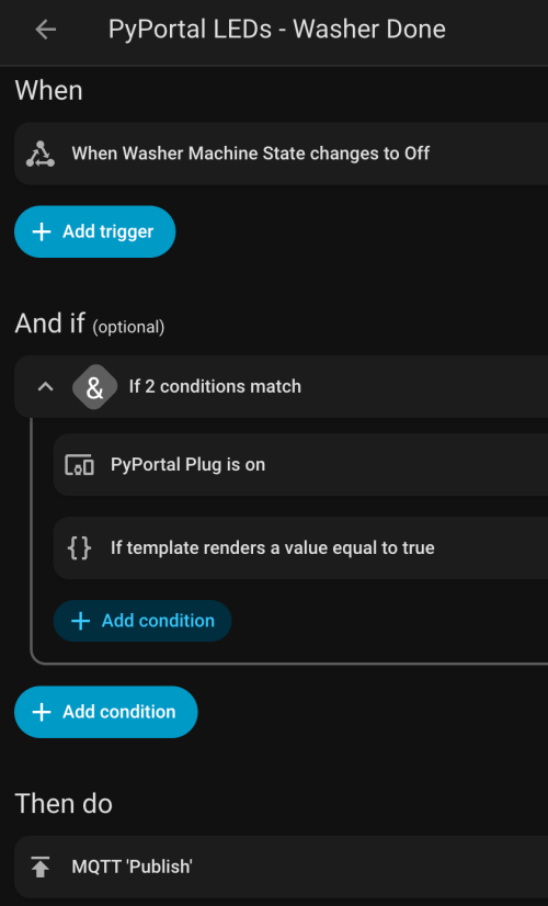
I can manually send these MQTT messages as shown in the demo, but the real power comes from automations. For example, the LEDs automatically pulse blue when the washing machine is done and pink when the dryer is done.
With the different effects and color combinations, the possibilities are endless. What kind of automations would you run?
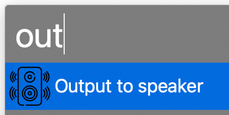
When playing music I usually change my office MacBook’s sound output to a Sonos speaker, which is an AirPlay device. Sometimes the connection freezes and I have to reset output my default device and back to the office speaker. I wanted to automate both of these processes, so I found an AppleScript as a starting point. I modified it and created an Alfred Workflow with a keyword trigger. Here’s my version of the AppleScript. Feel free to modify it for your own use.
	-- This script can be used to set/reset the sound output

	-- Two devices because sometimes the AirPlay device loses connection
	set myDevices to {"LG UltraFine Display Audio", "Office"}

	tell application "System Settings"
		-- sometimes it is already open to Sound, which causes an error
		quit
		delay 0.2
		activate
		delay 0.2

		tell application "System Events"
			tell process "System Settings"
				delay 0.4
				set theWindow to first window
				delay 0.4
			end tell

			keystroke "Sound"
			delay 0.5

			tell application process "System Settings"
				tell its group 2 of scroll area 1 of group 1 of group 3 of splitter group 1 of group 1 of window "Sound"
					tell its radio button 1 of tab group 1
						click
					end tell

					delay 0.3

					tell its scroll area 1
						try
							set theRows to (every row of outline 1)
						on error error_message number error_number
							--display dialog "Error: " & the error_number & ": " & the error_message buttons {"OK"} default button 1
						end try

						repeat with myDevice in myDevices
							set device to myDevice as string

							set found to false

							-- Sometimes the device isn't listed yet, so delay and retry
							repeat 10 times
								repeat with aRow in theRows
									try
										if name of static text 1 of group 1 of UI element 1 of aRow is equal to device then
											set selected of aRow to true
											set found to true

											set volume without output muted
											set volume output volume 10 --100%

											exit repeat
										end if
									on error
										--display dialog "Error setting output sound to " & device
									end try
								end repeat

								if found = true then
									exit repeat
								end if

								delay 0.5
							end repeat
						end repeat
					end tell
				end tell
			end tell
		end tell

		quit
	end tell
Updated on November 28, 2023 to work with macOS Sonoma 14.1.1.
Updated on March 13, 2024 to retry multiple times if device isn’t listed yet.
Updated on March 21, 2024 to reset volume per device, since the OS remembers the last volume of each device.
Updated on October 8, 2025 to work with MacOS Tahoe 26.0.1.
A couple of weeks ago I wanted to display emoji country flags from 2 letter country codes. I couldn’t find PHP examples anywhere. Character encodings confuse me, but after looking at some JavaScript examples and other PHP encoding info I was able to get something working.
I’m behind on a bunch of electronics subscription boxes and projects, so I’m just going to list out a bunch of stuff. None of its worthy of its own post anyway.
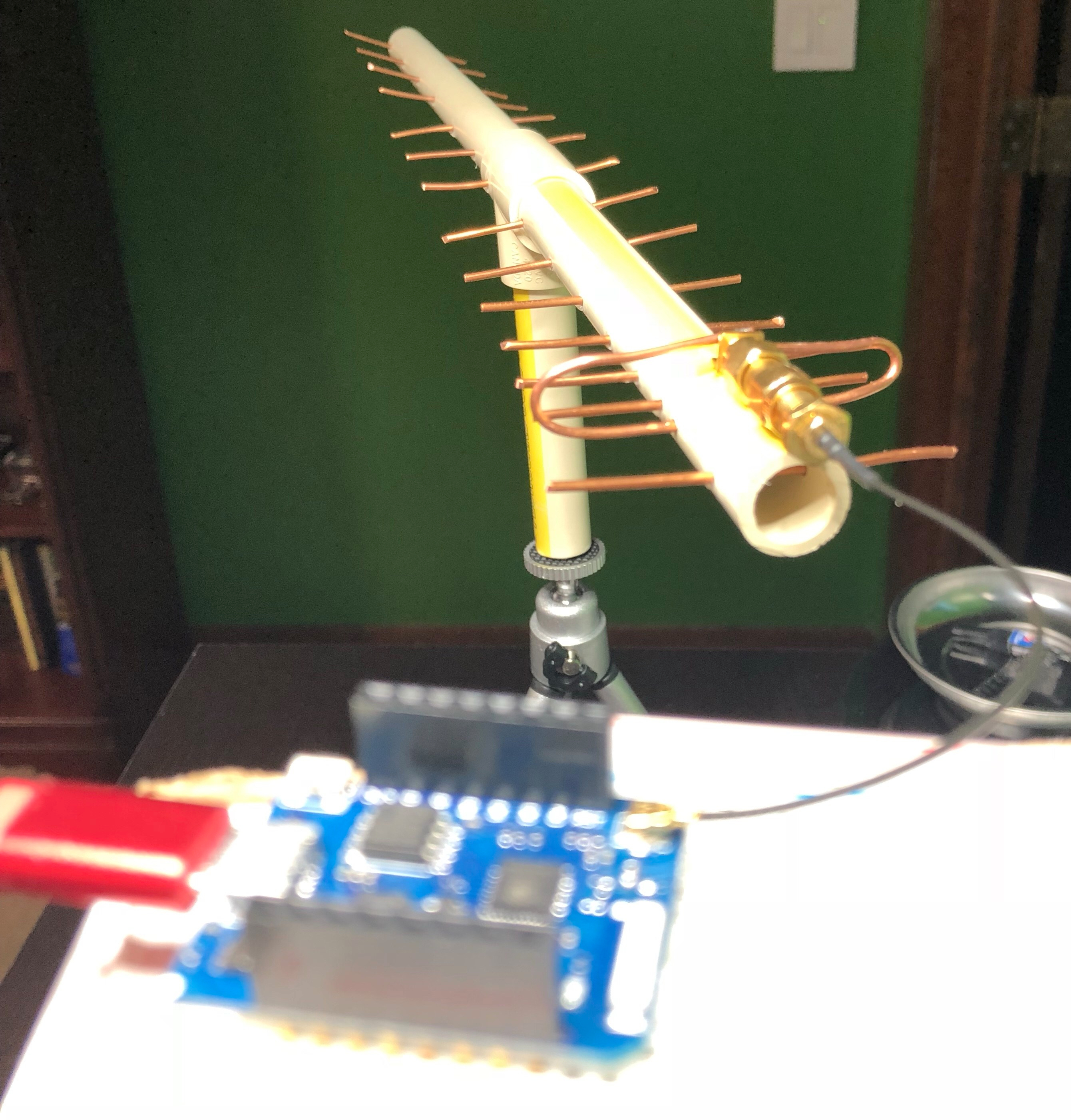
One of the projects for HackerBox #0023 was to build a custom antenna out of PVC, copper wire, and glue. I did a pretty piss poor job of drilling my holes in a straight line (as you can see in the picture), but I connected it to a microcontroller and was able to scan for Wi-Fi networks in the area. Success?
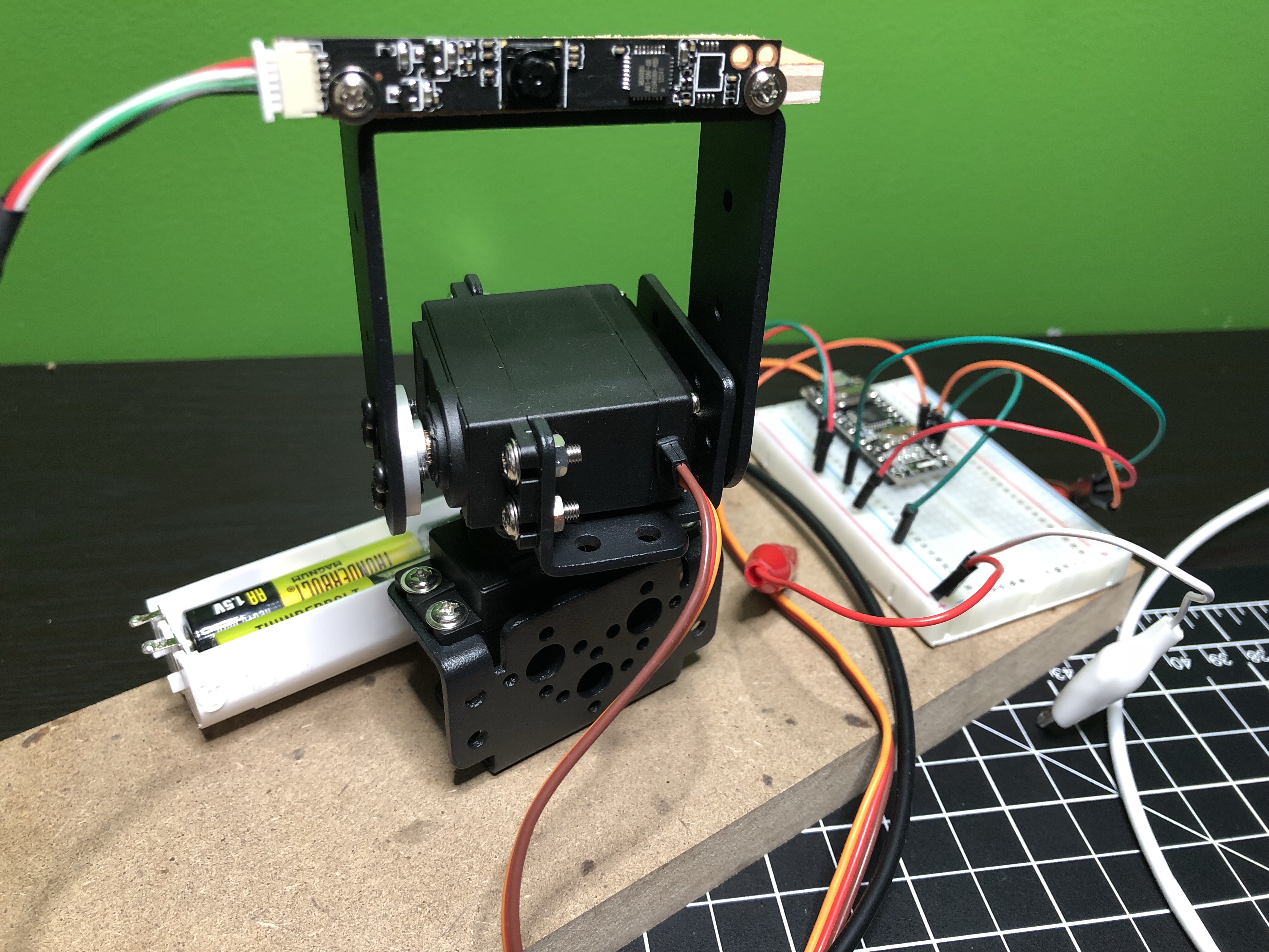
I need to make more time to work with the pan and tilt system built with HackerBox #0024.
The camera that came with the project can only do 640×480, which sucks. One of these days I’ll connect the system to a Raspberry Pi and use one of my unused Pi cameras instead. Would be neat to mount at the front door to track anyone who comes to the house when I’m not home. The face tracking stuff is pretty awesome, even with the shitty camera. Here’s a really rough video of it.
I had to modify the code a lot to get everything working and I put it all on GitHub. If I work on this project more I’ll update that repo.
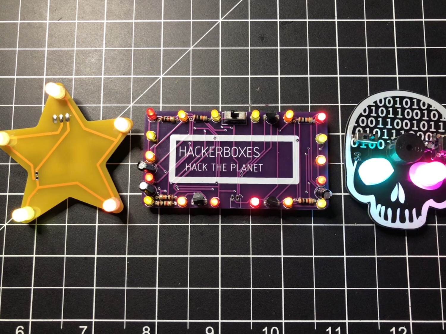
There wasn’t a lot to do with HackerBox #0025. It was mostly a soldering and look at the blinky lights project. Here are the 3 badges I made. I turned the star and rectangle (with a “Let’s Party” sticker in place) into pins and gave them to my nieces.
The skull badge has a buzzer on it, so I wrote some code (it’s on GitHub) to make it play the Star Wars theme and display some light animations.
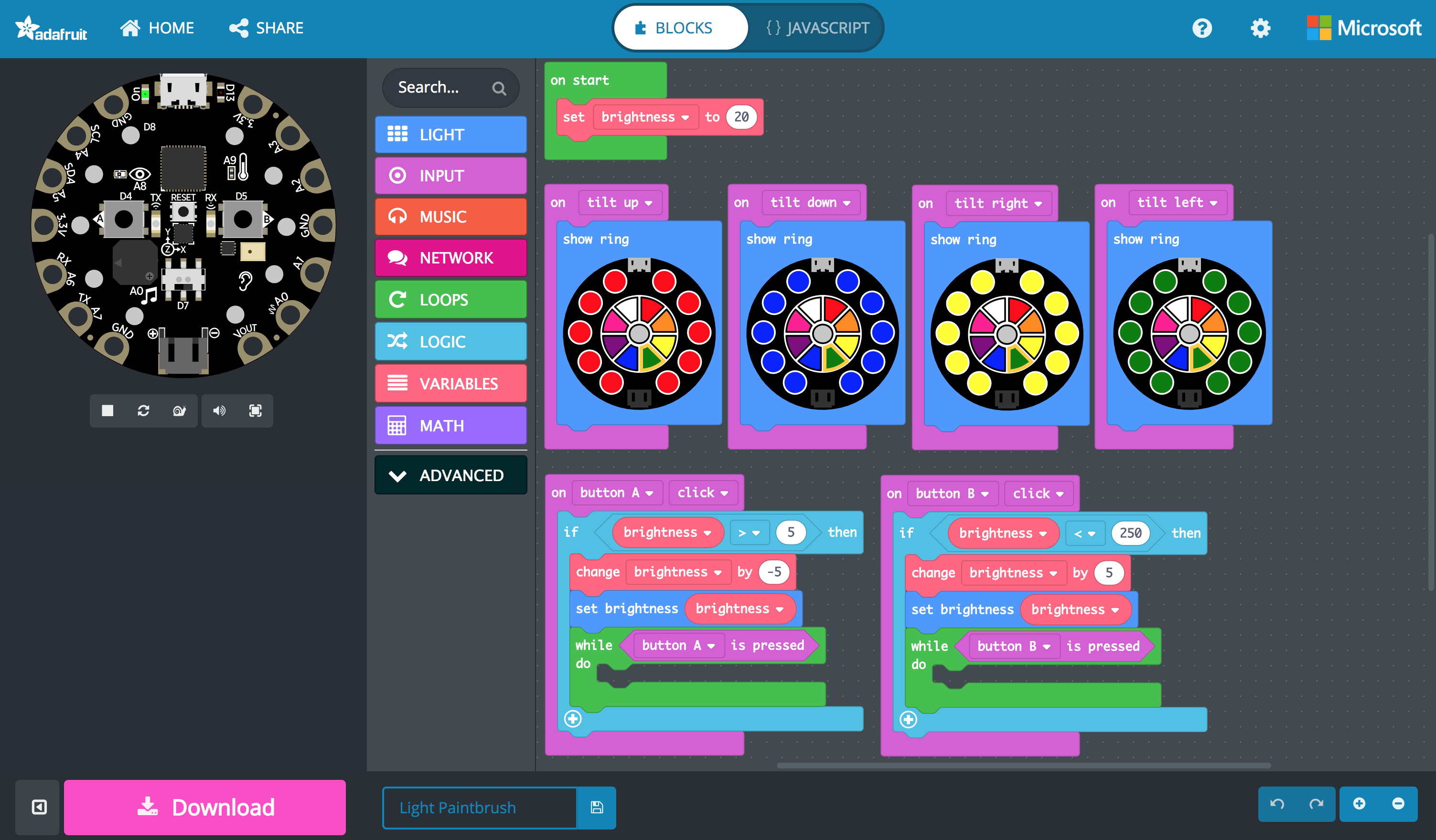
Over the holidays I messed with AdaBox006 a bit. The 38 I posted on my birthday was a light painting taken with the Slow Shutter iOS app. I got it the light paintbrush working on both the Circuit Playground classic via a customized Arduino sketch and on the Circuit Playground Express through MakeCode. Both are available in the adabox-006 repo on GitHub. Using MakeCode is a fun way to program and I think it’s going to change the way people learn. Look at how simple and visual that version of the program is…
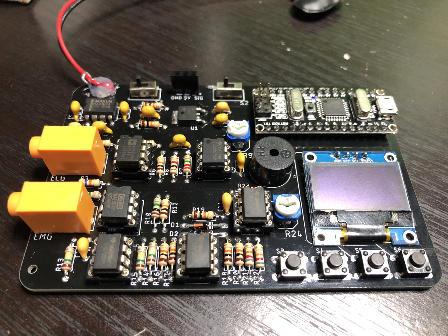
I did solder everything for HackerBox #0026 and verified some of the functionality, but haven’t done much with it. It was one of the most fun projects so far from HackerBoxes because of how many components were on this PCB. I find soldering to be so relaxing and satisfying.
Since I work on our HR team at Automattic, sometimes I need to write code dealing with payroll. When someone starts or leaves we have to pay them for a partial period, which is based on the number of week days. Originally I wrote a simple function, but I set out to make it more useable. Here is what I came up with…
/**
 * Counts the days (optionally limited by type of day) between (inclusive) two dates.
 *
 * @param string $start_date First day (Y-m-d format).
 * @param string $end_date   Last day (Y-m-d format).
 * @param array  $types      Optional. Types of days to count. Default to all types
 *
 * @return int Number of days matching the $types.
 */
function get_days_between_dates( $start_date, $end_date, $types = array() ) {
	$count = 0;

	$included_day_type_indexes = array();
	if ( empty( $types ) ) {
		$included_day_type_indexes = range( 1, 7 );
	} else {
		foreach ( $types as $type ) {
			switch ( strtolower( $type ) ) {
				case 'weekday':
					$included_day_type_indexes = array_merge( $included_day_type_indexes, range( 1, 5 ) );
					break;
				case 'weekend':
					$included_day_type_indexes = array_merge( $included_day_type_indexes, range( 6, 7 ) );
					break;
				case 'monday':
				case 'mon':
					$included_day_type_indexes[] = 1;
					break;
				case 'tuesday':
				case 'tues':
				case 'tue':
				case 'tu':
					$included_day_type_indexes[] = 2;
					break;
				case 'wednesday':
				case 'wed':
					$included_day_type_indexes[] = 3;
					break;
				case 'thursday':
				case 'thurs':
				case 'thur':
				case 'thu':
				case 'th':
					$included_day_type_indexes[] = 4;
					break;
				case 'friday':
				case 'fri':
					$included_day_type_indexes[] = 5;
					break;
				case 'saturday':
				case 'caturday':
				case 'sat':
					$included_day_type_indexes[] = 6;
					break;
				case 'sunday':
				case 'sun':
					$included_day_type_indexes[] = 7;
					break;
			}
		}

		$included_day_type_indexes = array_unique( $included_day_type_indexes );
	}

	$date = strtotime( $start_date );
	$end = strtotime( $end_date );
	while ( $date <= $end ) {
		if ( in_array( date( 'N', $date ), $included_day_type_indexes ) ) {
			$count++;
		}

		$date = strtotime( '+1 day', $date );
	}

	return $count;
}

/*** EXAMPLES ***/

echo get_days_between_dates( '2017-08-21', '2017-09-03' ) . "\n";
echo get_days_between_dates( '2017-08-21', '2017-09-03', array( 'weekday', 'weekend' ) ) . "\n";
echo get_days_between_dates( '2017-08-21', '2017-09-03', array( 'mon' ) ) . "\n";
echo get_days_between_dates( '2017-08-21', '2017-09-03', array( 'weekday' ) ) . "\n";
echo get_days_between_dates( '2017-08-21', '2017-09-03', array( 'mon', 'wednesday', 'fri' ) ) . "\n";
My garage temp sensor, running home-assistant-temperature-monitor stopped working several months ago. I didn’t have time to figure it out and then summer hit, when it’s not important since I don’t heat up the garage before I workout. This weekend I finally got around to troubleshooting the problem.
Turned out I needed to install Adafruit_Python_GPIO. I must have updated my code at some point without fully testing, otherwise I’m not sure how any of it worked before. I didn’t investigate that though; I was more concerned with fixing it and doing some improvements. I updated the OS and everything on the Raspberry Pi since it hadn’t been turned on in quite some time.
Earlier this year, another Pi on my network, the one running Home Assistant and Pi-hole, ran out of disk space without warning. I’ve wanted to put in a notification system so it never happens again, so I updated home-assistant-pi to report the disk use % to HA. I added an automation to notify me whenever it’s above 90% for one of my Pis. I also reworked all of the automations in home-assistant-pi to make it easier to configure each time I get a new Pi.
That all took much longer than I expected. Most of the trouble was trying to understand the Jinja template system used in HA and where it can be applied to configurations. I think I’m finally getting the hang of it.
While writing this post, I found an old draft with some other updates to home-assistant-pi I never published. Maybe I never finished and that’s why everything stopped working! Here’s a list of some previous updates:
Fixed errors causing program to crash.
It wasn’t reconnecting very well, especially if Home Assistant went away (ex. for a restart after an upgrade). Rewrote how the MQTT connection works.
Switch from PushBullet to iOS notifications.
Changed show/hide Home Assistant group automations.
Now that this stuff is running again and I have a better understanding of the Home Assistant automation capabilities, I need to continue the series of posts I planned on home automation. It’s been five and a half months since I published Part 1!
MicroUSB port for programming and debugging with Arduino IDE
USB port can act like serial port, keyboard, mouse, joystick or MIDI
10 x mini NeoPixels, each one can display any color
1 x Motion sensor (LIS3DH triple-axis accelerometer with tap detection, free-fall detection)
1 x Temperature sensor (thermistor)
1 x Light sensor (phototransistor)
1 x Sound sensor (MEMS microphone)
1 x Mini speaker (magnetic buzzer)
2 x Push buttons, left and right
1 x Slide switch
8 x alligator-clip friendly input/output pins
Includes I2C, UART, and 4 pins that can do analog inputs/PWM output
All 8 pads can act as capacitive touch inputs
Green “ON” LED so you know its powered
Red “#13” LED for basic blinking
Reset button
With so many features, Circuit Playground is a perfect board for someone learning to program. There are endless possibilities for fun projects. I ordered one to support the program. I’m hoping they’ll get some of the new Circuit Playground Express boards in stock and extend this promotion to those because I’ve been tempted to get my hands on one. If they do, I’ll gladly place another order.
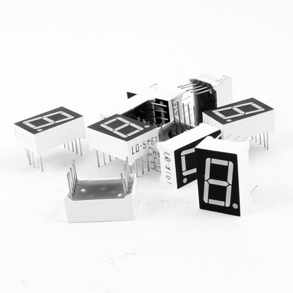
I picked up a 10 pack of these 7 segment red LED displays for less than $5. Since each display requires connecting to a minimum of 8 of the 10 pins (9 if using the decimal point), they aren’t exactly easy to work with. Sure, you can buy these where 2 or 4 displays are already connected in a nice package, controlled with the help of an integrated circuit, but where is the fun in that?
If you need to use more than 1 or 2 displays (at 8-9 pins per display), you’ll quickly run out of pins on your microcontroller or Raspberry Pi. The most common way to work with several of these displays is called multiplexing. It’s a method where you briefly turn on one display, turn it off, turn on the next one, and turn it off. You repeat this through all of your displays and then start over. If you do this fast enough, the human eye thinks all of the displays are on at once. It’s pretty slick!
The advantages of multiplexing are:
Fewer wires/pins needed to drive the displays.
Lower power consumption since the LEDs on only one display are lit.
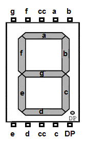
Seven of the pins on one of these displays match up to the 7 segments (labeled a through g), one pin is for the decimal point (DP), and the two remaining pins can be used for the common cathode (cc), though you only need to connect one or the other. Over to the right you can see how all of the pins and LED segments are arranged. Pretty straight forward.
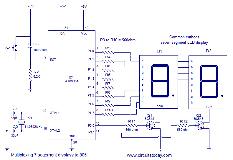
I’m using 6 of these displays in a project, so I needed a lot of wires. It got complex and tangled in a hurry, but amazingly, I connected all the wires without a single mistake on my first try. 🙂 For the most part, I based my circuit design off of this schematic…
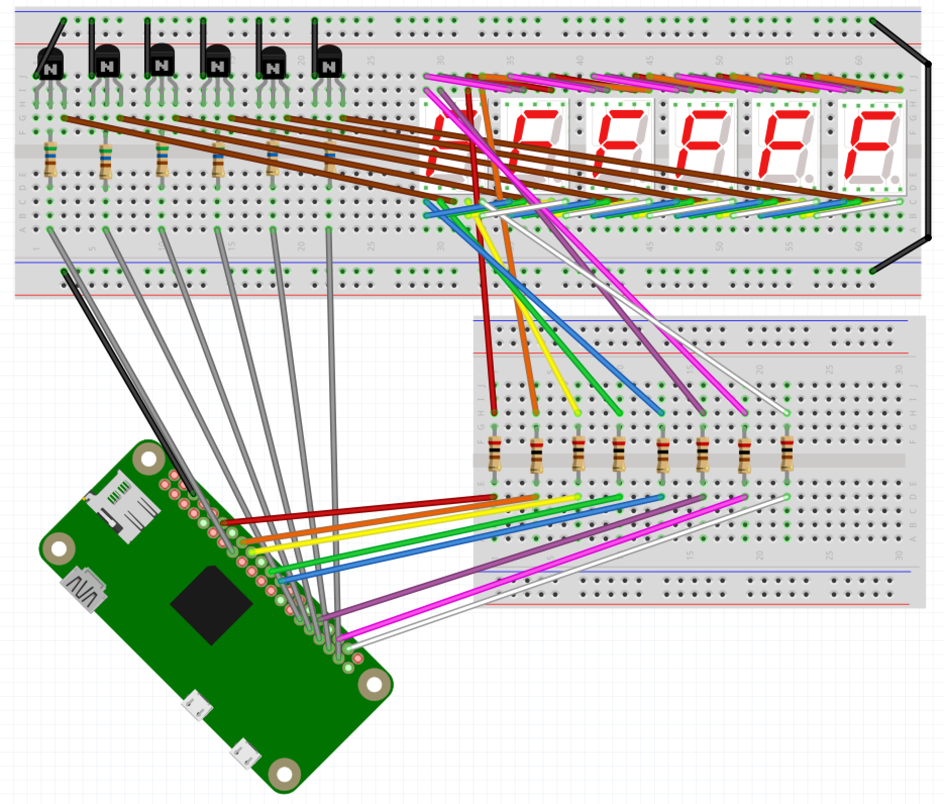
Image source: circuitstoday.comThe end result is something like the Fritzing screenshot below. With so many wires overlapping, it’s not easy to see what’s really going on here. I suggest grabbing wiring.fzz from my GitHub repo and playing around with it in the Fritzing app.
When I went to write my proof of concept code, I decided to use the Gpiozero Python library to simplify working with the LEDs. The library allowed me to set up a couple of arrays for the LED segments and the 6 digits (displays)…
segment_leds = []
for i in range( len( segment_pins ) ) :
segment_leds.append( LED( segment_pins[i] ) )

digits = []
for i in range( len( digit_pins ) ) :
digits.append( LED( digit_pins[i] ) )
Then I could easily loop through and toggle the LEDs in a display as necessary…
for i in range( len( digits ) ) :
for j in range( 7 ) :
if ( numbers[ digit_values[i] ][j] ) :
segment_leds[j].on()
else :
segment_leds[j].off()
To make sure things worked I count up from 999000 and then start back at 000000 after hitting 999999. You can see the full code on GitHub.
Now for some visual proof that I actually got it all working! Here it is running when I keep one digit lit for 5/10,000th of a second before turning it off and lighting the next digit.
You’d never know that only one digit is turned on at a time, would you?
If I change from 0.0005 to 0.05 of a second you can start to see that only one display is on at any point in time.
You may also notice it’s counting up a low slower due to the way this code increments the counter. Don’t worry about that.
When I keep each digit turned on for half of a second you can really see how this works.
An issue I’m running into on a Pi Zero is when the processor gets busy doing other tasks, there is a bit of flicker across the displays. You can see this a couple of seconds in to the first video. I’m guessing the code would perform much better on a Raspberry Pi 3B. For my project it’s not a concern, but I want to mention it in case you follow this for your own project. You may also pick up what looks like random flickering of a single digit here and there but that’s due to video timing; the human eye doesn’t see any of that when it’s in front of you.
If necessary, you can take multiplexing a step further and only light up an individual LED on each display at a time, with a method called charlieplexing. It will use even less power, but due to the speed at which you need to switch from one LED to the next, especially across an array of multiple displays, you lose brightness to the human eye.
Every time I update an SVN external to a new tagged release I have to look up this damn command. I have it saved in a Bear note containing SVN tricks. Finally added an alias to .bashrc on my work sandbox.
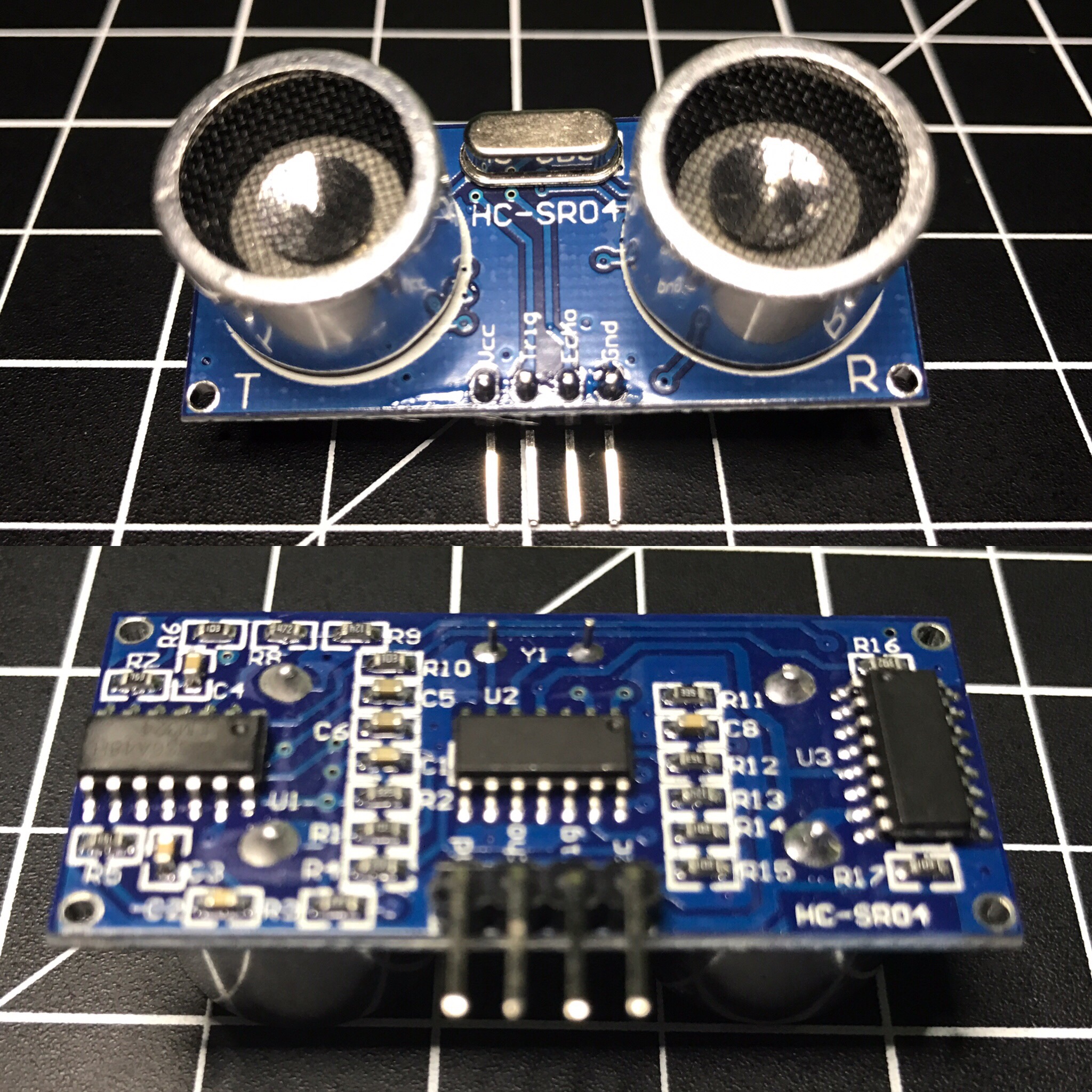
The HC-SR04 ultrasonic sensor uses sonar to determine distance to an object like bats do. It offers excellent non-contact range detection with high accuracy and stable readings in an easy-to-use package. From 2cm to 400 cm or 1” to 13 feet. Its operation is not affected by sunlight or black material like Sharp rangefinders are (although acoustically soft materials like cloth can be difficult to detect). It comes complete with ultrasonic transmitter and receiver module. Complete Guide for Ultrasonic Sensor HC-SR04
You can get the HC-SR04 from Amazon or various electronics shops for $3-5 or even under $2 if you buy packs of them. I got 2 of them in a parts kit I bought on Amazon and used one for Blog in a Box Paparazzi.
I was using the sensor to sort of detect motion, or more specifically when someone walked into a room. My prototype was set on a desk at about chest height about 1-2 feet after the doorway. While working on the project I ran into several challenges:
def read_ultrasonic() :
	# Make sure the trigger pin is clean
	GPIO.output( ULTRASONIC_TRIG_PIN, GPIO.LOW )
	# Recommended resample time is 50ms
	time.sleep( 0.05 )
	# The trigger pin needs to be HIGH for at least 10ms
	GPIO.output( ULTRASONIC_TRIG_PIN, GPIO.HIGH )
	time.sleep( 0.02 )
	GPIO.output( ULTRASONIC_TRIG_PIN, GPIO.LOW )

	# Read the sensor
	while ( True ) :
		start = time.clock()
		if ( GPIO.input( ULTRASONIC_ECHO_PIN ) == GPIO.HIGH ) :
			break
	while ( True ) :
		diff = time.clock() - start
		if ( GPIO.input( ULTRASONIC_ECHO_PIN ) == GPIO.LOW ) :
			break
		if ( diff > 0.02 ) :
			return -1

	return int( round( diff * 17150 ) )

def is_ultrasonic_triggered() :
	global prev_ultrasonic

	# Take 6 readings
	for i in range( 6 ):
		ultrasonic = read_ultrasonic()
		#Shift readings
		prev_ultrasonic = ( prev_ultrasonic[1], prev_ultrasonic[2], prev_ultrasonic[3], prev_ultrasonic[4], prev_ultrasonic[5], ultrasonic )

		if ( is_light_enough()
				and prev_ultrasonic[0] != -1
				and prev_ultrasonic[3] < ULTRASONIC_DIST and prev_ultrasonic[4] < ULTRASONIC_DIST and prev_ultrasonic[5]  ULTRASONIC_DIST and prev_ultrasonic[1] > ULTRASONIC_DIST and prev_ultrasonic[2] > ULTRASONIC_DIST ) :
			#print 'Ultrasonic: {0}'.format( prev_ultrasonic )
			return True

	return False

while ( True ) :
	if ( is_ultrasonic_triggered() ) :
		take_picture()
It worked alright, but triggered a little too often. About a week later I came across the Python package gpiozero, which makes it easy to work with a bunch of common Raspberry Pi GPIO components. I wrote an alternate version of BIAB Paparazzi using this package, which worked a bit better. It was so much simpler with gpiozero because it has built-in support for the HC-SR04. All I had to do was initialize the sensor and tell it what code to run when something in range was detected.
The neat thing about the gpiozero package is when you initialize a sensor it automatically starts taking readings, keeps the values in a queue, and does comparisons against an average. My code attempted to do something along those lines, but was much more rudimentary. As nice as this version sounds, it still triggered too often. You can find the complete code for both versions in the BIAB Paparazzi repo on GitHub.
I think I was pushing the limits of what the HC-SR04 is meant for. Most of the examples I’ve seen are people using these to detect approaching walls on a robot. The biggest issue I ran into was the inaccurate readings. For example I’d be getting readings of about 160cm and then out of nowhere it would return a distance of 80-90 cm, even several in a row at times.
At the end of the day there are reasons it’s such a cheap sensor. 😉 For a couple of dollars, what do you expect? I’m curious to try my code on a more powerful Raspberry Pi 3 and see if it works any better. Was the less powerful Pi Zero causing problems?