In parts 1 and 2, I walked through my journey of repurposing the keypad out of a phone from 1980. I learned that a more modern keypad matrix doesn’t exactly function (behind the scenes) in a way I’d expect. I wanted to understand it better so I set out to recreate a 2×2 keypad (kept it simple to make wiring easier) that would function the same way as something you can buy today. It would be a success if it worked with the Arduino Keypad Library.
From my earlier looks through the code I knew it pulsed power out to a column pin and then read in each row’s key from that column before switching to the next column and repeating the process. I figured that should be enough for me to wire this up and try example programs without going back to look at the library’s code again.
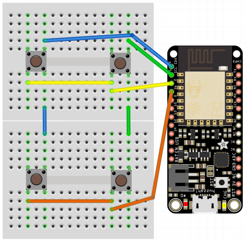
I don’t know why I was thinking this would be more complicated and at least a little more exciting, but it was unbelievably easy. I guess I should be celebrating I understood how it worked. Literally all you do is connect one side of every button in a column to a pin and one side of every button in a row to a pin. No need for connections to power, or ground. No pull up/down resistors.
It immediately worked with the Arduino Keypad library examples, even the MultiKey one. I guess being able to detect multiple key presses at once is where the advantage to this implementation comes in. It worked flawlessly when pressing 2 of the 4 buttons, but when you get to 3/4 there are too many connections to distinguish the keys.
Just to be sure I had it figured out, I added a 3rd column to make it a 2×3 grid and it was just as easy.
I love the beauty of how simple this is. I’ve added Fritzing for both of these to my phone-keypad GitHub repo (2×2 & 2×3). If you check this PDF, in the How it Works section it has a really good explanation and shows the row and column connections exactly like I came up with.
Naturally now I need to do a part 4 and attempt to recreate the keypad implementation I ended up with from the old phone. Due to how it mechanically makes the electrical connections I think it’s going to be a bit more complicated than this was. We shall see…
Remember last week’s post about tearing apart a component switch to repurpose parts? I spent some time fooling around with IR after that. I thought it would be neat to recreate the basic functionality of switching between 3 devices. For my proof of concept the devices were simple the 3 status LEDs, but you can imagine the possibilities of turning on different devices or triggering processes run on a computer.
The new microcontroller I got is one I posted about a few months ago, called Puck.js. It has an IR transmitter built-in, so I wanted to use it to mimic a remote. Puck.js is pretty slick. It’s really neat being able to program a device in Javascript through a web IDE over Bluetooth Low Energy. No wires at all!
Propping a component into the GPIO pins like the author did doesn’t work for shit. You can’t get a solid electrical connection, especially if you bump it at all.
I kept getting Out of Memory errors on the device because the array would get really large really soon.
My next thought was to wire up to one of my other microcontroller that run Arduino, but the popular IR Library (IRLib2) doesn’t support the chips used in any of the boards I have. So over to a Raspberry Pi Zero. Pretty much every search result mentioned using Linux Infrared Remote Control (LIRC). May of the setup instructions I found were incomplete, but I was able to get things running by taking pieces from these two sites:
I’ll detail the steps that worked for me. Before I go down the software route though, I wanted to make sure the IR sensor worked. The only markings on the component are “71M4” and I have been unable to find a datasheet anywhere to match. Luckily these IR receivers are pretty standard and I had a pretty good idea of the pins from looking at how it was connected in the old device. I got the idea of hooking up a simple LED test circuit on the data pin from an Adafruit learn guide. Pin 1 is data, going into a GPIO pin on the Raspberry Pi (26 in my case), pin 2 is ground, and pin 3 is power (VCC). You may want to use the 3.3V pin on the Pi to provide your power instead of 5V just to be safe, or consult the datasheet for the IR sensor you’re using. Connect the anode of the LED to power and the cathode to pin 1 of the sensor using a 220 Ω (I used 200) resistor. When you press buttons on an IR remote, the sensor will send data through pin 1 and the LED will light up. Here’s a Fritzing wiring diagram for this test as well.
My test was successful! Now I was able to move on with some confidence knowing the part worked.
Install LIRC:
sudo apt-get update
sudo apt-get install lirc
Edit the /etc/modules file:
sudo nano /etc/modules
Add to the end:
lirc_dev
lirc_rpi gpio_in_pin=26
Change the pin if you’re using something other than 26. If you’re also going to do IR transmitting, you can add a space and gpio_in_pin=22 on that last line.
Press Ctrl + X, hit Y to say you want to save, and then Enter.
Edit the /etc/lirc/hardware.conf file:
sudo nano /etc/lirc/hardware.conf
Look for the DRIVER, DEVICE, and MODULES settings. Set them to match:
Press Ctrl + X, hit Y to say you want to save, and then Enter.
Edit your /boot/config.txt file:
sudo nano /boot/config.txt
Look for this line:
# Uncomment this to enable the lirc-rpi module
If you see it, remove the # from the next line and edit it to look like this (if your file doesn’t have it, add this to the end of the file):
dtoverlay=lirc-rpi,gpio_in_pin=26
If you’re going to do transmitting, also add this to the same line:
,gpio_out_pin=22
Change both pins to match whatever you’re using. Press Ctrl + X, hit Y to say you want to save, and then Enter.
Reboot your Pi:
sudo reboot
Now it’s time to use LIRC to record the codes sent by whatever remote you’re using. First you’ll want to see names you want to give your buttons. Run:
irrecord --list-namespace
Scroll through the list and make notes on all of the codes you want to use for your buttons. You’ll need the codes in a bit. Here was my list:
KEY_POWER
KEY_1
KEY_2
KEY_3
Stop LIRC:
sudo /etc/init.d/lirc stop
Use irrecord to create a configuration file for your remote. Follow the instructions carefully that come up on your screen. This took me several minutes for my remote with only 4 buttons.
Note: When it says Please enter the name for the next button (press to finish recording) is when you’ll need those codes above.
irrecord -d /dev/lirc0 ~/lircd.conf
When finished you’ll have a new file in your home directory. Take a look at it:
cat ~/lircd.conf
Mine looked like:
begin remote

  name  /home/pi/lircd.conf
  bits           16
  flags SPACE_ENC|CONST_LENGTH
  eps            30
  aeps          100

  header       9004  4474
  one           580  1666
  zero          580   542
  ptrail        578
  repeat       9006  2229
  pre_data_bits   16
  pre_data       0x61D6
  gap          107888
  toggle_bit_mask 0x0

      begin codes
          KEY_POWER                0x7887
          KEY_1                    0x40BF
          KEY_2                    0x609F
          KEY_3                    0x10EF
      end codes

end remote
Make a backup of the default LIRC configuration file:
You need to set up each button similar to what mine looks like:
begin
  remote = *
  button = KEY_POWER
  prog = pylirc
  config = KEY_POWER
end

begin
  remote = *
  button = KEY_1
  prog = pylirc
  config = KEY_1
end

begin
  remote = *
  button = KEY_2
  prog = pylirc
  config = KEY_2
end

begin
  remote = *
  button = KEY_3
  prog = pylirc
  config = KEY_3
end
Do a simple copy/paste and change the button and config for each entry.
Press Ctrl + X, hit Y to say you want to save, and then Enter.
Create a basic Python test program:
nano pylirc-test.py
Paste in:
#!/usr/bin/python

import pylirc

pylirc.init( 'pylirc', './pylirc.conf', 0 )

while ( True ) :
	s = pylirc.nextcode( 1 )
	command = None
	if ( s ) :
		for ( code ) in s :
			print( code["config"] )
Press Ctrl + X, hit Y to say you want to save, and then Enter.
Run the program:
python pylirc-test.py
Press buttons on your remote and if everything is working you’ll see the special name codes being output for each button you press.
Hit Ctrl + C to stop the program.
I already had all of the logic written for the buttons to work and switch LEDs, so it was easy to add in a little more code to take action when the appropriate IR codes were received.
Once I found the correct information, setup on the Pi was quite easy. A lot of steps, but easy stuff. Making the Puck.js duplicate my Infrared remote’s codes was a bit of a challenge. From the Puck.js Infrared tutorial I linked at the beginning I knew I needed to have an array of pulse lengths, but I didn’t have anything like that from the LIRC configuration. All I had was some hex values for each code:
KEY_POWER: 0x7887
KEY_1: 0x40BF
KEY_2: 0x609F
KEY_3: 0x10EF
Combined with another hex code for pre_data (0x61D6) from the lircd.conf file, I had more complete codes:
Infrared remote control signals from the LIRC remote configurations project, converted to Pronto Hex and Protocol, Device, Subdevice, and Function using lirc2xml…
BINGO! It had the Pronto Hex codes. I cloned the repo and started searching for my hex values. I found power, 1, and 2 matched up with codes used by something called a gigabyte TV. I plugged the codes into a program and they worked! I was only missed the code for button 3.
Then I spend way too much time still searching around. I knew enough about how IR worked and had 3 codes. I finally realized I should be able to figure out what changes to make in order to get my 4th and final code. I converted the hex values to binary:
KEY_POWER: 0x7887 = 111100010000111
KEY_1: 0x40BF = 100000010111111
KEY_2: 0x609F = 110000010011111
KEY_3: 0x10EF = 001000011101111
Then I started looking at the end of each array of Pronto Hex codes, because every code uses the same pre_data. I quickly determined an ON bit (1) was 003e, OFF (0) was 0013, and they were separated by 0017. I made the necessary adjustments and had all 4 buttons working with IR!
This IR journey turned out to be quite an adventure. I learned a lot, which was the point. My infrared-3-input-selector project on GitHub has the Python program used in the demo video, my pylirc config file, the simple pylinc test program, the Puck.js code, and even an Arduino sketch with the button and LED logic I created initially before realizing I needed to switch to the Raspberry Pi.


 I got
I got 

