J.J. Spaun, who won the U.S. Open yesterday, has the DF3 in his golf bag, so this seems like the perfect time to write about the time I’ve spent with mine. Spaun, who switched to the DF3 at the beginning of the year, was second in the field for strokes gained putting and gained over 10.5 shots with the flat stick!
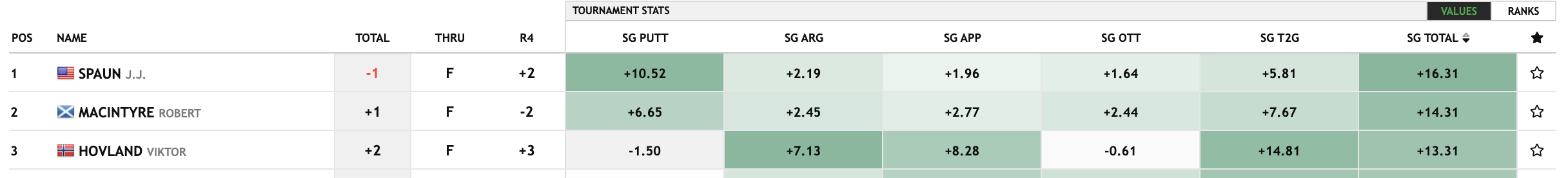
His putting accounts for 64.5% of the 16.31 total strokes he gained on the field, which is impressive. SG came from datagolf.com. I believe this is the first major win by someone using a L.A.B. putter and surely won’t be the last.
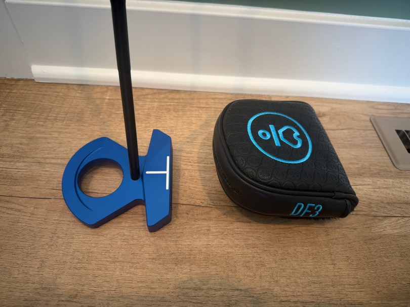
I’ve had my DF3 for two months now and I love it. The first two and a half weeks weren’t great though, because I wasn’t using the putter correctly. After some research and experimentation I made changes to my stance and grip. My feel has been brilliant since.
I’d always played traditional putters in the middle of my stance, as I suspect most people do. This shaft is different because it’s offset behind the club face. You have to line up with the ball quite a bit forward in your stance, otherwise the face is open at impact. Here’s a video from the L.A.B. Golf talking about it for the DF 2.1.
Another change that really helped me was adjusting my grip. I had to lighten the pressure applied with my hands so the face can properly square itself up. I also slid my right hand more underneath the grip to limit its influence on my putting stroke. I used their suggestion of the thumbs off drill to get some feel for it and figure out what was comfortable for me.
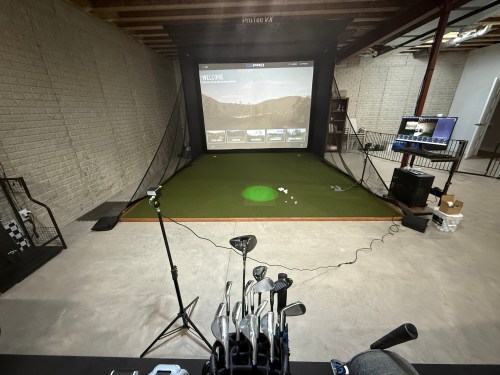
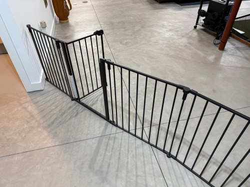
Then it was a lot of practice, focused on start line. I got this idea from a Lou Stagner thread on Twitter/X. When I practice, I hit 10 putts at a distance of about 10-11 feet and I use the Putting Thing from WhyGolf with all gates set to level 2.

I only ever putt 10 at a time and I record each session. Since I got the putter, I’ve done this 94 times, so I’m struck almost 1,000 practice putts like this. In order to get the passing grade the ball and putter can’t touch any of the gates. I don’t even care what the ball does at the cup. It’s all recorded in a spreadsheet and the chart below shows revolving 100 putt blocks. For example, the first bar includes the first 10 times I played a practice session, the second bar is practice sessions two through 11, and so on.

The last low point under 50%, was right before I made the changes. It was a steady rise from there as the bad sessions fell out of the last 100 attempts and then I’ve consistently been around 80% or better.
There is more pressure and less than perfect conditions on the golf course though. How am I doing there? I grabbed some putting data from my Shot Scope account. To keep comparisons similar I filtered to rounds at the Sawmill Golf Club, my home course. Here are my 2024 stats, using my previous putter, the Odyssey Red Ball.
Not too bad. I actually gained strokes compared to the average 10 handicap golfer. Here are my stats since May 6th, 2025, when I figured out how to use the DF3.

I’m not making a bunch on my first attempt, actually down 1%, but I’m three putting less than half as much and I’ve gained an extra 1.12 stokes per round. I also pulled the stats for the same 2024 period of dates.

A massive 2.51 strokes better on the greens in 2025 for the same date period.
My start line is better from the lie angle balance technology and practicing with Putting Thing. My distance control is also a lot better from the Directed Force (DF) technology, which is more forgiving on off-center hits.
| Date Period | 3+ Feet Short | 0-3 Feet Short | Within 3 Feet | 0-3 Feet Long | 3+ Feet Long |
| 2024 | 13% | 27% | 75% | 48% | 12% |
| 2024 (May 6 – Jun 16) | 8% | 22% | 76% | 54% | 16% |
| 2025 | 13% | 22% | 81% | 59% | 6% |
I was unable to limit the data in this table by course, so it’s not as good of a comparison and I believe impacts the shortest putts the most because I struggle getting the ball to the hole on slower greens at other courses. Even so, I’m getting 5-6% more putts within three feet of the hole and fewer are racing past.
Can you see why I love this putter? Of course it won’t be everyone’s weapon of choice, but I suspect many people who give up on theirs don’t understand how to use it properly or put in quality practice time.