Looking forward to “House of Cards” season 5. Might be my all-time favorite show.
Author: Nick Momrik
I'm searching for my first hole-in-one.
I enjoy being active and making things.
I work for Automattic.
Electronics Engineering ToolKit
Electronics Engineering ToolKit is a useful iOS app if you’re messing around with electronics. I think I paid $6.99 to upgrade to Pro, which unlocks all of the formulas, reference material, and tools.

I recently posted Using a 555 Integrated Circuit. There are many ways to use these 555s. To get a sense of the power of this app, it has 10 tools in its 555 Timer IC group! Here’s a look at the Monostable operation mode. Each tool in the app has a great info panel like this one, describing what it does.

The tool itself gives 2 inputs where you set your resistor and capacitor values and it calculates the time for you.

It provides a circuit schematic where the R (resistor) & C (capacitor) values are updated instantly, based on you input values. This schematic doubles as a simulation, where it really gets cool. You can tap on the button to see how the circuit reacts. In this case, the LED turns green (ON) for 2.42 seconds and then turns off.

I wired up the circuit to try it for myself. Worked exactly as expected. I even triggered my live circuit and the simulation at the same time and the LEDs turned off simultaneously.

This is just one example of many useful things you can do in the Electronics Engineering ToolKit app, especially with the Pro upgrade. Not only can you favorite (as shown at the beginning of this post) the tools you find most useful, but the app also has a great search feature.
You can find similar tools for specific formulas and uses around the Internet, but I haven’t come across anything where it’s all in one place with an easy to use interface like this. Perhaps the best web site I’ve found is Basic Electronics Tutorials and Revision, which is a bit higher level in the way their descriptions.
“The Erg Book”
375+ of the Greatest Indoor Rowming Workouts of All Time

Won this in a Twitter contest from Concept2.
I flipped through and it covers everything you need to know about indoor rowing including setting up the rower for your body type, technique tips, 14 week training plans, and of course workouts, which are organized by skill level, training goals, time, and difficulty.
Phone Keypad Hacking: Part 1
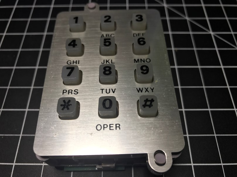
 I’ve been on a kick tearing apart electronics. In addition to the switch I got a bunch of parts from, I’ve tore into a lamp and some old computer speakers. When I found an old telephone (it has a date of 5/30/1980 printed on it!) in my basement I knew I had to see what was inside. The previous owners left it in a storage room and I have no idea why I never pitched it. I didn’t take a picture before taking a screwdriver to it, but it looked exactly like the photo on the right.
People have been hacking phones for a long time. Perhaps the earliest and most well-known was the Steves (Jobs and Wozniak) using a blue box on payphones. I’m nowhere near that level, but you have to start somewhere right? I pulled the ringer, speaker, and microphone out of it. I haven’t messed with these yet.

The part I thought would be neat to work with was this keypad.
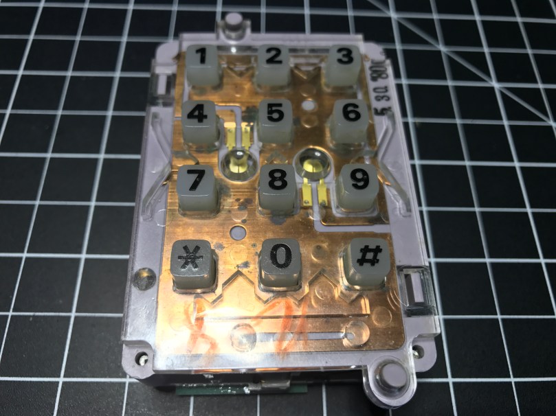

It was a bit of a process figuring out how to tap into this thing. Eventually I realized what these contact switches on the sides were for.

 There are seven of them. The top has two and the bottom has one, which correspond to the 3 columns of keys on the grid. Then the left and right sides each have 2, which match up with the 4 rows of keys.
This row/column grid system is still how we reference the individual keys on keypads like this. Arduino has a Keypad library for working with modern keypads like one sold by Adafruit.
I figured out I could solder wires to the contacts points connected to each of those switches. I was in! From the way the keypad was connected to the rest of the phones circuitry I knew the screws were an important piece to tie it all back into the entire system. After some trial and error I determined which screws should be used for power (red wire) and ground (black) in order to get useable data out of the 7 switch contact points. The other 3 screws also connect to power. I was using alligator clips on those, but disconnected them for the picture.

Something isn’t quite right about the screw connections though. When I connect them the opposite way, flopping to have 1 power and 4 grounds, the backlight on the keypad works, but the readings from the soldered contact points are useless. With them connected this way, I don’t get the backlight, but I get data I can make sense of. There is probably something obvious I’m missing about how this all works together.
Unfortunately for me, the output from the contact points isn’t digital (limited to on/off), so I couldn’t use the Arduino library. It would have made things so much easier. It’s not surprising though, since this piece of technology is almost 40 years old!
I was able to get some code mostly working. Detecting the column of a button press was pretty straight forward and works great. Rows detection is another story. I’m reading in analog values and using sampling along with standard deviations to determine which row’s value is unlike the others. Well, the first row always reads a pretty high value, when a key on any row is pressed. The values for the other rows fluctuate as expected. When that first row is high, I’ve attempted to also look for a high value from another row, but it triggers the wrong row too often.
Demo time…
Even making this short little video, which took at least 5 takes, there was a false trigger for pressing 1 and many key presses not being recognized. Not useable.
I have a hunch the screw connections are responsible, at least in some part, for sending DTMF signals, also known as Touch-Tone. I don’t really care to get in the business of decoding these. This is precisely why I was hoping I could detect useful output from each of the row and column contact points.
I pulled apart the unit even more and discovered a Western Electric 557D is the brains of the operation, but it’s so old there doesn’t seem to be a datasheet online for it. What I’m going to do is remove the PCB and wire up everything on my own. Then I can easily get on/off as digital values from the columns and rows and make sure the backlight works. Stay tuned…
Update: Read Part 2
Link Dump – 2017/04/28
Instagram and Insecurity Netflix will be releasing a true crime series about this young nun’s unsolved murder We Need More Repair Cafés Tesla driver says Model S ‘saved his life’ after walking away unscathed from a crash ~500-ft down a hill Love & breadsticks: There was a knife fight at Olive Garden Giving Credit Where […]
Slack “party”
When I went to add a “party” reaction in a Slack conversation, I noticed we have quite the selection.
Canoe Paddler

Strawberry & Crème Pies

McDonald’s has the strawberry & crème pie back on the menu. These things are amazing! I stopped for a couple after picking up pizza slices for lunch. After putting in my order, the guy working the drive-thru asked, “Would you like to add a free cookie today?” They say there is no such thing as a stupid question.
SVN propedit
Every time I update an SVN external to a new tagged release I have to look up this damn command. I have it saved in a Bear note containing SVN tricks. Finally added an alias to .bashrc on my work sandbox.
alias props='svn propedit svn:externals .'
Test LEDs with a Coin Cell Battery
The battery (CR2450) in my garage door sensor was getting low, so I replaced it. I’ll keep the old one in my electronics kit for LED testing, as shown in this video. Touch the longer leg (anode) of the LED to + and the shorter leg (cathode) to –. Usually + is the top of the battery where the words are. Don’t worry, you won’t hurt the LED if you connect it the wrong way.
