I’ll likely turn this into something that interfaces with my Home Assistant server to control different devices around my house.
The PyPortal has been sitting on a shelf ever since. Way back in February, it caught my eye, and I picked it up, not remembering what it’s capabilities were. Then I started upgrading IKEA air quality monitors and even made my own. Since I’m at the desk in my office a large portion of the week I thought I would make that 2019 prediction come true.
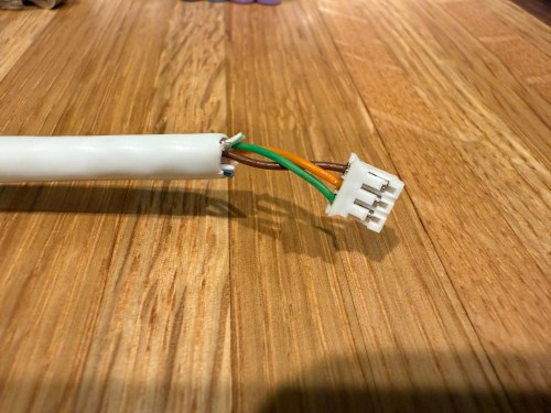
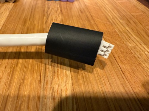
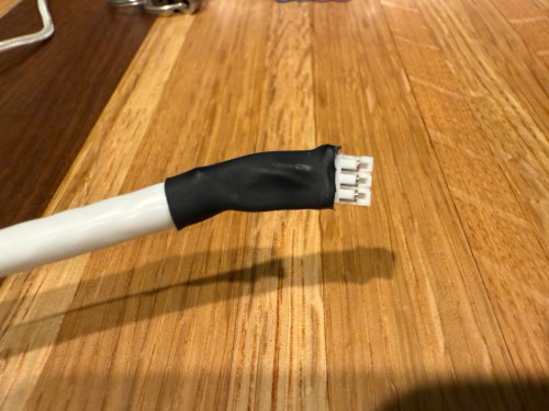
I could show a bunch of data on the screen and the PyPortal has a touchscreen, so I could display buttons for triggering things around the house. The device also has connectors for doing GPIO, so I got the idea of adding an LED strip, which I could use for notifications. I even had a meter long strip of Adafruit Mini Skinny NeoPixels I had bought in 2017 and never touched that would be perfect. I needed to buy a 2.0mm JST PH Connector kit in order to make a wire that would connect to the pack of the PyPortal. I ended up using a piece of Cat6 cable, even though I only needed 3 of the 8 wires inside.
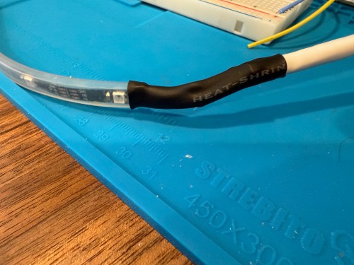
All of this was done back in March. I quickly began having issues with the ethernet cable and the small JST connectors, so I put this post on pause. Figured it was time to finally fix this before the end of the year. While testing, I determined the LED strip got fried up at some point. It was probably some kind of short from the janky wire.
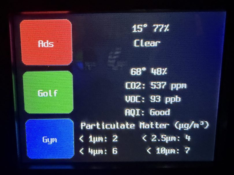
Here’s what my display looks like.
My favorite aspect of the project and code is being able to publish MQTT messages from Home Assistant, which the PyPortal listens for and reacts to. I can send various commands, such as fill:blue, which turns all of the LEDs blue, or whatever color I set. I have commands to chase a color from one side to the other, bounce a color from left to right and back to the left, pulse the entire strip, animate a rainbow, or set the brightness. Since I don’t have another strip of Neopixels, in order to create a demo video, I wired up a 24 LED circle. You’ll have to imagine the effects on the back of my desk, lighting up the wall.
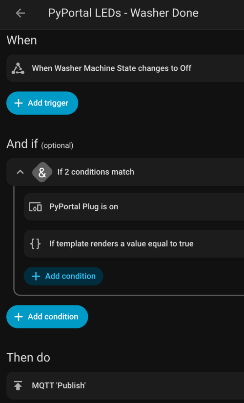
I can manually send these MQTT messages as shown in the demo, but the real power comes from automations. For example, the LEDs automatically pulse blue when the washing machine is done and pink when the dryer is done.
With the different effects and color combinations, the possibilities are endless. What kind of automations would you run?
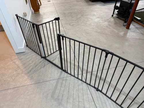
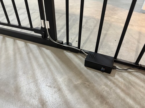
In our basement we have a baby gate, which surprisingly keeps our cat out of the gym and golf sim areas.
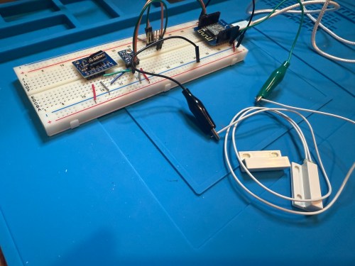
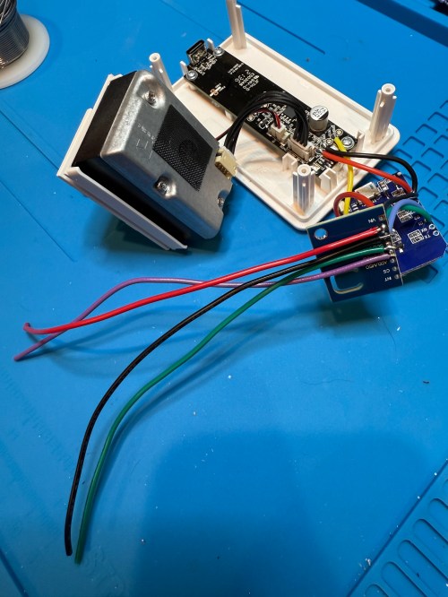
Sometimes we forget to close the gate, so I needed a sensor to monitor its state. I still had the breadboard from the air quality monitor project, so it was quick to add a magnetic door switch and test things out with the D1 Mini clone.
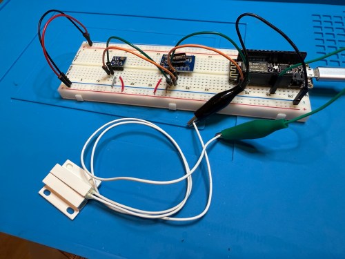
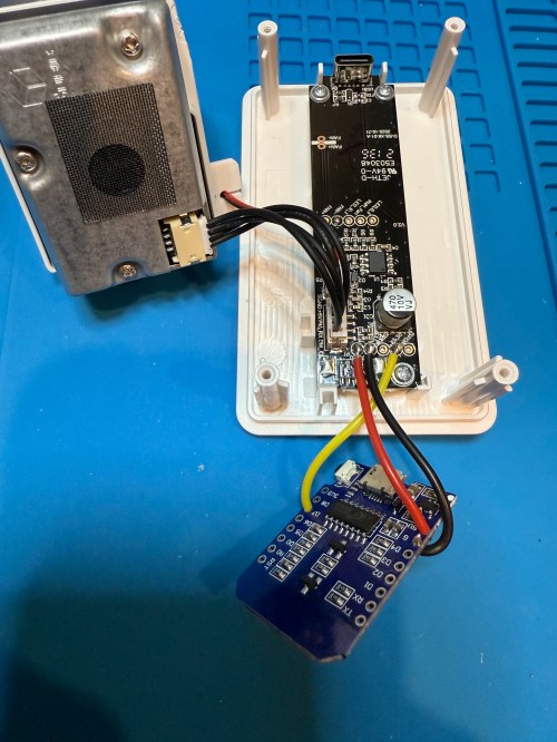
I have extra sensors, so those were kept in the project and allowed me to get rid of the shitty DHT22 I added to the golf remote. Everything worked, but I want to save my last two D1 minis and use them for something with the screens I have for them. So I swapped in an Adafruit Feather HUZZAH ESP8266, which I got with AdaBox 3 or 4 in 2017 and made minor changes to the code.
I figured I might as well use one of the fancy Adafruit Perma-Proto boards I had, which makes soldering all of the connections much easier. As a bonus it was nearly a perfect fit for the case.
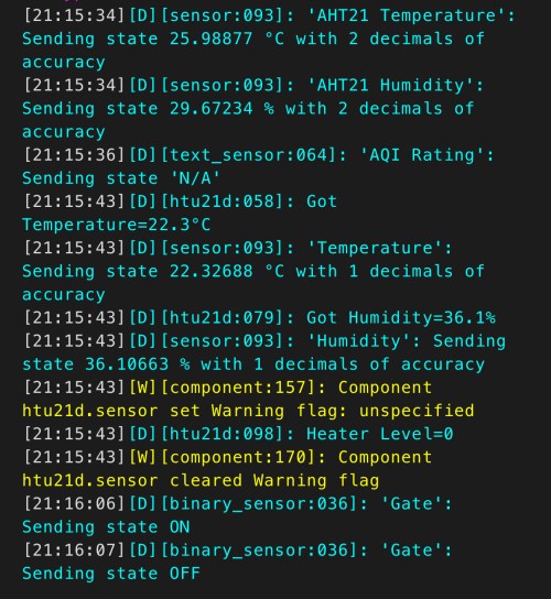
The magnetic switch and Si7021 will live outside the box, so those couldn’t get soldered yet. After connecting power I checked the ESPHome logs to make sure everything was working.
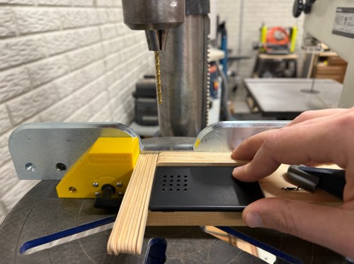
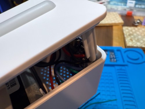
I cut holes in a project box, finished soldering, and used hot glue to secure the board..
I reversed the swing of the gate, placed my device, and attached the two sides of the magnetic switch to the gate.
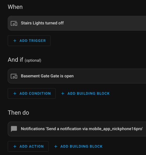
In Home Assistant an automation runs whenever the stairs light is turned off to check the state of the gate. If it’s open, a notification is sent to our phones.
I’m enjoying these little electronics projects, and it feels good to finally put various parts to use.
IKEA recently discontinued Vindriktning, their older air quality monitor.
Inside the device, they put a cubic PM1006K particle sensor. I bought three for $16.95 each last year, because I’d seen people hack them by adding sensors and a Wi-Fi microcontroller to send all of the data to Home Assistant. For my modding I bought:
The YouTube video linked above is a great guide to follow. I didn’t connect wires to the fan or the light sensor since I had no use for them. I also didn’t stack my sensors because I wanted the BME280 to be outside of the enclosure, where it would be less affected by the heat produced by the ENS160 and D1.
Even with the sensor outside of the case, the BME280 still reads high, because it heats itself up. I actually tested different lengths of wires and placements of the sensor before realizing I was still going to have to adjust the data. An ESPHome filter made the adjustment easy, which I did individually for each unit after comparing to a mobile Ecobee thermostat sensor. This is the code from the unit for my shop.
Here is how I’m displaying the data on one of my Home Assistant dashboards.
As I was working on this project I knew I wanted a couple more air quality monitors around the house, which will be finished soon.
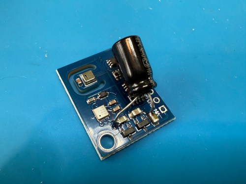
Update: I’ve had to make a small update by adding a 47uF capacitor to each ENS160 board, because they have power issues, causing the reading to stop for periods of time. My boards matched up with the right ones in the picture at that link. Here’s a picture of another ENS160 I modified, since it was a tight squeeze to made the modification on the devices I posted about here with everything already wired up. I also realized I was powering these through the 3V3 pin instead of VIN, so I fixed that.
I’ve also improved the display of the data on my dashboard by using mini-graph-card.
A big part of the planning for our house included Ethernet wiring because I want to hardwire every device I can, saving the Wi-Fi for devices that require it. It’s much easier and cheaper to get everything wired during the build, instead of adding later. I went through several iterations of the plan and in the end I had the electricians do 42 runs of Cat6:
4 jacks in the office
2 jacks in the office closet
2 jacks in the pocket office
2 jacks in the guest bedroom
4 jacks behind the TV
2 jacks in the living room
2 jacks in the dining room
2 jacks in the pantry
2 jacks in the laundry room
4 jacks in the walk in closet
6 jacks in the master bedroom
10 wires to 5 exterior camera locations (1 extra at each location)
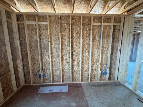
They run it all up through the ceiling. I’m guessing that is to keep it away from most of the electrical. Here’s the master bedroom nightstand wiring as an example.
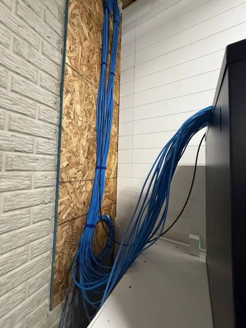
Then all of the cables comes over and down a wall between the laundry room and garage.
Ending at a single location in the basement.
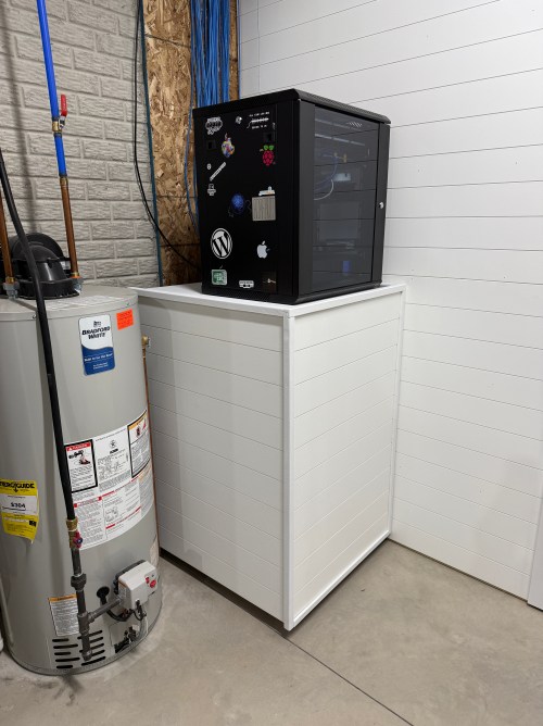
We built a wall (part 1 & 2) and since we moved in back in August I’d had the cable modem and old eero router sitting on top of the network rack filled with new equipment.
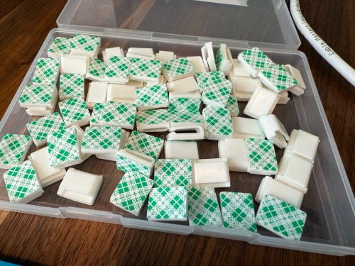
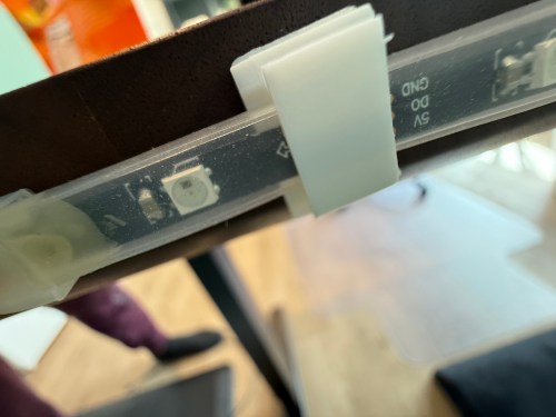
Throughout the house, I put port covers on the unused jacks. Here’s how a wall plate looks with one port open and one covered. The covers will help protect the internals and keep dust out.
What did I buy for my network? A LOT! Here’s all of the stuff for the rack, cables, and tools.
When it came to the actual networking equipment I took a good look at the stuff from Ubiquiti/UniFi. It’s top of the line, which is reflected by the price tag. I decided to go with TP-Link instead, saving a lot of money.
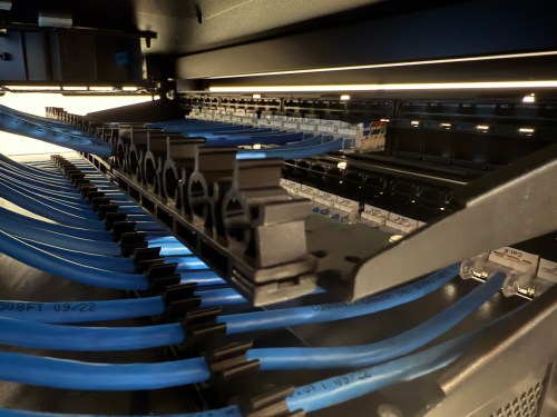
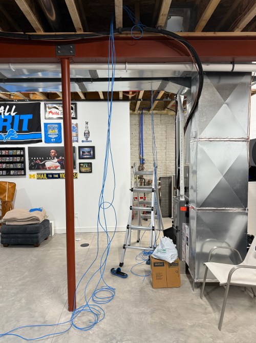
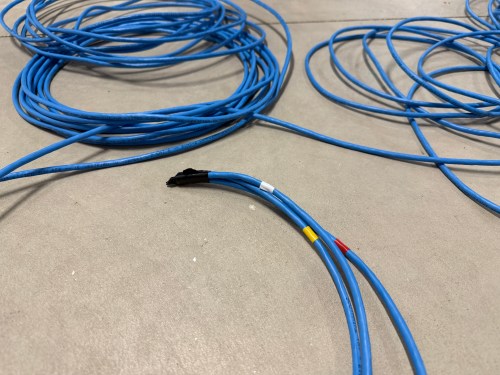
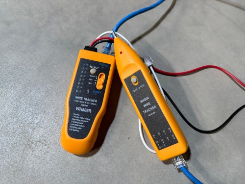
Before I started wiring everything through the rack, I cleaned up the cables.
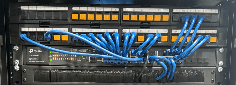
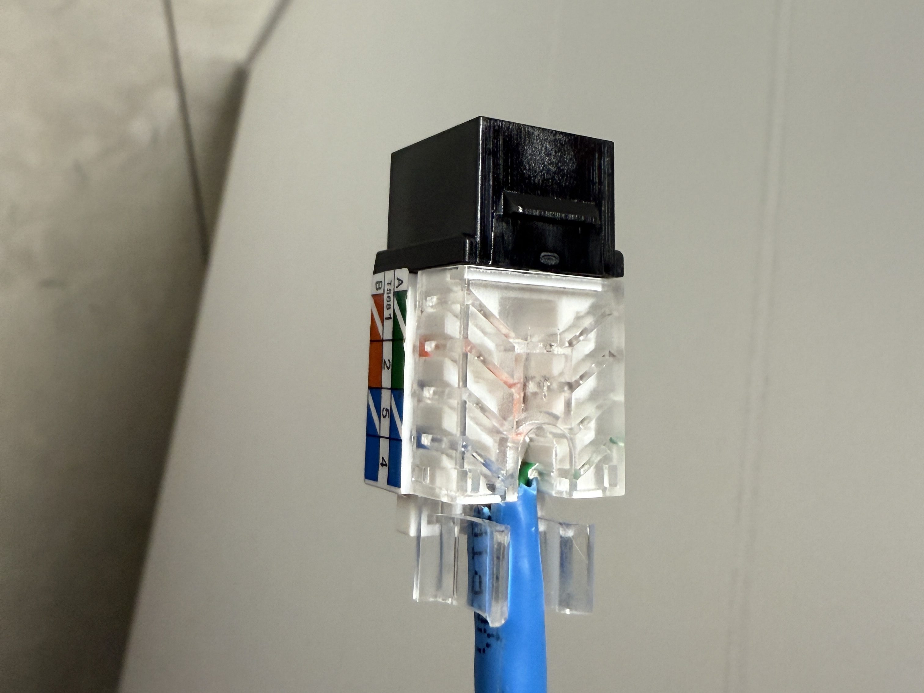
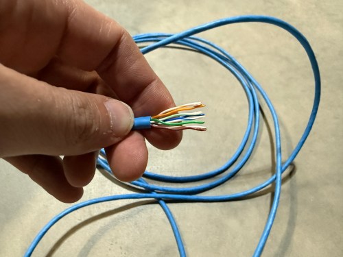
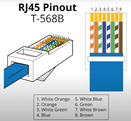
The electricians had done all of the wall jacks throughout the house with the newer T-568B wiring standard, so I followed suit. I learned how to wire the keystone jacks and insert them in to the patch panels.
I’d never done anything like this and it was so much fun. By the end, I was pretty quick with each keystone jack. I highly recommend the Everest 45° ones and the tool for it. The basement needed some Ethernet ports for the golf sim, so I ran four new cables from the rack. I installed a couple of electrical boxes in the ceiling and wired jacks there.
I also needed a custom length Ethernet cable to run from the ceiling jack down to the gaming PC. I’d tried putting RJ45 jacks on the end of an Ethernet cable or two a long time ago and remember it being almost impossible. After watching a quick YouTube video (even though I don’t have pass through connectors), I was able to put both ends on my new cable without a problem and it passed the test.
Then I was able to use patch cables to connect ports on the patch panel to the switch as well as hook up the cable modem, Pi-hole Raspberry Pi, and TP-Link equipment. There’s also a Dell Micro in there, which I’ll cover in a later post about smart home.
When I tried to access the Omada controller I couldn’t bring up the web interface with Chrome on my Mac. After trying a bunch of stuff I checked from my iPhone and it worked. I tried Safari on my Mac which also worked. It turned out I had always prevented Chrome from accessing my local network. I flipped the switch in System Settings and the interface loaded.
At another point I accidentally disabled all of the ports on the switch. The UI splits the switch ports across three pages, and on page two I had clicked the button to select all, unselected a port, and disabled the nine other ports. I quickly realized it disabled 27 of the 28 ports. I was so pissed! Every other UI I’ve ever used will only select the items in view when you click the Select All button, but not the Omada Controller software. In order to get back in I had to access the switch via the USB console, reset the switch to factory settings, and start over.
I’m running four VLANs, named Default, Guest, IoT, and nIoT. IoT is for my Internet of Things (smart home) devices that need to access the Internet and the “n” in nIoT stands for “not” since I don’t want them to access the Internet. The Default and IoT networks are set to get their DNS from my Pi-hole server, which blocks ads and other malicious domains.
Each VLAN has a matching wireless network. The Guest Wi-Fi is set as a guest network, which automatically prevents any device from accessing another. The wireless networks for IoT and nIoT are only set to use the 2.4 GHz band since most of the devices will not work on 5 GHz.
I added mDNS rules for Printers and AirPlay devices from the IoT network to the Default network.
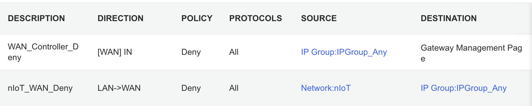
It took me awhile to figure out the ACL rules. I have two for the Gateway. The first prevents any outside IP from accessing my network management page and the second prevents the nIoT network from accessing the Internet.
I ended up with six rules for the switch, since the default behavior of the Omada stuff is to permit everything. With my Pi-hole server on the IoT network I had to allow it’s IP to access anything on the Default network (this should probably be limited to specific ports). I had to allow some ports from the camera IPs to access the Default network and I had to allow some ports from my Home Assistant server to access the Default network. I may find out I need to adjust those ACLs, but more on those smart home aspects in a future post. Then the IoT and nIoT networks are denied from accessing Default and a bi-directional rule prevents the Guest network from accessing any other network.
Seems to be running pretty well. I have some smart home stuff on the network, but haven’t connected any of the light switches yet and have a lot of Home Assistant configuration to do. Originally I didn’t have an access point in the basement, but after a few days realized it was necessary and added one. Here’s a view of the network topology, automatically generated by the Omada controller.
If you upload a floor plan and place walls, the software can even run a wireless coverage simulation. The house has great signal and the yard should get good connections as well.
Power over Ethernet is pretty sweet. It’s so nice not needing power cables for the 10 devices with PoE support.
Time to finish setting up my server and smart home devices. Watch for an upcoming post with all of the details.
I finally bought a doorbell camera when I saw some specials last week. I went with the combination Ring Video Doorbell Pro and Ring Chime Pro, which came with a free 3rd generation Alexa Echo Dot. The Chime is great for the basement, where I can’t always hear the doorbell, especially if I’m using a loud tool. My 2nd generation Alexa Echo Dot moved to the basement as well since I spend so much time in the workshop.
Last year I installed a bunch of Lutron Caséta switches and remotes with dimming functionality. At the time I forgot to test the ceiling fan in my bedroom. So when I went to use it this summer, I got this nice surprise (turn up the sound)…
Ceiling fans don’t like dimmer switches. I’d done a little searching here and there for a smart 3-way switch alternative, but hadn’t been able to find anything. Then one day while walking through Home Depot I noticed some Leviton Decora Smart switches. I did some research when I got home and ordered a DW15S-1BZ and a DD0SR-DLZ. No dimmers on these. Installation was easy and I can use the ceiling fan again. Check out the difference.
I will mention a few negatives with this Leviton switches. The “remote” is wired in, unlike the Caséta remote which can be placed anywhere. It costs a bit more as well. The last thing probably won’t be a big deal for anyone, but it seems like the system is using a relay because I can hear it click back and forth from across the room when I trigger the switch. The clicking may not be the best for a baby’s room.
Other than those things, the Leviton switches work well so far. Check them out if you’re looking for a 3-way switch.