I had no plans for a part 3, but in part 2 of this series, I mentioned how I messed up the wiring several times when I was assembling the module. Instead of fixing it at the time, I started from scratch since I had extra parts. Well, I made some time to disassemble the non-working module and build a new one. I quickly set up a prototype on a breadboard to make sure I didn’t make the same mistakes and then I soldered it all together on a permanent board. Was smooth sailing, even with squeezing everything in as much as I could.
Now I have a two different spare relay modules, depending on power requirements, when I need one for a project.
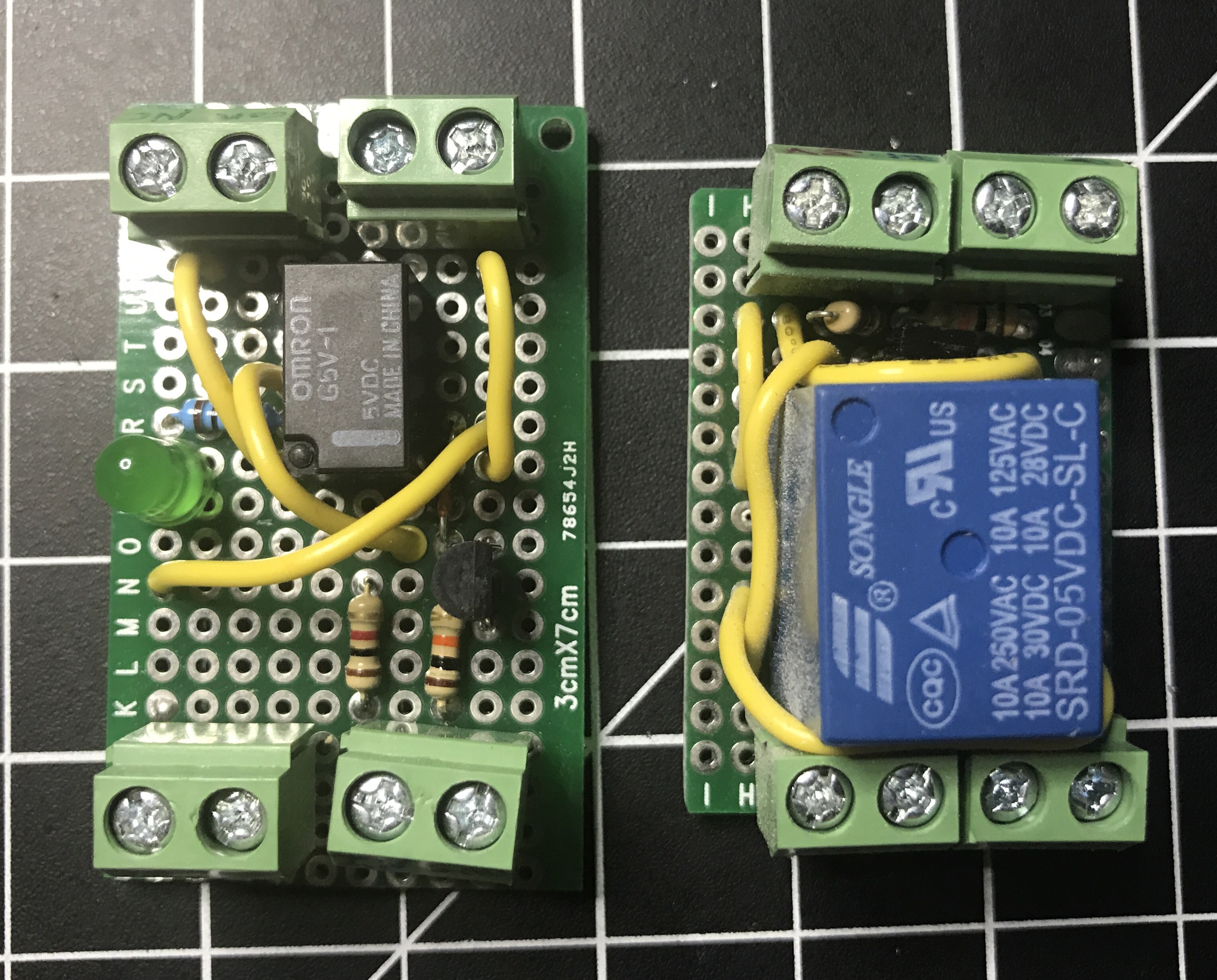
A couple of weeks ago I built a 5v relay module, but realized the relay wasn’t sufficient for my needs. So I had to order a heftier one that could handle more than 0.5 amps of current.
I was under a time crunch and couldn’t wait for a 5 or 10 pack, which had longer shipping times, so I had to go with a set of 2 for $5.99. These are basically the same relays used in all of the manufactured modules you can buy for less than $5, especially if you buy multiple units.
I set up my GoPro overhead and talked through the build process of my new relay module. It was not a smooth process, because I finally messed up my wiring, which I’d been so proud of hitting a 100% success rate on first attempts when putting together circuit boards. I not only messed up, but I realized my mistake, and then fucked it back up after thinking I was right the first time.
I forgot to take any good pictures of the completed relay module this time around, so here is a blurry screenshot I grabbed from the video, showing the original relay module, the non-working version (which I’ll eventually fix up), and my final version. Similar to whenever I screw up and lose a bunch of code, I made it a personal challenge to turn out my best work on the redo. As you can see, my final version saved a lot of space.
Now that I’ve created my own relay modules, I won’t do it again unless I have specific requirements. Buying the same thing already made is a lot more time effective. It was fun and a great learning experience though. Here’s what the wiring diagram looks like spaced out on a breadboard. There isn’t much to it.