I’ve used a couple of online CrossFit programs this year that I’ve really liked. The first is Hybrid Performance Method. For about $35/month you can choose between 8 different programs and you can switch anytime you want with a few clicks in your profile. For a few months at the beginning of the year, a couple of friends and I were following the Hybrid WOD program to prepare for the CrossFit Open. It was hands down the hardest, but also the best programming I’ve followed. We averaged about 90 minutes in the gym, 5 days a week and saw big improvements in our fitness.
After I tweaked my back, I switched over to Hybrid Push-Only, which is all about the upper body and runs 4 days a week. It rarely takes me over an hour to finish the assigned work. I’m really loving it. Bench press is the main lift, but there is also a fair amount of overhead pressing, a ton of accessory work, and a day focused on pulling strength, mainly pull-up type movements. We’ll see if I can’t hit a 300 pound bench press at the end of 12 week program. I’ve been spacing out the 4 days a week so I can still go to a 2-3 CrossFit classes. I think I’m averaging about 9 days to get through a week of the program and am finishing up week 8.
The other program I’ve used this year is Performance Plus Programming. It’s focused around gymnastics type stuff and using movements to create stability and support. It runs $20/month, has 4 workouts per week, and almost never takes me more than 10 minutes to complete. The first month was focused on shoulders, which paired up really well with the Push-Only program. I need to loop back around and repeat that month of programming before I try out the core focused month.
I picked up a 10 pack of these 7 segment red LED displays for less than $5. Since each display requires connecting to a minimum of 8 of the 10 pins (9 if using the decimal point), they aren’t exactly easy to work with. Sure, you can buy these where 2 or 4 displays are already connected in a nice package, controlled with the help of an integrated circuit, but where is the fun in that?
If you need to use more than 1 or 2 displays (at 8-9 pins per display), you’ll quickly run out of pins on your microcontroller or Raspberry Pi. The most common way to work with several of these displays is called multiplexing. It’s a method where you briefly turn on one display, turn it off, turn on the next one, and turn it off. You repeat this through all of your displays and then start over. If you do this fast enough, the human eye thinks all of the displays are on at once. It’s pretty slick!
The advantages of multiplexing are:
Fewer wires/pins needed to drive the displays.
Lower power consumption since the LEDs on only one display are lit.
Seven of the pins on one of these displays match up to the 7 segments (labeled a through g), one pin is for the decimal point (DP), and the two remaining pins can be used for the common cathode (cc), though you only need to connect one or the other. Over to the right you can see how all of the pins and LED segments are arranged. Pretty straight forward.
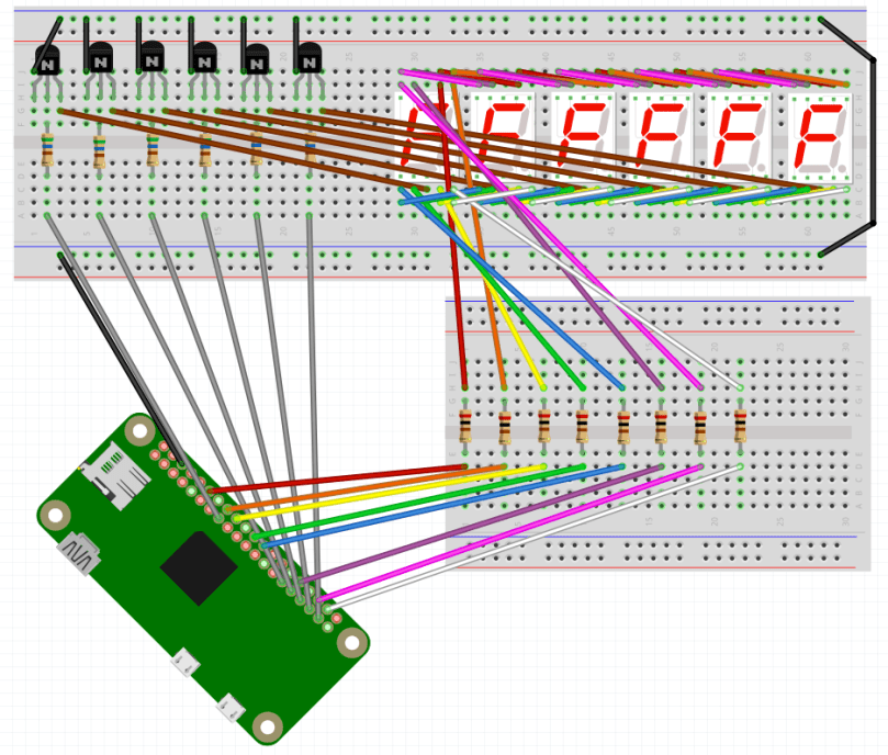
I’m using 6 of these displays in a project, so I needed a lot of wires. It got complex and tangled in a hurry, but amazingly, I connected all the wires without a single mistake on my first try. 🙂 For the most part, I based my circuit design off of this schematic…
Image source: circuitstoday.comThe end result is something like the Fritzing screenshot below. With so many wires overlapping, it’s not easy to see what’s really going on here. I suggest grabbing wiring.fzz from my GitHub repo and playing around with it in the Fritzing app.
When I went to write my proof of concept code, I decided to use the Gpiozero Python library to simplify working with the LEDs. The library allowed me to set up a couple of arrays for the LED segments and the 6 digits (displays)…
segment_leds = []
for i in range( len( segment_pins ) ) :
segment_leds.append( LED( segment_pins[i] ) )

digits = []
for i in range( len( digit_pins ) ) :
digits.append( LED( digit_pins[i] ) )
Then I could easily loop through and toggle the LEDs in a display as necessary…
for i in range( len( digits ) ) :
for j in range( 7 ) :
if ( numbers[ digit_values[i] ][j] ) :
segment_leds[j].on()
else :
segment_leds[j].off()
To make sure things worked I count up from 999000 and then start back at 000000 after hitting 999999. You can see the full code on GitHub.
Now for some visual proof that I actually got it all working! Here it is running when I keep one digit lit for 5/10,000th of a second before turning it off and lighting the next digit.
You’d never know that only one digit is turned on at a time, would you?
If I change from 0.0005 to 0.05 of a second you can start to see that only one display is on at any point in time.
You may also notice it’s counting up a low slower due to the way this code increments the counter. Don’t worry about that.
When I keep each digit turned on for half of a second you can really see how this works.
An issue I’m running into on a Pi Zero is when the processor gets busy doing other tasks, there is a bit of flicker across the displays. You can see this a couple of seconds in to the first video. I’m guessing the code would perform much better on a Raspberry Pi 3B. For my project it’s not a concern, but I want to mention it in case you follow this for your own project. You may also pick up what looks like random flickering of a single digit here and there but that’s due to video timing; the human eye doesn’t see any of that when it’s in front of you.
If necessary, you can take multiplexing a step further and only light up an individual LED on each display at a time, with a method called charlieplexing. It will use even less power, but due to the speed at which you need to switch from one LED to the next, especially across an array of multiple displays, you lose brightness to the human eye.
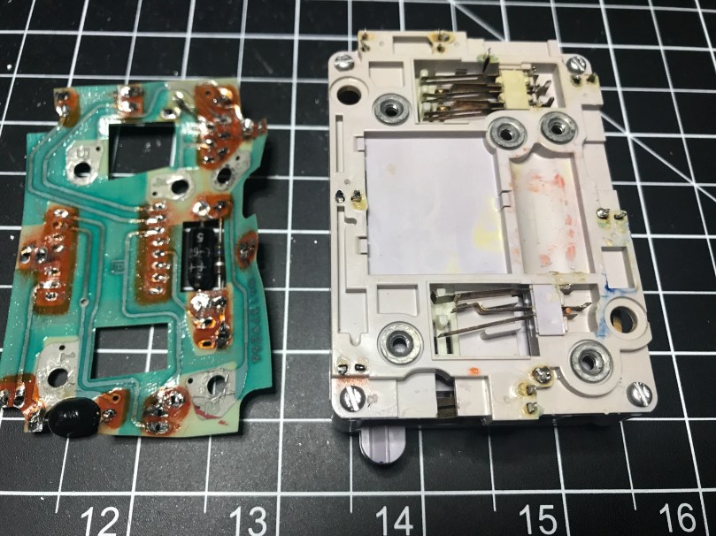
Go back and read Part 1 if you want to the full story on this little project. I did decide to get rid of the PCB on the old phone keypad. Good thing I’ve been getting a lot of desoldering practice. In order to remove the PCB, I first had to remove the wires I had added to the column and row contact points. That was easy and getting the PCB off was a pretty smooth process as well.
PCB and new look of the back side of the keypad.Other side of the PCB. The white rectangle is the back of the 557D IC.
Now that I didn’t have the PCB to carry power and ground around everywhere, I had to solder in my own wires. I also had to solder back in all of my connection points to provide the outputs I’d feed into a microcontroller (I used an Adafruit Feather 32u4 Basic Proto).
Once all of the wires were in place and then connected to my microcontroller I wasn’t getting expected results from a simple little program I wrote to display the values. Took far too long for me to remember I needed to use pull down resistors to prevent floating values. I put 10k Ω resistors in each of the circuits…
Prototyping with pull down resistors.
Output from the pins couldn’t get any better…
I loaded an example from the Arduino KeyPad library, which gave me very weird behavior. After looking at the underlying code, I realized it wanted the outputs of the keypad to be HIGH when a key was not pressed and LOW when it was. Well, my circuit was doing the opposite, so I had to have to invert everything. I didn’t have any inverter ICs, so I used NPN transistors to create an inverter circuit on each output.
Prototyping by inverting the output of the keypad column and row values.
Progress. Now I was able to get the library to correctly recognize some key presses. 95% of the time it seemed to think everything was coming from column 1 (1, 4, 7, *) though. The library comes with a MultiKey example. When I ran that, it was reporting every key on the row as being pressed. WTF?!
For the life of me I could not figure out what caused this. I checked wires, measured voltages, did continuity tests, resoldered connections, changed boards, used different GPIO pins, and countless other things. Nothing made a difference. My own code was working beautifully though. Eventually I gave up on the library. It wasn’t worth the effort and I was out of ideas.
Update: Later on I went back and read the KeyPad library code again because it was bugging me. Turns out these keypads don’t actively read the column pins like they do the row pins. My assumptions about how they worked was very wrong because I hadn’t read far enough into the code before. When checking for key presses, typical keypads iterate through the columns to send a pulse which feeds over in to the rows, which are then read in. How a Key Matrix Works has a pretty good explanation with visuals. If I get my hands on another similar keypad maybe I’ll try to recreate this functionality.
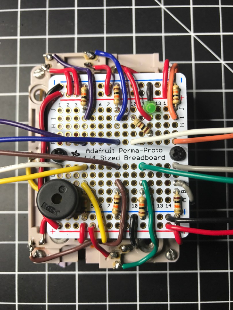
I rewired everything to use the pull down resistors again (video of soldering). A huge benefit of the decision was it drastically simplified my circuitry. This would save me 49 solder points! I probably would have needed to use a half-size perma-proto board instead of the 1/4 size I ended up using.
I decided to put in a piezo buzzer to add sounds. I also used a tiny LED, which I had salvaged from some old computer speakers, to show when power is switched on to the backlight.
The finished board. Isn’t it a thing of beauty?
Side view before bending the output wires off to the sides.
I tried a couple of different methods of producing touch tones (DTMF) to match up with each key, but with the microcontroller I’m using and the small piezo buzzer, the sound was terrible. I would need something a little more capable I think.
Here’s a demo video.
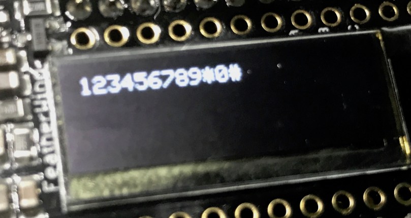
Hard to see the OLED screen in the video, but I was only using it to output each key press. Something like this…
I even went out of my comfort zone and did a quick share of this on Adafruit’s Show and Tell. If the video doesn’t start at the right spot you can skip ahead to the 12:42 mark. Going back to watch, my demo kind of sucked since it’s hard to hold something up to the Mac camera and push buttons at the same time.
Update: Continue on to Part 3, where I create a matrix of buttons to act as a keypad.
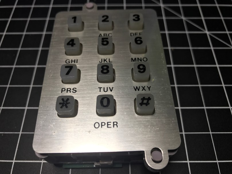
I’ve been on a kick tearing apart electronics. In addition to the switch I got a bunch of parts from, I’ve tore into a lamp and some old computer speakers. When I found an old telephone (it has a date of 5/30/1980 printed on it!) in my basement I knew I had to see what was inside. The previous owners left it in a storage room and I have no idea why I never pitched it. I didn’t take a picture before taking a screwdriver to it, but it looked exactly like the photo on the right.
People have been hacking phones for a long time. Perhaps the earliest and most well-known was the Steves (Jobs and Wozniak) using a blue box on payphones. I’m nowhere near that level, but you have to start somewhere right? I pulled the ringer, speaker, and microphone out of it. I haven’t messed with these yet.
A lot of parts were extremely dirty.
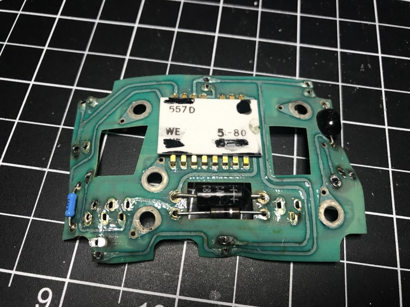
The part I thought would be neat to work with was this keypad.
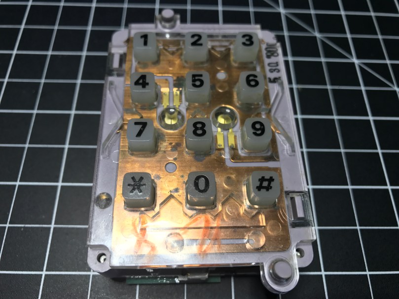
With the faceplate removed you can see the date stamp in the upper right.Back side.
It was a bit of a process figuring out how to tap into this thing. Eventually I realized what these contact switches on the sides were for.
There are seven of them. The top has two and the bottom has one, which correspond to the 3 columns of keys on the grid. Then the left and right sides each have 2, which match up with the 4 rows of keys.
I figured out I could solder wires to the contacts points connected to each of those switches. I was in! From the way the keypad was connected to the rest of the phones circuitry I knew the screws were an important piece to tie it all back into the entire system. After some trial and error I determined which screws should be used for power (red wire) and ground (black) in order to get useable data out of the 7 switch contact points. The other 3 screws also connect to power. I was using alligator clips on those, but disconnected them for the picture.
Something isn’t quite right about the screw connections though. When I connect them the opposite way, flopping to have 1 power and 4 grounds, the backlight on the keypad works, but the readings from the soldered contact points are useless. With them connected this way, I don’t get the backlight, but I get data I can make sense of. There is probably something obvious I’m missing about how this all works together.
Unfortunately for me, the output from the contact points isn’t digital (limited to on/off), so I couldn’t use the Arduino library. It would have made things so much easier. It’s not surprising though, since this piece of technology is almost 40 years old!
I was able to get some code mostly working. Detecting the column of a button press was pretty straight forward and works great. Rows detection is another story. I’m reading in analog values and using sampling along with standard deviations to determine which row’s value is unlike the others. Well, the first row always reads a pretty high value, when a key on any row is pressed. The values for the other rows fluctuate as expected. When that first row is high, I’ve attempted to also look for a high value from another row, but it triggers the wrong row too often.
Demo time…
Even making this short little video, which took at least 5 takes, there was a false trigger for pressing 1 and many key presses not being recognized. Not useable.
I have a hunch the screw connections are responsible, at least in some part, for sending DTMF signals, also known as Touch-Tone. I don’t really care to get in the business of decoding these. This is precisely why I was hoping I could detect useful output from each of the row and column contact points.
I pulled apart the unit even more and discovered a Western Electric 557D is the brains of the operation, but it’s so old there doesn’t seem to be a datasheet online for it. What I’m going to do is remove the PCB and wire up everything on my own. Then I can easily get on/off as digital values from the columns and rows and make sure the backlight works. Stay tuned…
Remember last week’s post about tearing apart a component switch to repurpose parts? I spent some time fooling around with IR after that. I thought it would be neat to recreate the basic functionality of switching between 3 devices. For my proof of concept the devices were simple the 3 status LEDs, but you can imagine the possibilities of turning on different devices or triggering processes run on a computer.
The new microcontroller I got is one I posted about a few months ago, called Puck.js. It has an IR transmitter built-in, so I wanted to use it to mimic a remote. Puck.js is pretty slick. It’s really neat being able to program a device in Javascript through a web IDE over Bluetooth Low Energy. No wires at all!
Propping a component into the GPIO pins like the author did doesn’t work for shit. You can’t get a solid electrical connection, especially if you bump it at all.
I kept getting Out of Memory errors on the device because the array would get really large really soon.
My next thought was to wire up to one of my other microcontroller that run Arduino, but the popular IR Library (IRLib2) doesn’t support the chips used in any of the boards I have. So over to a Raspberry Pi Zero. Pretty much every search result mentioned using Linux Infrared Remote Control (LIRC). May of the setup instructions I found were incomplete, but I was able to get things running by taking pieces from these two sites:
I’ll detail the steps that worked for me. Before I go down the software route though, I wanted to make sure the IR sensor worked. The only markings on the component are “71M4” and I have been unable to find a datasheet anywhere to match. Luckily these IR receivers are pretty standard and I had a pretty good idea of the pins from looking at how it was connected in the old device. I got the idea of hooking up a simple LED test circuit on the data pin from an Adafruit learn guide. Pin 1 is data, going into a GPIO pin on the Raspberry Pi (26 in my case), pin 2 is ground, and pin 3 is power (VCC). You may want to use the 3.3V pin on the Pi to provide your power instead of 5V just to be safe, or consult the datasheet for the IR sensor you’re using. Connect the anode of the LED to power and the cathode to pin 1 of the sensor using a 220 Ω (I used 200) resistor. When you press buttons on an IR remote, the sensor will send data through pin 1 and the LED will light up. Here’s a Fritzing wiring diagram for this test as well.
My test was successful! Now I was able to move on with some confidence knowing the part worked.
Install LIRC:
sudo apt-get update
sudo apt-get install lirc
Edit the /etc/modules file:
sudo nano /etc/modules
Add to the end:
lirc_dev
lirc_rpi gpio_in_pin=26
Change the pin if you’re using something other than 26. If you’re also going to do IR transmitting, you can add a space and gpio_in_pin=22 on that last line.
Press Ctrl + X, hit Y to say you want to save, and then Enter.
Edit the /etc/lirc/hardware.conf file:
sudo nano /etc/lirc/hardware.conf
Look for the DRIVER, DEVICE, and MODULES settings. Set them to match:
Press Ctrl + X, hit Y to say you want to save, and then Enter.
Edit your /boot/config.txt file:
sudo nano /boot/config.txt
Look for this line:
# Uncomment this to enable the lirc-rpi module
If you see it, remove the # from the next line and edit it to look like this (if your file doesn’t have it, add this to the end of the file):
dtoverlay=lirc-rpi,gpio_in_pin=26
If you’re going to do transmitting, also add this to the same line:
,gpio_out_pin=22
Change both pins to match whatever you’re using. Press Ctrl + X, hit Y to say you want to save, and then Enter.
Reboot your Pi:
sudo reboot
Now it’s time to use LIRC to record the codes sent by whatever remote you’re using. First you’ll want to see names you want to give your buttons. Run:
irrecord --list-namespace
Scroll through the list and make notes on all of the codes you want to use for your buttons. You’ll need the codes in a bit. Here was my list:
KEY_POWER
KEY_1
KEY_2
KEY_3
Stop LIRC:
sudo /etc/init.d/lirc stop
Use irrecord to create a configuration file for your remote. Follow the instructions carefully that come up on your screen. This took me several minutes for my remote with only 4 buttons.
Note: When it says Please enter the name for the next button (press to finish recording) is when you’ll need those codes above.
irrecord -d /dev/lirc0 ~/lircd.conf
When finished you’ll have a new file in your home directory. Take a look at it:
cat ~/lircd.conf
Mine looked like:
begin remote

  name  /home/pi/lircd.conf
  bits           16
  flags SPACE_ENC|CONST_LENGTH
  eps            30
  aeps          100

  header       9004  4474
  one           580  1666
  zero          580   542
  ptrail        578
  repeat       9006  2229
  pre_data_bits   16
  pre_data       0x61D6
  gap          107888
  toggle_bit_mask 0x0

      begin codes
          KEY_POWER                0x7887
          KEY_1                    0x40BF
          KEY_2                    0x609F
          KEY_3                    0x10EF
      end codes

end remote
Make a backup of the default LIRC configuration file:
You need to set up each button similar to what mine looks like:
begin
  remote = *
  button = KEY_POWER
  prog = pylirc
  config = KEY_POWER
end

begin
  remote = *
  button = KEY_1
  prog = pylirc
  config = KEY_1
end

begin
  remote = *
  button = KEY_2
  prog = pylirc
  config = KEY_2
end

begin
  remote = *
  button = KEY_3
  prog = pylirc
  config = KEY_3
end
Do a simple copy/paste and change the button and config for each entry.
Press Ctrl + X, hit Y to say you want to save, and then Enter.
Create a basic Python test program:
nano pylirc-test.py
Paste in:
#!/usr/bin/python

import pylirc

pylirc.init( 'pylirc', './pylirc.conf', 0 )

while ( True ) :
	s = pylirc.nextcode( 1 )
	command = None
	if ( s ) :
		for ( code ) in s :
			print( code["config"] )
Press Ctrl + X, hit Y to say you want to save, and then Enter.
Run the program:
python pylirc-test.py
Press buttons on your remote and if everything is working you’ll see the special name codes being output for each button you press.
Hit Ctrl + C to stop the program.
I already had all of the logic written for the buttons to work and switch LEDs, so it was easy to add in a little more code to take action when the appropriate IR codes were received.
Once I found the correct information, setup on the Pi was quite easy. A lot of steps, but easy stuff. Making the Puck.js duplicate my Infrared remote’s codes was a bit of a challenge. From the Puck.js Infrared tutorial I linked at the beginning I knew I needed to have an array of pulse lengths, but I didn’t have anything like that from the LIRC configuration. All I had was some hex values for each code:
KEY_POWER: 0x7887
KEY_1: 0x40BF
KEY_2: 0x609F
KEY_3: 0x10EF
Combined with another hex code for pre_data (0x61D6) from the lircd.conf file, I had more complete codes:
Infrared remote control signals from the LIRC remote configurations project, converted to Pronto Hex and Protocol, Device, Subdevice, and Function using lirc2xml…
BINGO! It had the Pronto Hex codes. I cloned the repo and started searching for my hex values. I found power, 1, and 2 matched up with codes used by something called a gigabyte TV. I plugged the codes into a program and they worked! I was only missed the code for button 3.
Then I spend way too much time still searching around. I knew enough about how IR worked and had 3 codes. I finally realized I should be able to figure out what changes to make in order to get my 4th and final code. I converted the hex values to binary:
KEY_POWER: 0x7887 = 111100010000111
KEY_1: 0x40BF = 100000010111111
KEY_2: 0x609F = 110000010011111
KEY_3: 0x10EF = 001000011101111
Then I started looking at the end of each array of Pronto Hex codes, because every code uses the same pre_data. I quickly determined an ON bit (1) was 003e, OFF (0) was 0013, and they were separated by 0017. I made the necessary adjustments and had all 4 buttons working with IR!
This IR journey turned out to be quite an adventure. I learned a lot, which was the point. My infrared-3-input-selector project on GitHub has the Python program used in the demo video, my pylirc config file, the simple pylinc test program, the Puck.js code, and even an Arduino sketch with the button and LED logic I created initially before realizing I needed to switch to the Raspberry Pi.
Developers often have strong opinions about their environment and habits, such as the debate about tabs vesus spaces. I recently realized I prefer certain types of themes or color schemes for my software, depending on the type of activity.
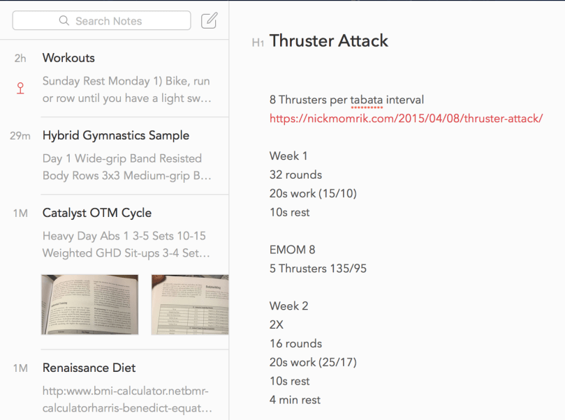
For straight up writing, like blog posts or notes, I prefer a light theme.
The first program I remember “writing” was on a TRS-80 connected to a TV for the display and a cassette tape recorder for the disk drive. The language used was BASIC. I did nothing more than copy the code out of a book. It made bars of different color appear on the screen. Fancy stuff! I was probably 8-10 years old if I had to guess.
I don’t remember touching a computer much after that until we had WordPerfect, the Oregon Trail, and Where in the World is Carmen Sandiego in one of my middle school classes. I did try writing a few choose your adventure type things on a TI-86 calculator in high school, though I mostly used it to store formulas and notes for cheating on tests.
I didn’t really get into writing code until I switched my major from Accounting to Computer Science in the first month of college. I wish I’d been more interested in those earlier years.
Everybody in this country should learn how to program a computer… because it teaches you how to think.
–Steve Jobs
While browsing at Toys”R”Us to buy gifts for my nieces, I prefer to find something in the learning or creative sections because they get plenty of toys from everyone else. My mom had picked up a book of mazes for me to get Kennedy (6), because she’d been really into them lately. When I saw the Code & Go™ Robot Mouse Activity Set I was excited and didn’t hesitate to put it in my shopping cart.
Today I sat down with Kennedy and showed her how it worked. It took her a few mazes to get the hang of separating steps, but before long she had the hang of it and was even able to do her own form of debugging when there was a mistake. Here she is programming and testing card 9 after planning it out. I think this was the first one she did on her first attempt.
Like any good programmer, by card #16 she wanted to do away the planning stage and directly input her program. It worked out, but the 17th maze was long and complex. After having to start from scratch three times, she realized the planning stage was useful.We played for over 3 straight hours! After finishing all 20 cards, it was time to design her own mazes.
Yesterday I had introduced her to ScratchJr on the iPad.
With ScratchJr, young children (ages 5-7) can program their own interactive stories and games. In the process, they learn to solve problems, design projects, and express themselves creatively on the computer.
I showed her around the app and she seemed to be having fun. I’m curious to see if she’ll use the app on her own and start building stories.
I think it’s a shame programming isn’t a core class in schools yet. It opens so many doors and will only be getting more important. Writing code and making a computer do what you want makes math fun and really does teach you how to think because you have to break things down and learn about logic.
Unfortunately many adults think it’s too late to learn to write code. It’s not.
The first thing many of us write in a computer language is called a Hello World program because the goal is simply to make the words “Hello World” display on the screen. Browse through Hello World Programs in 300 Programming Languages to see how simple many of them are.
I decided to create a game I could play with my 6-year-old niece over the holiday weekend. To get her involved I wanted to have some configuration options. I came up with a dice game, similar to the card game War, because it’s very basic and easy to understand for a young kid. I got a good start on Saturday night and had a fully functional version by lunch on Sunday. I’m calling it War of Dice.
I made a little demo video to show how it works. The focus kind of sucks, but I wasn’t recording a 4th take. Not sure if the brightness of the LEDs was causing an issue with the GoPro or it was too close for my camera settings.
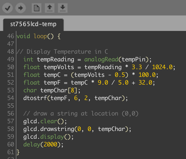
There have definitely been some frustrations through this whole learning process and working inside the Arduino IDE, which uses C. I learned how to code using C++ (we didn’t use any Visual) in college, almost 20 years ago! Probably haven’t touched C since though. I guess what’s old is new again.


 I’ve been on a kick tearing apart electronics. In addition to


 There are seven of them. The top has two and the bottom has one, which correspond to the 3 columns of keys on the grid. Then the left and right sides each have 2, which match up with the 4 rows of keys.
 I got
I got