A Larger Drill Press Table with a Motor

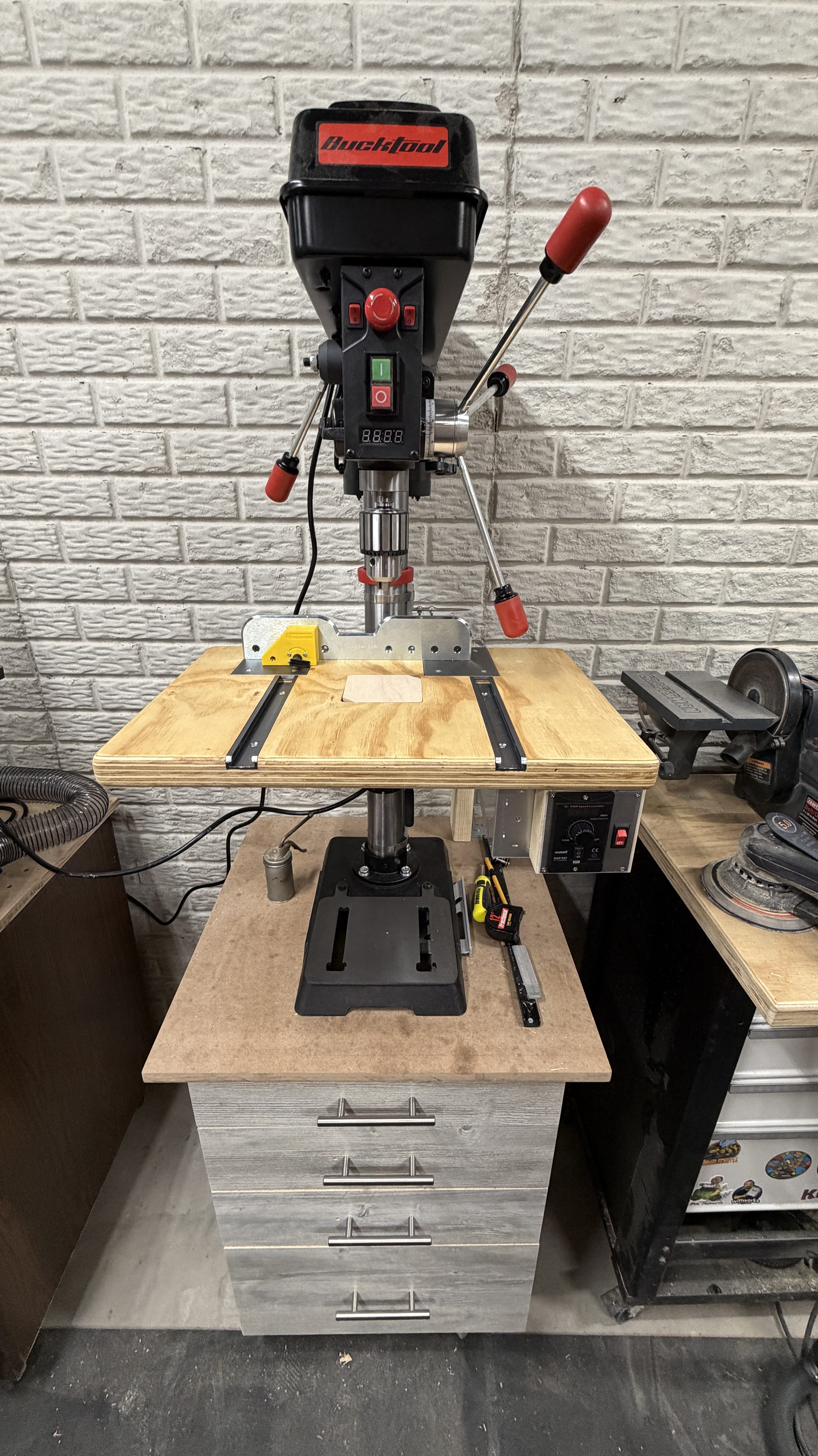
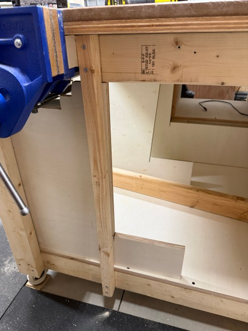
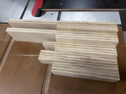
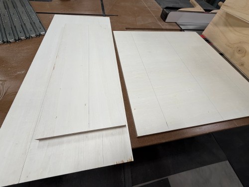
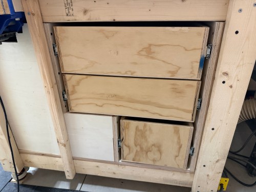
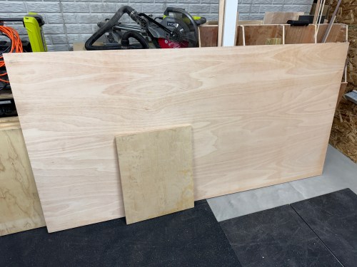
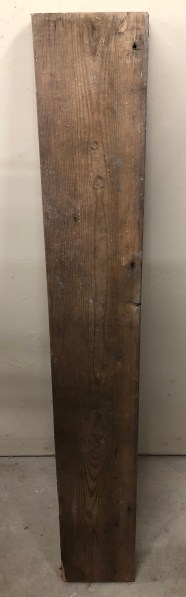
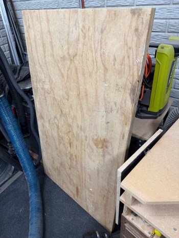
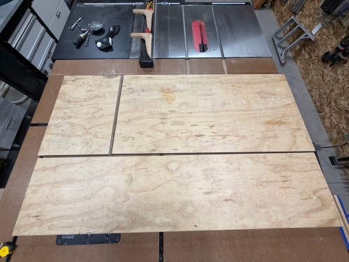
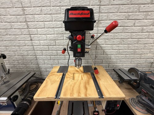
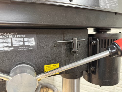
The table on my new Bucktool drill press is about 9-1/2 inches square, which is too small. I set out to make something bigger. First, a side quest though. I still had the top from my old work table, which was two sheets of 3/4″ plywood glued together.

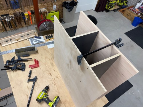
A big chunk was going to the sanding station, which had sheet metal over junk MDF for the top. The brackets holding it to the metal frame were always getting pulled out.

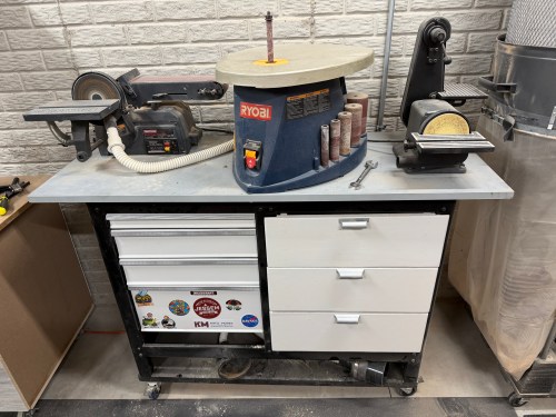
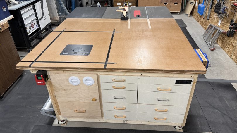
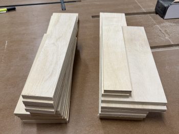
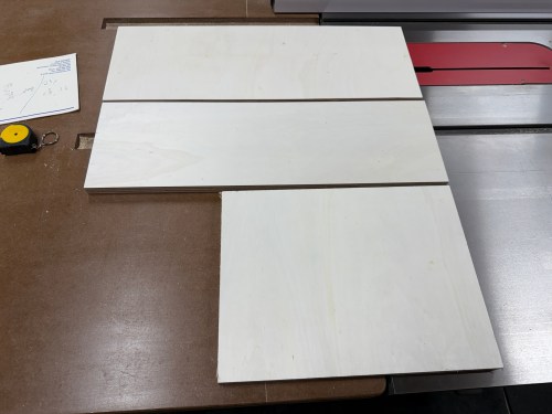
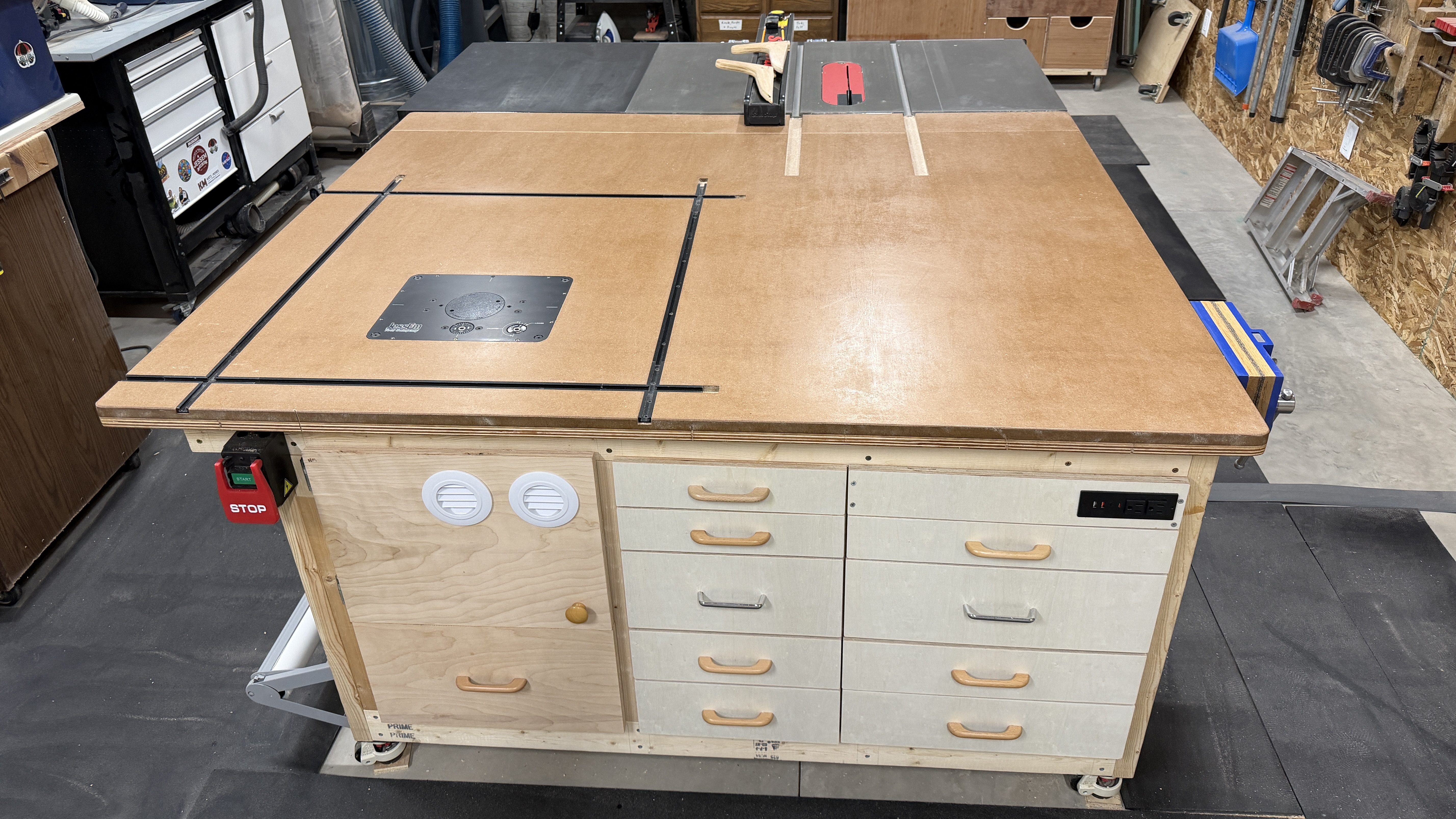
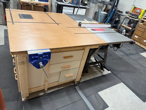
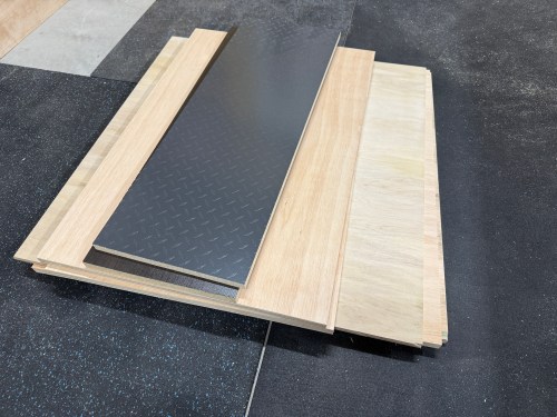
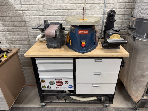
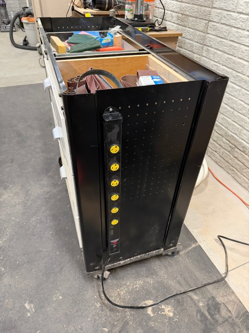
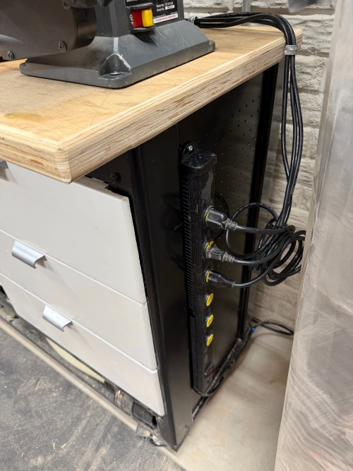
I cut up the plywood lamination and rounded the corners and edges. I changed the orientation of the machines to give me easier access to the big belt sander, which saved about 10″ of width. I also mounted a power strip.

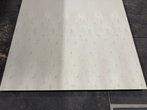
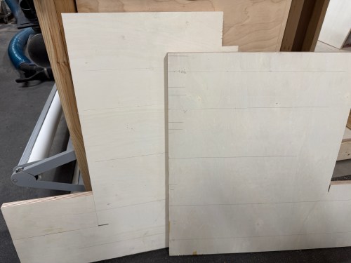
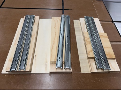
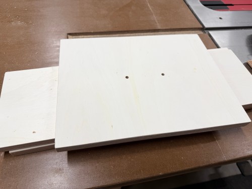
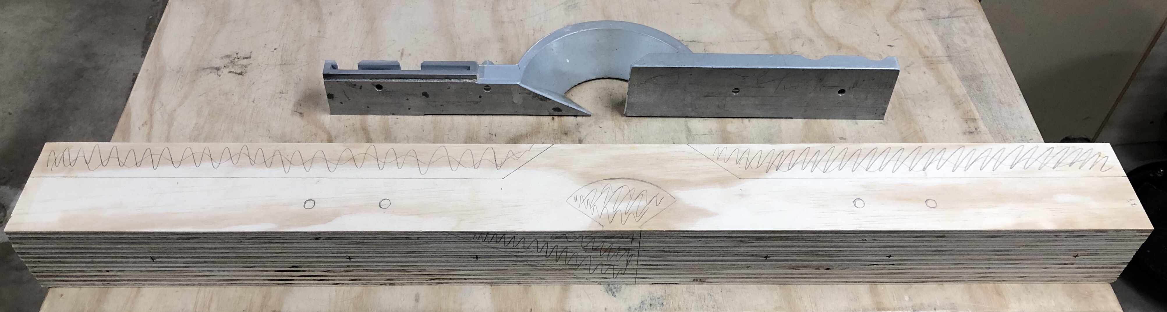
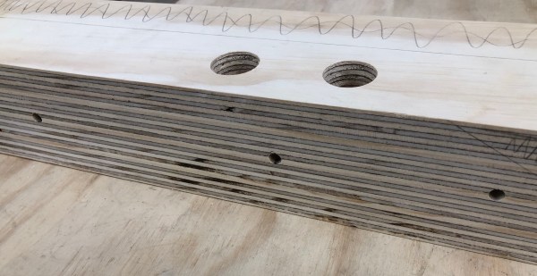
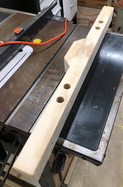
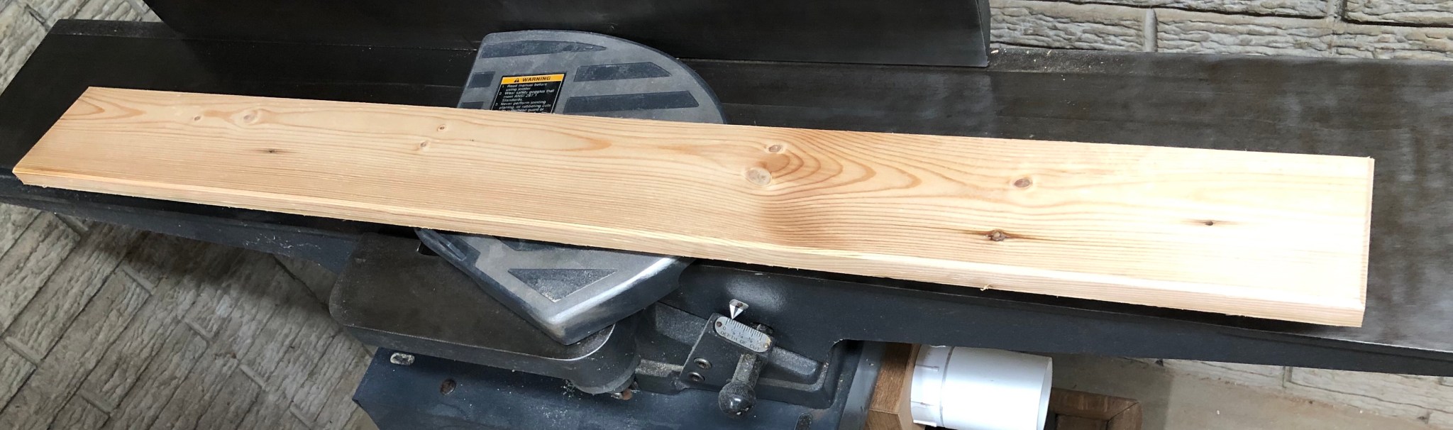
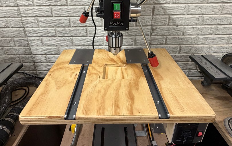
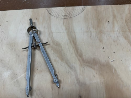
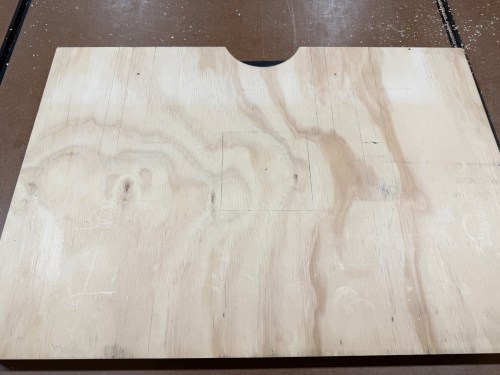
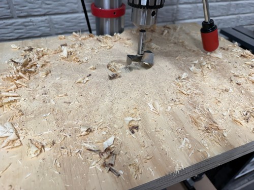
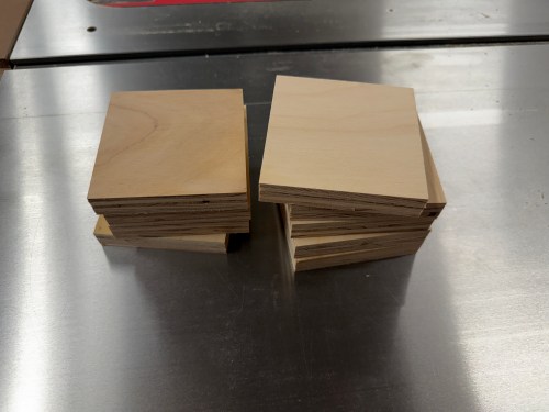
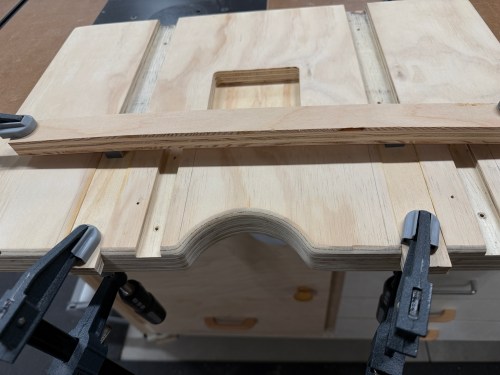
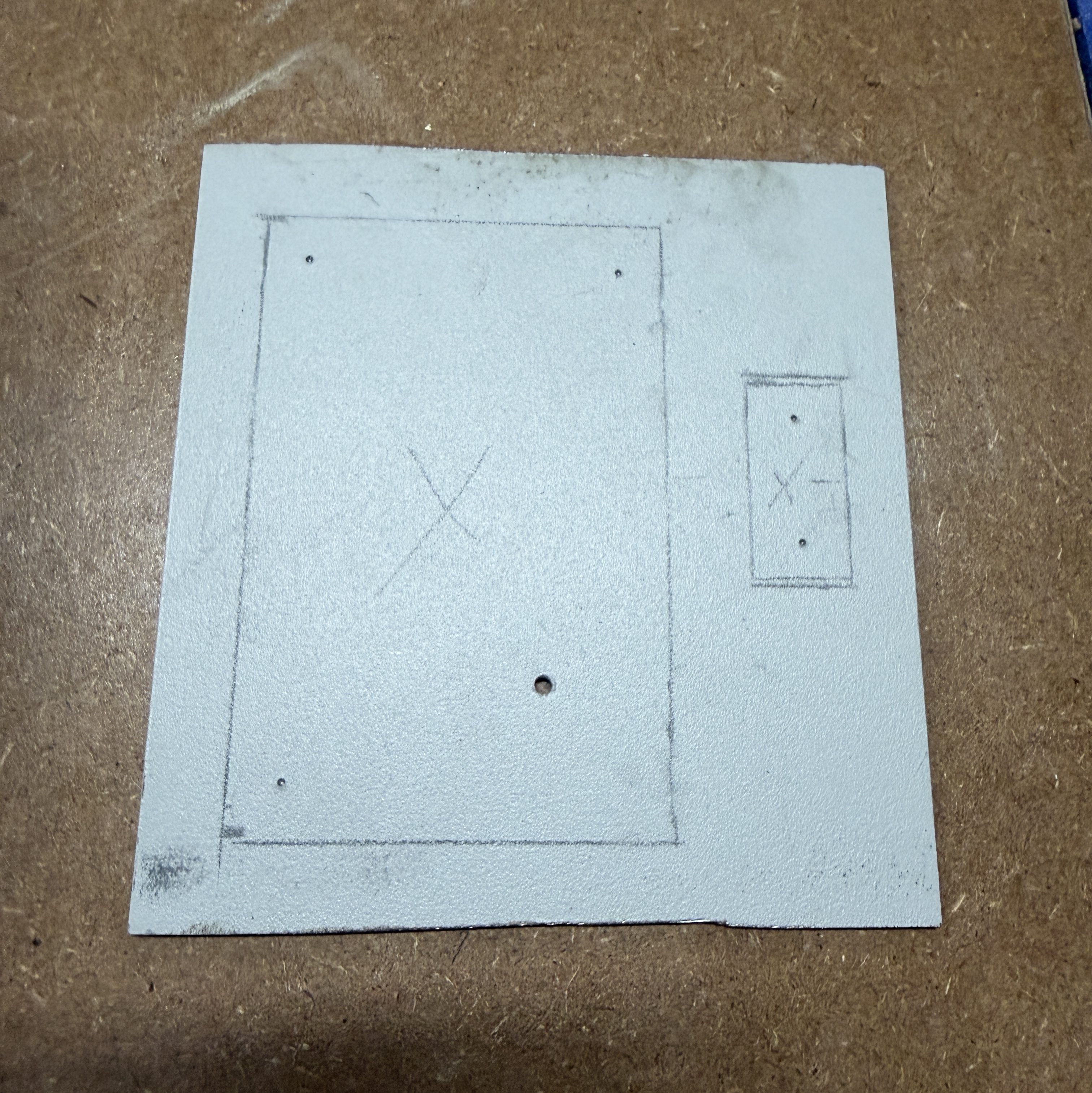
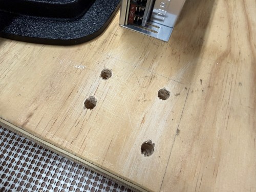
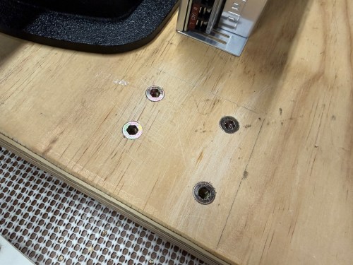
The small chunk of plywood was for a new drill press table. I worked on the layout, routed the middle for inserts, and routed slots.

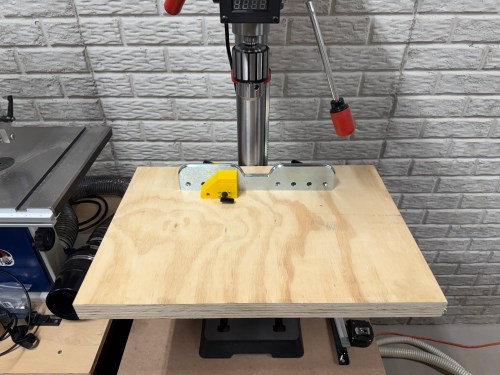
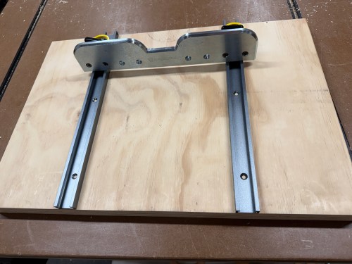
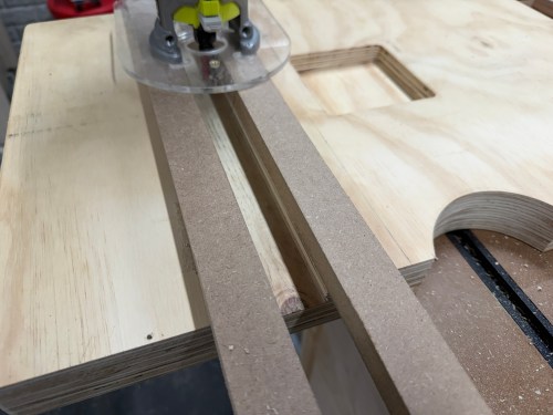
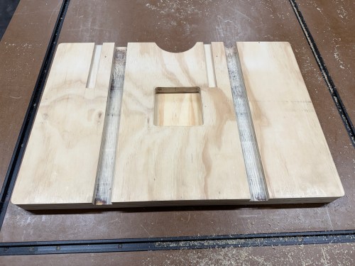
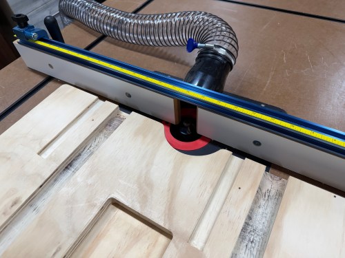
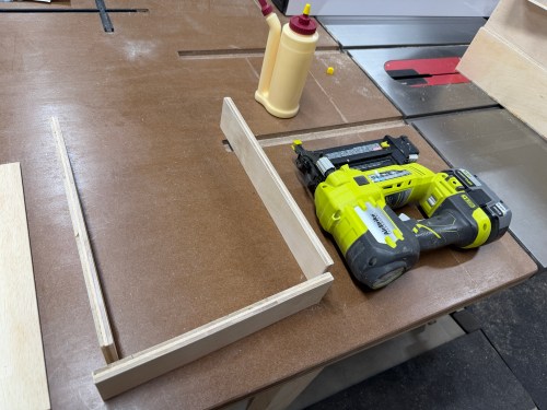
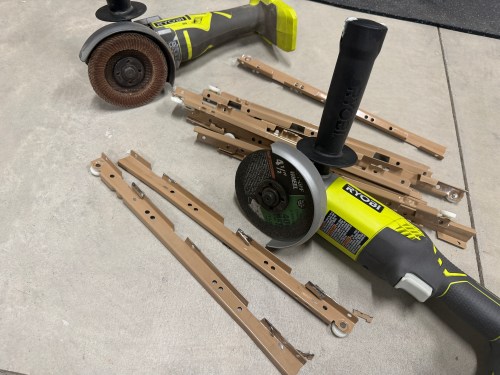
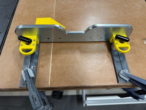
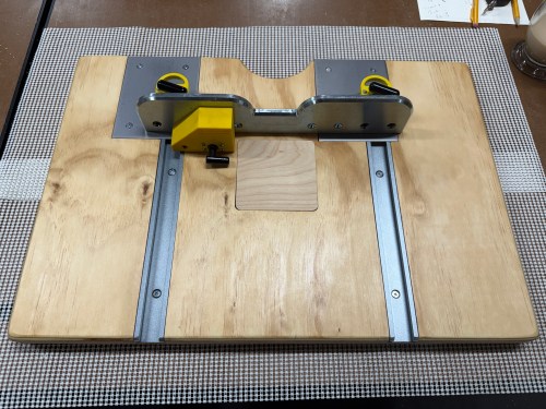
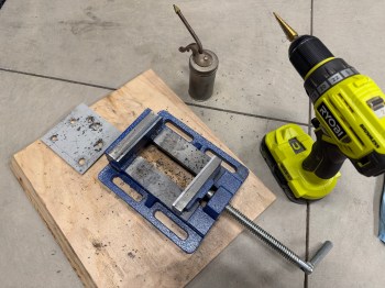
The wide slots are for T-tracks. One of my requirements for the table was to make it function with the Magswitch fence I had. So I bought 3/4 x 1/4″ steel bar stock, which fit perfectly through the top of the T-track. The shorts slots in the table offset to the left got additional pieces of metal, allowing me to move the fence over to clear the quill feed handles.

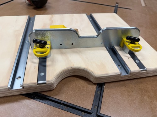
When I bought the flat bar, I place it across both magnets and I could not pull it off. That turned out to be a flawed test. After screwing in the short pieces as shown in that last picture I could easily move the fence. I did some research and found the 1/4″ thick metal was fine, but it needed more surface area to hit the magnetic field. I clamped two pieces of the metal side by side and couldn’t move the fence.

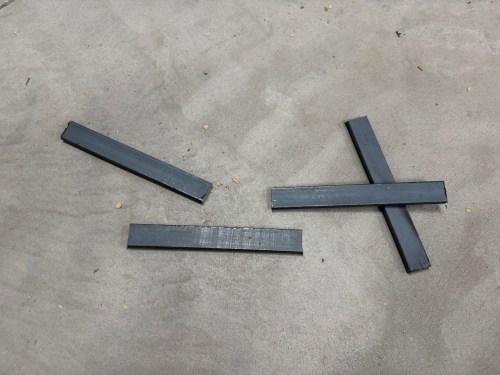
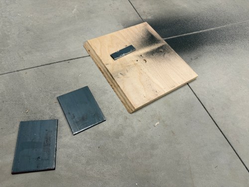
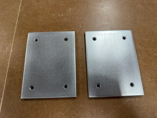
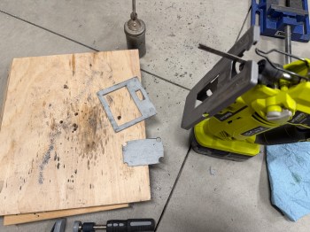
So I bought a piece of 1/4 x 4 x 12″ flat cold rolled steel and cut two 5-1/2″ pieces. Then I did a bunch of sanding and drilling before spraying three coats of lacquer.

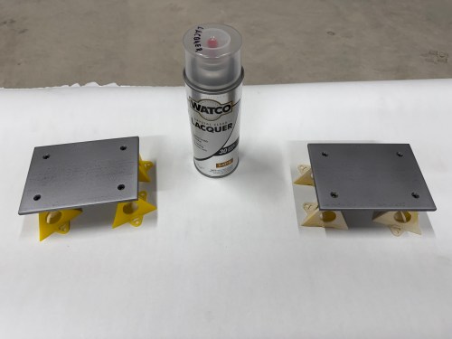
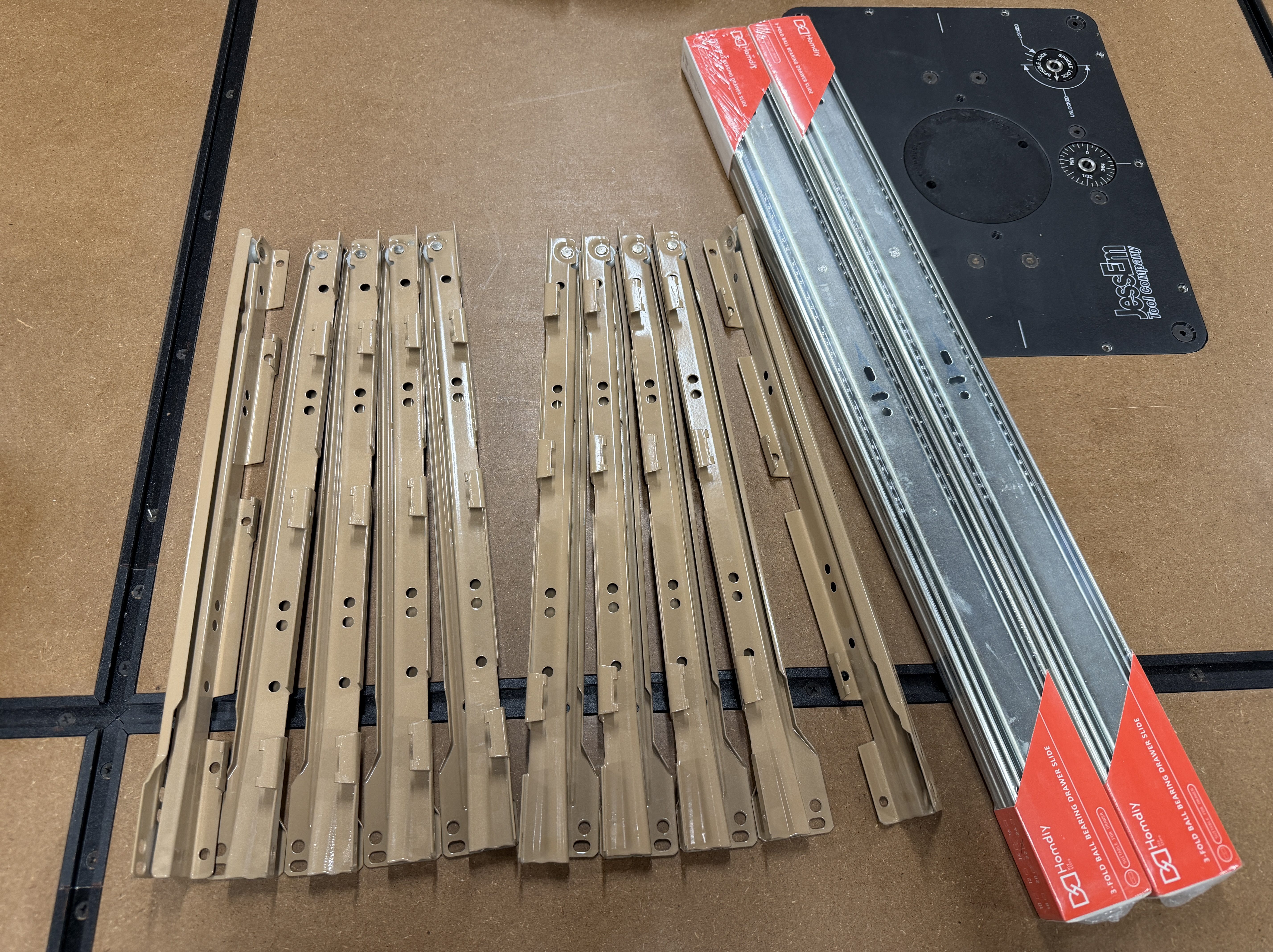
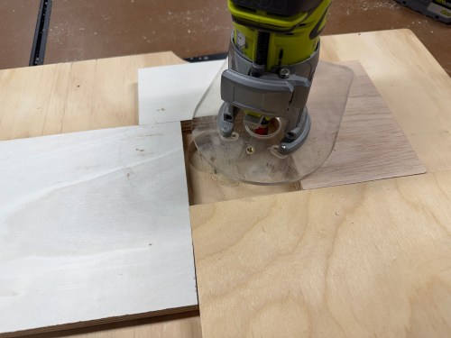
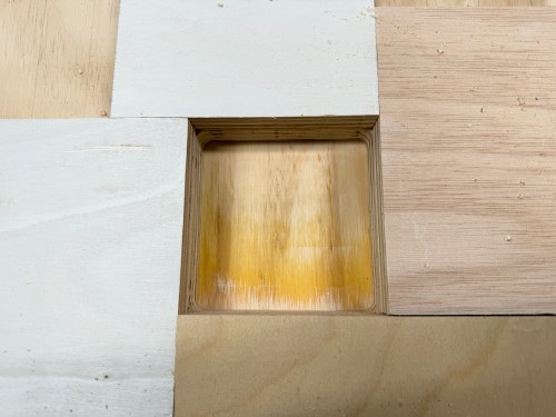
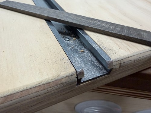
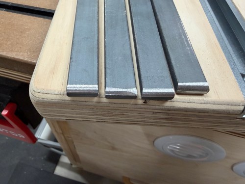
On the table, I cut and glued plywood in the back section of the T-track slots. After the glue dried, I routed large areas for the plates. I cut the T-tracks shorter, sanded the table, and gave it 3 coats of shellac. Then I mounted the tracks and metal plates. This turned out to be a much better solution.

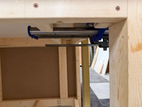
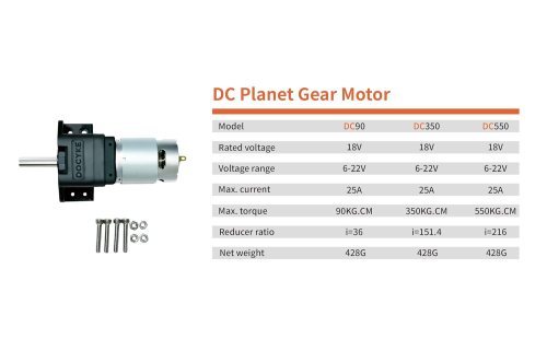
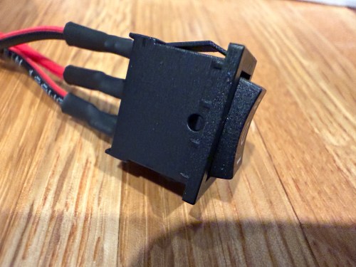
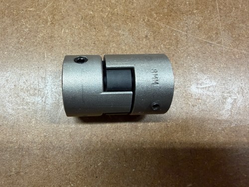
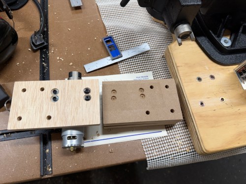
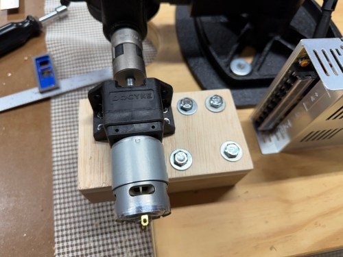
It was time to start working on a powerful upgrade. Raising and lowering a drill press table is usually a pain in the ass. This larger table actually got in the way of the hang crank and I wanted to motorize it. I bought a couple high torque gear motors, a momentary 3-way rocker switch, and a 15mm to 8mm flexible shaft coupling.

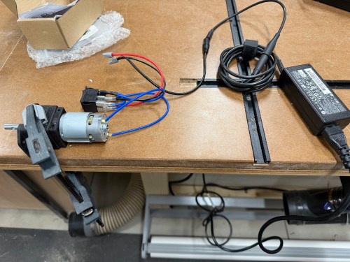
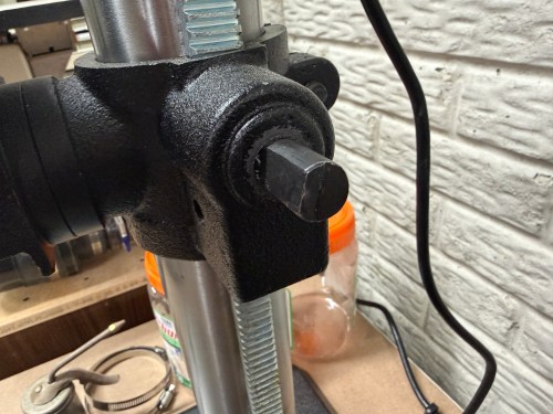
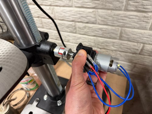
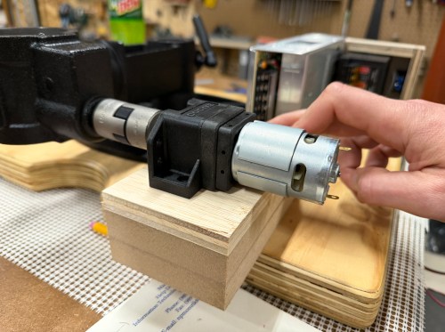
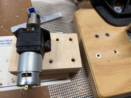
The crank shaft on the drill press is actually 9/16″, so the coupling was too large (I could only find metric sizes on Amazon). Three small pieces of aluminum can were thick enough to shim it and test. I connected an 18 volt laptop power brick, added extra weight to the table, and toggled the switch. It worked!

I had ordered both the DC90 and DC350 motors and went with the DC90. The beefier motor was too slow and has way more torque than I’ll even need.

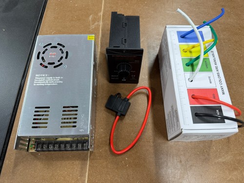
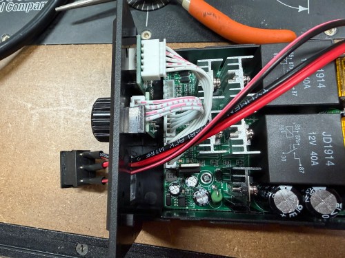
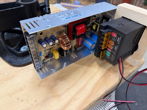
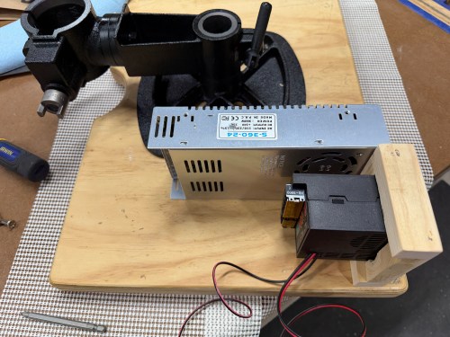
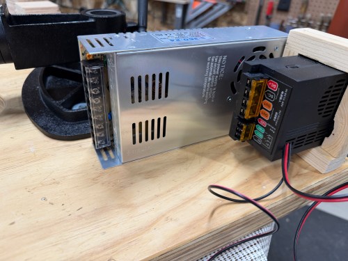
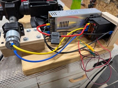
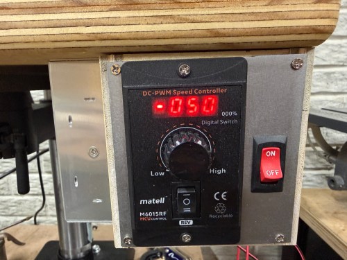
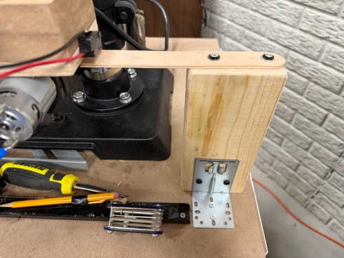
I bought a 24v power supply, motor speed controller, fuse, and 12 gauge wire. I also grabbed a toggle switch and limit switches from my parts bins. The toggle switch was so AC wouldn’t be constantly flowing to the power supply. The limit switches were to prevent the table from going out of bounds, which I do enough of on the golf course! I wired things up for an initial test.

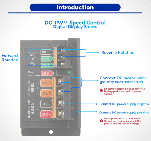
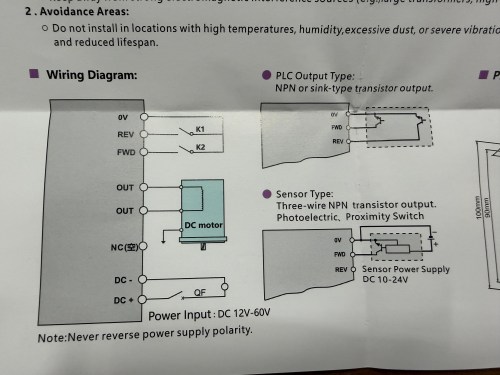
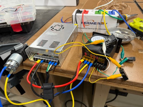
When I bought the speed controller there wasn’t much documentation and I was hoping the FWD/REV terminals would allow me to directly connect limit switches. They didn’t. At least not out of the box. The controller has two modes; you can use the switch on the front or bypass it with your own switch connected to those back terminals. In the picture above I got the bypass working with my limit switches and the 3-position switch used in my initial testing.

This was unnecessarily complex, disabled the switch on the front of the box, and meant I’d have to mount the additional switch. I opened up the controller to see how it worked. The case’s switch was plugged in to the circuit board, so I popped off the connector and connected it through my circuit instead. Bingo!

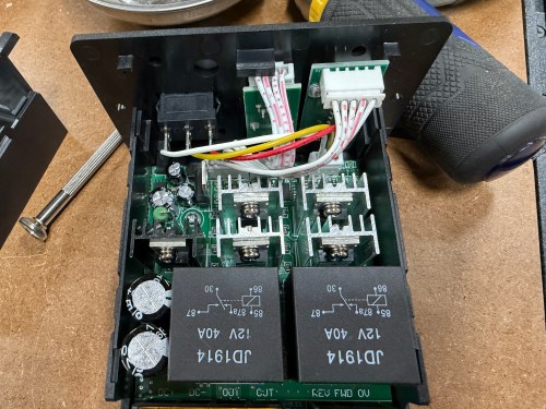
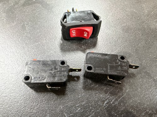
It was a latching switch, but I wanted a momentary 3-position switch, so I bought a pack. I soldered wires to the new switch, clipped a bit of plastic from the case, and fed the wires through the larger hole. The new switch was a perfect fit.

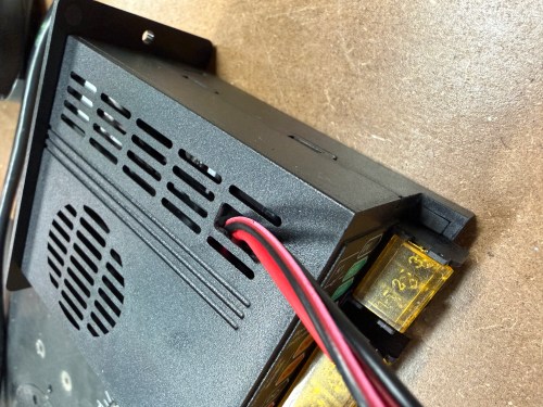
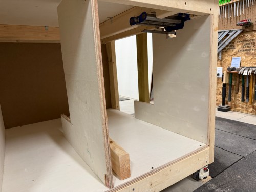
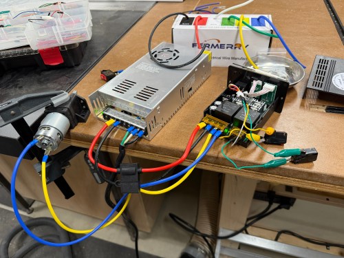
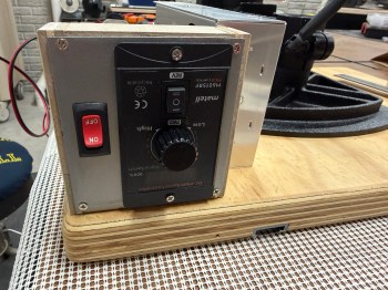
I took the original table off the drill press and brought it to my assembly table. First, I mounted the tables together and then screwed down the power supply. I made a custom bracket for the speed controller.

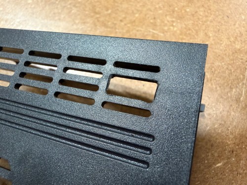
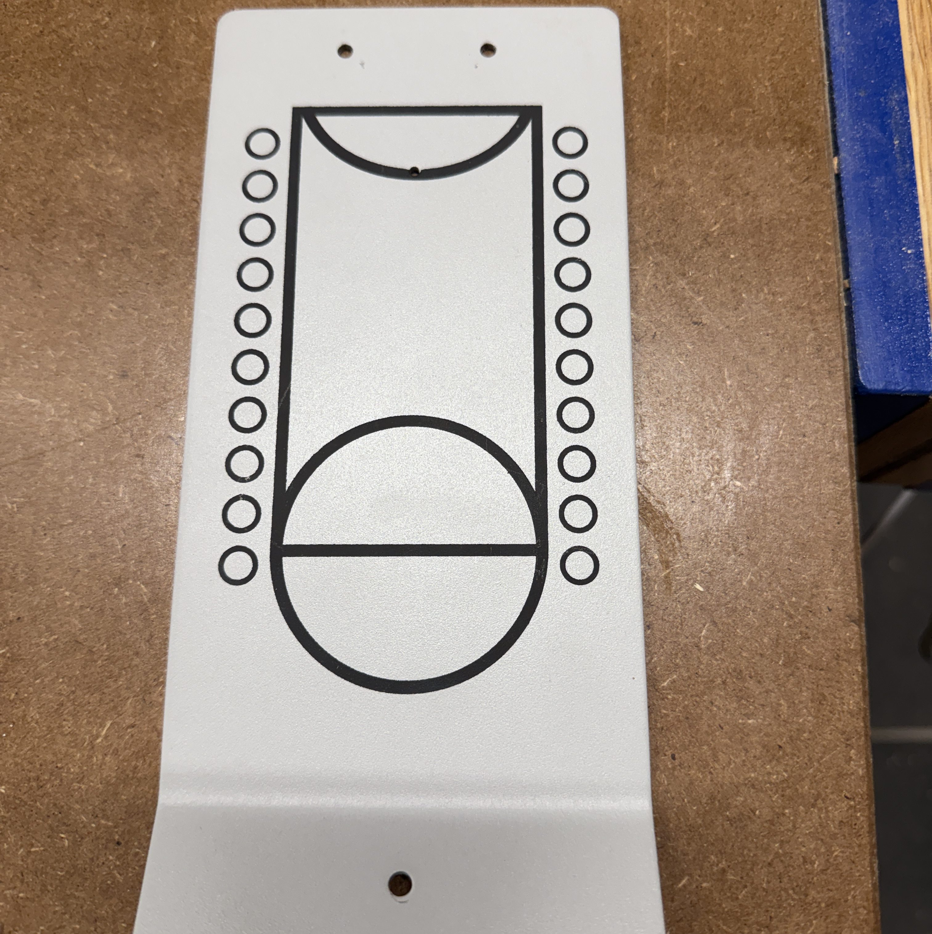
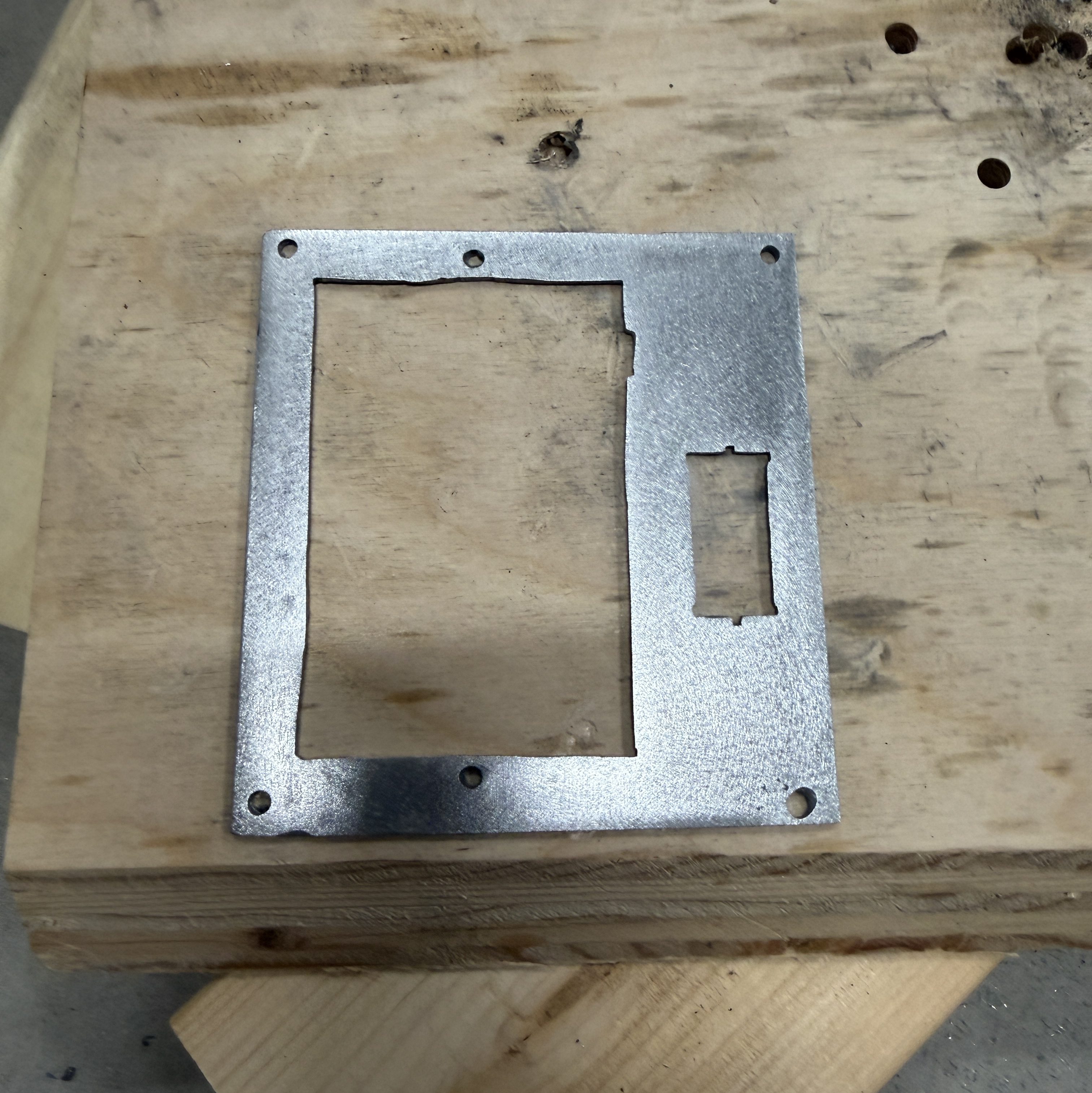
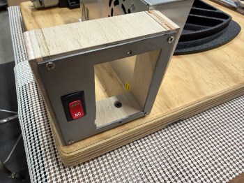
I forgot about the on/off switch though! So I scrapped the mounting bracket and made a new one. The second one used a piece of metal saved from a table top basketball game and turned out much better.

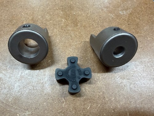
To make a proper coupling that would join the two shafts I ordered parts from Motion Industries:

The middle piece is flexible and would help with any misalignment, but I wanted to try to get the shafts lined up the best I could. I think it turned out pretty well.

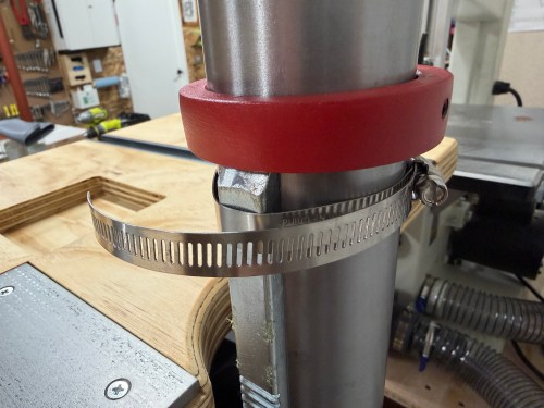
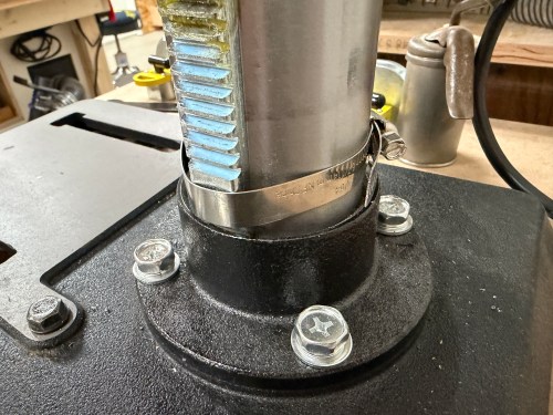
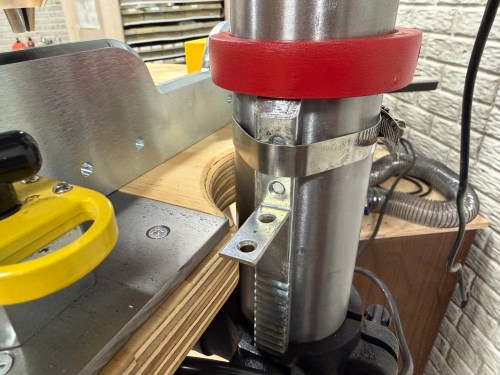
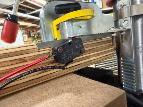
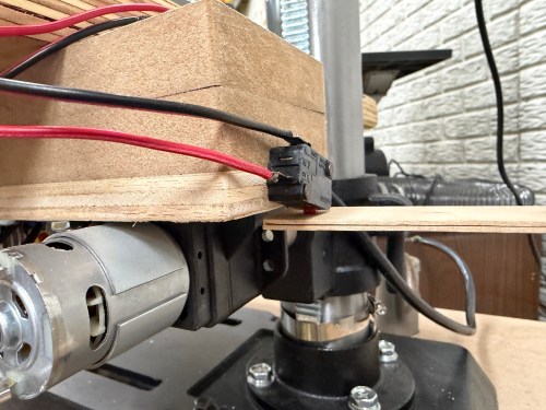
Then I put the table back on the drill press column. After squaring it to the cart, I tightened hose clamps around the rack to prevent rotation. I never need that functionality. Then I figured out the limit switch triggers and positions.

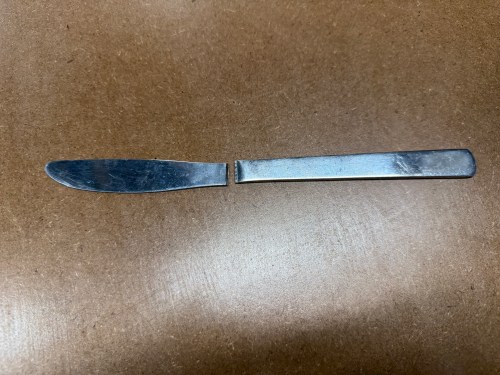
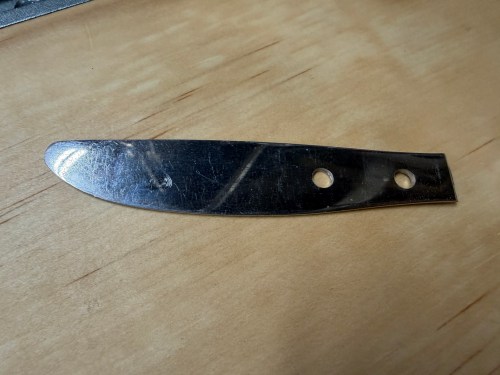
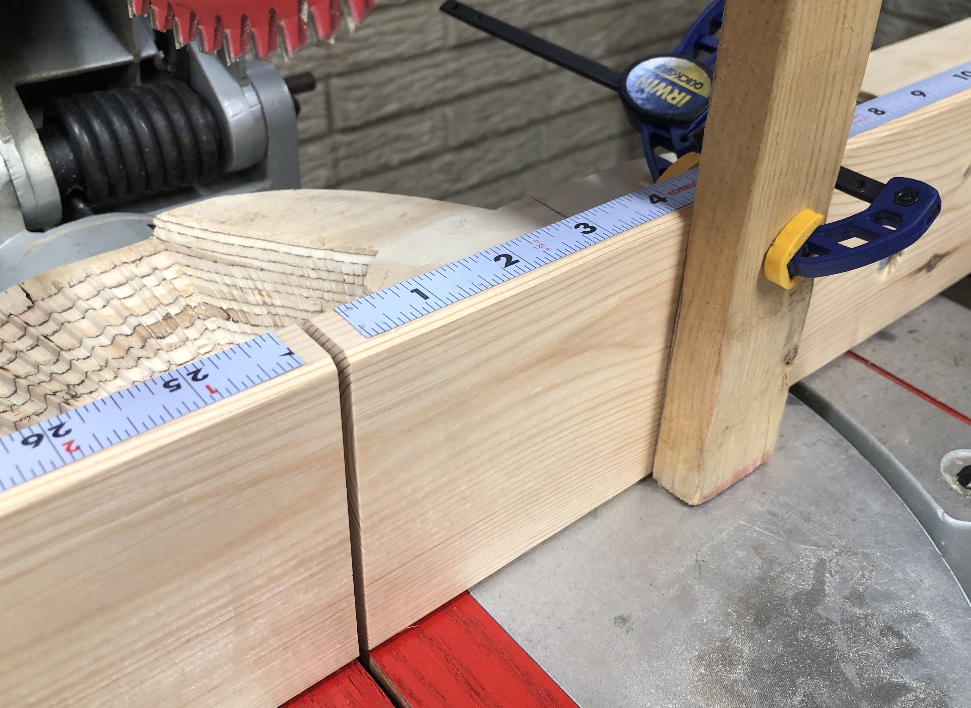
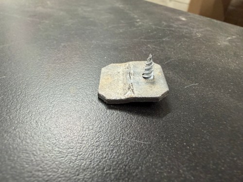
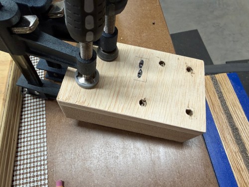
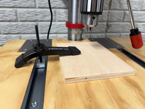
I hadn’t used the drill press much, but while drilling the holes in that piece of butter knife, I was already sick of the cluck key location. So I mounted the clip on the side of the table instead.

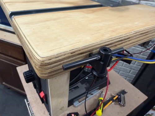
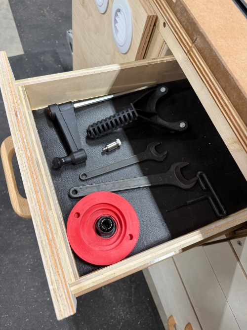
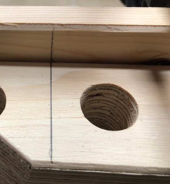
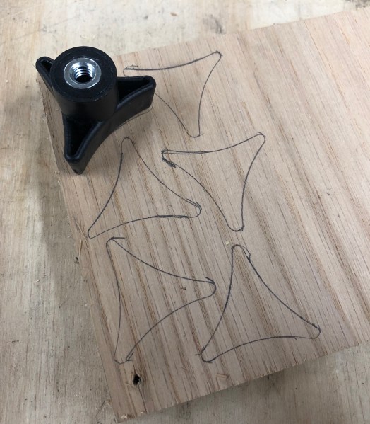
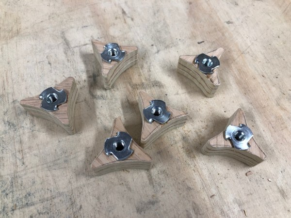
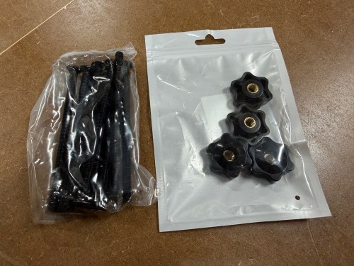
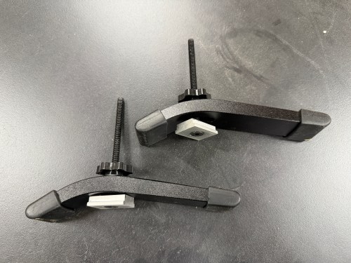
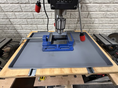
I had extra hold down clamps from the assembly table, so I bought M6 star knobs, 100m M6-1.0 bolts, and T-track slider nuts to make them useable for this table. I also bought a 19×12″ silicon tray for the table, to help contain the cutting fluid and chips, when drilling metal.

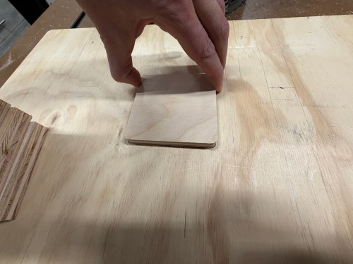
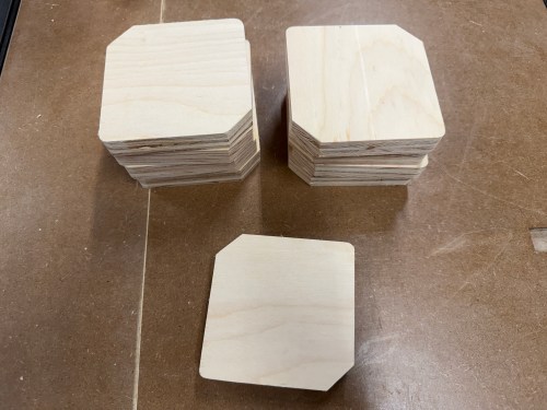
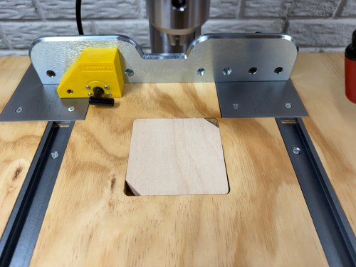
I forgot to cut corners off the inserts earlier, so quickly did that. It’ll make it much easier to get the inserts out of the table. Eight spares should last a long time.

Here’s a quick demo of the motor and limit switches. This thing is awesome!

This project was a lot of fun and is a big improvement to the machine.

Outfeed Assembly Table – Part 3

Time to finish this table. While part 1 and part 2 were quite involved, the rest was all about drawers. I needed to make use of the rest of the space inside the table.

First, I got to work on a cabinet next to the router station, on the front of the table. I wanted to use five sets of cheap drawer slides I salvaged from an old dresser. I had enough room for four deeper drawers, using 22″ slides. I took measurements and sketched out a plan. I had to design around the vice, which hung down below the frame of the table.

I cut a full bottom panel and some 2x4s for extra bracing. I wanted to make good use of space and have the most room for drawers on the right side of the table, so the vertical supports were made in the odd L shape again. The one on the left was cut to match up with the one from the router station.

In the middle, I needed something up top to connect to, so I cut a piece of 2×4 and would secure it in place after determining the exact width of the left drawer column. The vertical on the right needed some cut away around the vice.

Then I was able to cut all of the drawer sides, with two different depths for the different types of slides I was using. Or so I thought.

As I was going over some of my notes I realized I didn’t cut the back part of the middle and right verticals tall enough. To fix the mistake, I glued and pocket screwed on some patch pieces. I also had to recut longer sides for two drawers. From there I figured out the width of the left drawers based on the foam router bit storage tray I was using. Then I cut the fronts, backs, and bottoms for the five left drawers.

Assembly was quick with glue and brad nails.

I modified the old drawer slides with an angle grinder to remove tabs that were in the way for my use case.

I mounted the slides to the verticals for both columns of drawers. Then I was able to secure the left and right verticals to the table frame, attach slides to the left drawers, and put them in to guide the placement of the middle vertical. It got screwed in, along with the upper 2×4.

With the left column of drawers in, I figured out how wide the remaining parts needed to be for the right column of drawers and got them done. Then it was time for some drawer fronts and a false front, since the vice prevented a drawer from being installed there. This gave me a place for a recessed power strip with USB. I didn’t have enough matching handles, so I used two different styles I’ve bought at estate sales.

I filled in a few drawers.

I will never combine different drawer slides in a cabinet like this again. It was a major pain in the ass and too much to keep track of with the different mounting methods, widths, depths, and clearances. I had to adjust the placement of the old slides many times and alter some drawers. Wasn’t worth it.

The drawers for the right side of the table was much of the same and went together a lot faster. The table frame is slightly out of square, so the bottom drawer was a touch too tight and the top too loose. I had to route a recess on one and add some spacer material on the other. The handles were cut out of a test piece from the nightstands I made.

I cut a piece of shiplap paneling and closed off the back of the shelf. This leaves a little unused area in the middle back of the table. If I took out the drawers I could hide something back there. Shhh!

The saw outfeed and the huge work area are already amazing to have. This is really going to improve my processes in the shop. Here are some final photos.

Storage for a Ryobi Framing Nailer and Narrow Crown Stapler

Quick build this weekend to expand my Ryobi tool storage wall (which moved to the new workshop) with spots for the framing nailer I got last year to build the shop wall and a narrow crown stapler I recently bought on sale.

As I’m writing this and seeing the pictures, I butt jointed the back and bottom incorrectly, which is why it’s too tall and not deep enough to match up with the old spots. Oh well!

It’s great to be back in the shop again and getting it more organized.

Table Saw Cabinet

There was a big open space under the right wing of my new SawStop and it was the perfect spot for a cabinet to organize the table saw accessories.

I pulled out a sheet of plywood that got roughed up during the move. Went through a few iterations of how to size the cabinet and where to cut the pieces from.

Assembly went pretty quick, only using screws in case I ever want to make adjustments. It’s not going to hold much weight, so no need for glue.

I dug through my hardware to find hinges, handles, and a magnet catch. Since I should rarely move this thing, I attached a set of non-swivel castors, which only added 2″ of height.

When I went to slide it under the saw I had a moment of panic because it didn’t fit! I hadn’t accounted for the triangle-shaped brackets attaching the legs to the saw wing. I ended up removing the castors from the SawStop’s mobile base and the cabinet slid in. If I ever need to move the saw, it only takes a few minutes to put the wheels back on.

In the lower right, you can see the saw blade holder I recently made. I added old handles to make it easier to grab.

This cabinet was quick to make and makes great use of what would be dead space. Time to start building an outfeed table!

Nitrile Glove Dispenser

As I was finishing my closet reorganization I couldn’t help myself and had to make something. I have three sizes of nitrile gloves.

This gave me an idea based on plastic bag organizers I’ve seen on Facebook Marketplace.

I made a quick sketch, took some measurements, and grabbed plywood scraps.

It was a simple construction, using wood glue and pin nails to hold it together. I did screw on the back in case I ever need to get inside. I carved in the letters with whatever bit was on my rotary tool.

The top and bottom were made long so I could screw the unit in place.

I did finish organizing and cleaning the closet, so here are before and after pictures.

I’m glad that’s done. Time for some non-shop projects.

Improving a Delta Miter Saw: Part 3

If you haven’t seen the other posts, check out part 1 and 2 of this series about improving a Delta Sidekick 12″ Compound Miter Saw (Model 36-235).

With a fresh zero clearance insert plate, I wanted to move on to making a new fence for the saw. In the previous post I mentioned the cracked fence. It’s a significant one, so there was no fixing this.

miter-saw-crack

I forgot to take a decent picture of the fence before I took it off, but you can get the general idea from this old photo.

miter-saw-old-fence.png

After looking around, I found a YouTube video where someone had built a new fence and the shape of theirs was very similar to mine. It looked pretty straightforward and I had a few upgrade ideas of my own.

I jumped in by cutting four pieces of 3/4″ plywood to 4×36″ and glued them together. I clamped them to the edge of my work table, hoping it would flatten everything out.

On the table saw I squared up the edge that’ll be the face of the fence. Then I used the old fence as a guide to mark the mounting holes and some of the areas I need to trim. I’m going to have a secondary removable zero clearance fence, so I also marked the 4 original holes in the face plus two more since I’m building a longer fence (the 6″ left extension isn’t pictured below) that’ll overhang the edges of the saw’s table.

I moved over to the drill press and drilled all of the 1/4″ face holes. Then I used a 1″ Forstner bit with a depth stop to give the mounting bolt washers a place to rest. After that I was able to drill the rest of the way with a 21/64″ bit for the mounting bolts. I moved the bit over to a hand drill and made these holes oblong because they need adjustment room when aligning the fence.

img_1926

img_1927

Back at the table saw, I trimmed the sides. I also did most of the long cuts along the back. I switched to the band saw to finish cutting off the back pieces and then I did a little sanding with the oscillating single sander. While I still had the middle in tact, I figured it would be a good time to chamfer the edges, so I knocked that out on the router table.

img_1928

In the video that gave me this idea, he used a band saw to hog out the middle area. I thought I could use the miter saw itself to do this. It would give the area nice shapes, keep as much of the fence’s structure as possible, and hopefully provide a nice ramp for sawdust to be directed out the back. So I attached the fence, squared it up, and made the first cut.

I immediately noticed I would need to remove the fence if I ever wanted to swap insert plates. I went to make the first miter cut and it wouldn’t rotate. I thought I might run in to this. I removed the fence and used the band saw to make room for insert plate removal. I also sanded off the bottom of the fence where it was making contact with the rotating part of the table.

That was all good but now the back of the saw was hitting the fence at 11 degrees each way because I went with angles around the back instead of curves. I made adjustments at the band saw and then still had problems with mitered bevel cuts. Instead of taking everything off again, I used a hand saw, chisel, and files on the left side. After a ton of adjustments, I was able to make all of the miter, bevel, and combo cuts.

The final piece to this was creating the removable zero clearance fence. I started with an old piece of reclaimed wood.

img_1936

I used my jointer to flatten the face and square an edge. Then I ripped it to 3-3/4″ and trimmed the sides with the table saw. I used the bandsaw to resaw it and then the planer got the rest of the way to the 3/4″ thickness I wanted. To finish it off, I chamfered the edges on my router table.

img_1937

I clamped the board to the miter saw fence and drilled through the back of the original 1/4″ face holes to make marks in this board. I also drew lines on the left and right of both fences as a reference to make lining them up easier.

img_1938

I shifted gears to make some knobs. I grabbed one from router table, traced it, and cut six of out of 3/4″ plywood on the bandsaw. Then I cleaned them up on the sander.

img_1939

Over at the drill press I cut a 5/16″ hole through the center of each knob. I set a 1/4″ T-nut on top and hit it with a hammer so the prongs would leave marks where I could drill starter holes. Then I applied some cyanoacrylate and pounded each T-nut in.

img_1940

I grabbed the zero clearance fence and drilled the 1/4″ holes all the way through on the drill press. Then I set a 3/16″ (I think) depth stop, switched to a 5/8″ Forstner bit, and drilled the same holes. This would make a recess for the head of the carriage bolt.

I put the zero clearance fence in place up against the big fence, fed the carriage bolts through their holes, added a washer, and tightened the knobs. Here is what they look like from the back.

img_1943

Tightened hard this first time so the square part between the head of the bolt and the threads would pull into the wood and the head would set into the recess. Everything was straight and square, so I made the first cut. After the cut was established in the fence, I was able to attach adhesive backed ruler to the top, based on the kerf.

I didn’t plan it, but a bonus of the higher secondary fence is a perfect place for clamping a stop block when making repeated cuts.

This was a really fun project and is going to be so much better than the old fence.

One more thing to improve on this saw is the dust collection, but that project is probably on hold for at least a couple of weeks.