A big part of the planning for our house included Ethernet wiring because I want to hardwire every device I can, saving the Wi-Fi for devices that require it. It’s much easier and cheaper to get everything wired during the build, instead of adding later. I went through several iterations of the plan and in the end I had the electricians do 42 runs of Cat6:
- 4 jacks in the office
- 2 jacks in the office closet
- 2 jacks in the pocket office
- 2 jacks in the guest bedroom
- 4 jacks behind the TV
- 2 jacks in the living room
- 2 jacks in the dining room
- 2 jacks in the pantry
- 2 jacks in the laundry room
- 4 jacks in the walk in closet
- 6 jacks in the master bedroom
- 10 wires to 5 exterior camera locations (1 extra at each location)
They run it all up through the ceiling. I’m guessing that is to keep it away from most of the electrical. Here’s the master bedroom nightstand wiring as an example.
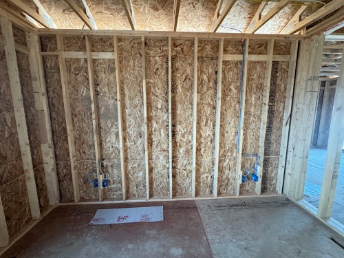
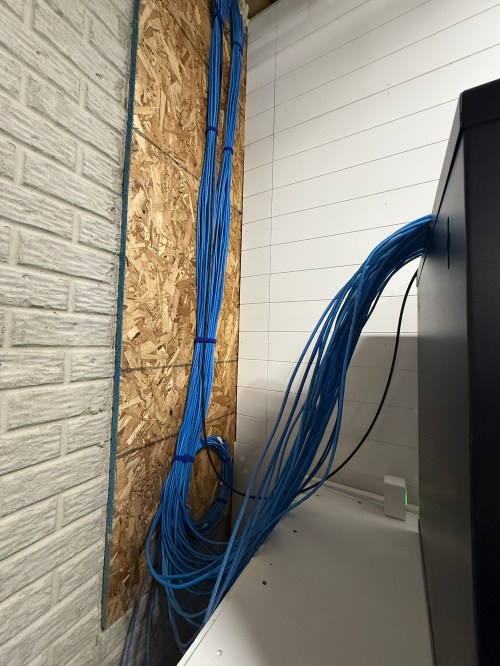
Then all of the cables comes over and down a wall between the laundry room and garage.

Ending at a single location in the basement.

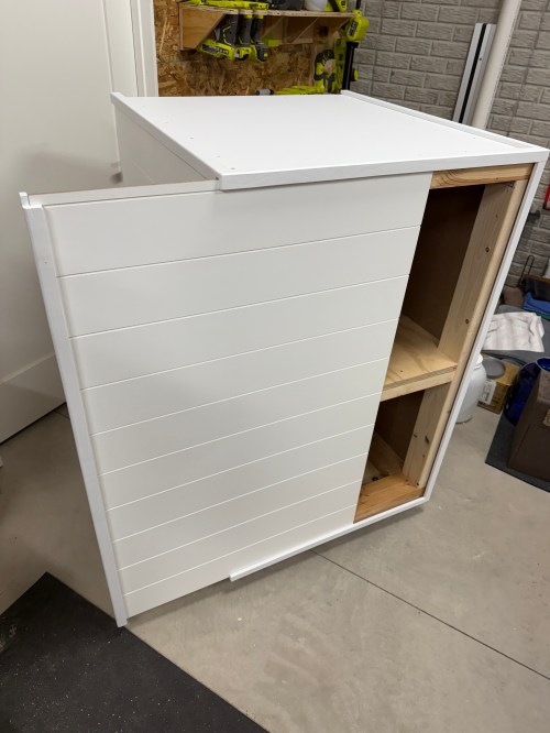
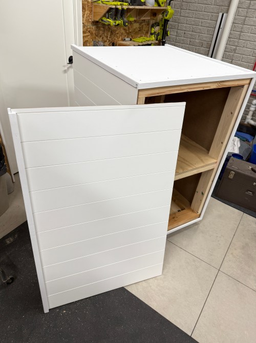
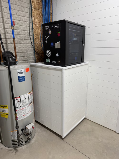
We built a wall (part 1 & 2) and since we moved in back in August I’d had the cable modem and old eero router sitting on top of the network rack filled with new equipment.

Last December I added some supports to the rack and couple of weeks ago I built a cart. Then I moved the modem and router inside.
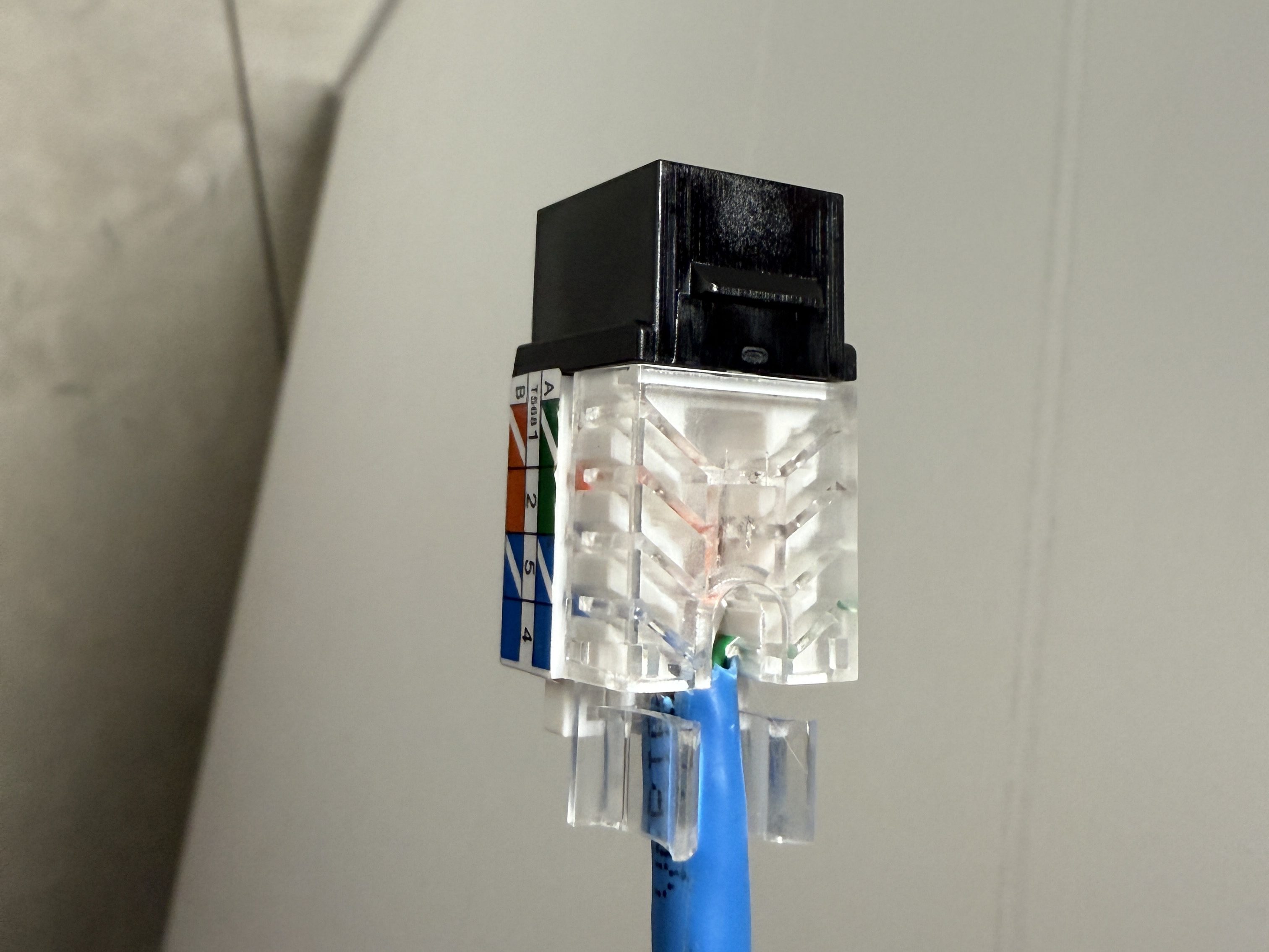
Throughout the house, I put port covers on the unused jacks. Here’s how a wall plate looks with one port open and one covered. The covers will help protect the internals and keep dust out.

What did I buy for my network? A LOT! Here’s all of the stuff for the rack, cables, and tools.
- NavePoint 19″ 12U rack with glass door, cooling fan, removeable side panels, and locks
- 2x Everest 24 port keystone patch panel
- 50 black and 10 white Everest 45° angled Cat6 keystone jacks
- 500′ Southwire 23AWG Cat6 UTP cable
- 5x Cable Matters 10′ Cat6 cables
- 10x Amazon Basics 3′ Cat6 cables
- 16x GearIT 1′ Cat6 patch cables
- 20x GearIT 0.5′ Cat6 patch cables
- 100x CableCreation Cat6 RJ45 connectors
- 2x Pyle 1U server rack shelf
- Jingchengmei cable management panel with brush
- 20x white, 20x black, and 20x orange RJ45 port covers
- 20x VCE blank keystone jack inserts
- 50x M6 x 16mm rack mount cage nuts, screws, and washers
- 2x male C14 to 90° down right angled female C13 power adapter
- Tripp Lite SMART1500LCD 1500VA rack mount UPS
- Everest 45Term – 45° angled speed termination keystone tool
- TRENDnet Crimping Tool
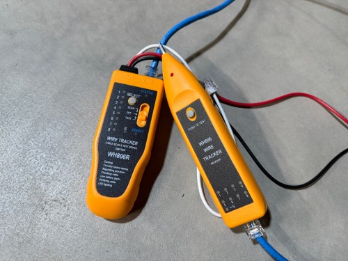
- iMBAPrice IMBA-WH806R wire tracker & tester
- iMBAPrice 4-in-1 remote network cable tester
- Wire comb
- 32′ Double-sided hook-and-loop cable management tape

When it came to the actual networking equipment I took a good look at the stuff from Ubiquiti/UniFi. It’s top of the line, which is reflected by the price tag. I decided to go with TP-Link instead, saving a lot of money.
- TP-Link ER605 router
- TP-Link Omada OC200 hardware controller
- TP-Link TL-SG3428MP 24 port managed PoE switch
- 2x TP-Link EAP610 ultra-slim wireless access point
- 2x TP-Link EAP615-Wall access point
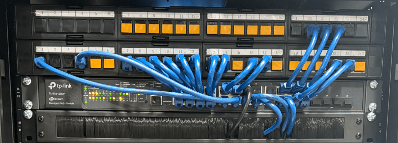
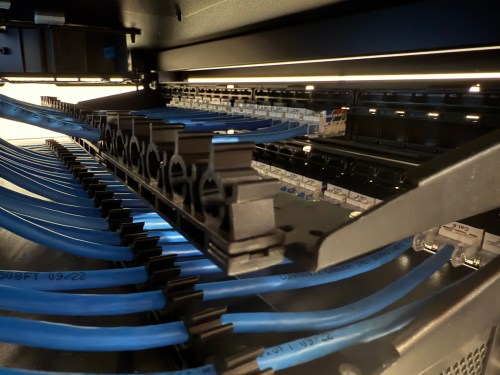
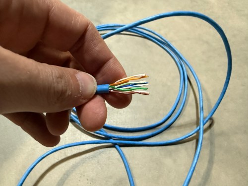
Before I started wiring everything through the rack, I cleaned up the cables.

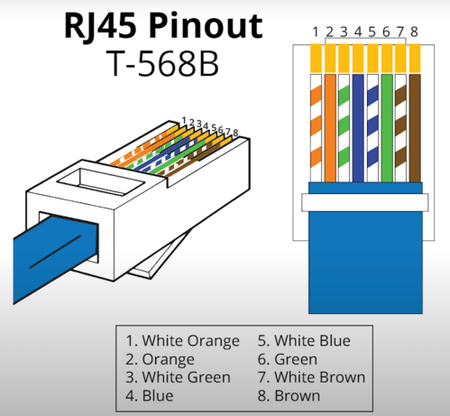
The electricians had done all of the wall jacks throughout the house with the newer T-568B wiring standard, so I followed suit. I learned how to wire the keystone jacks and insert them in to the patch panels.


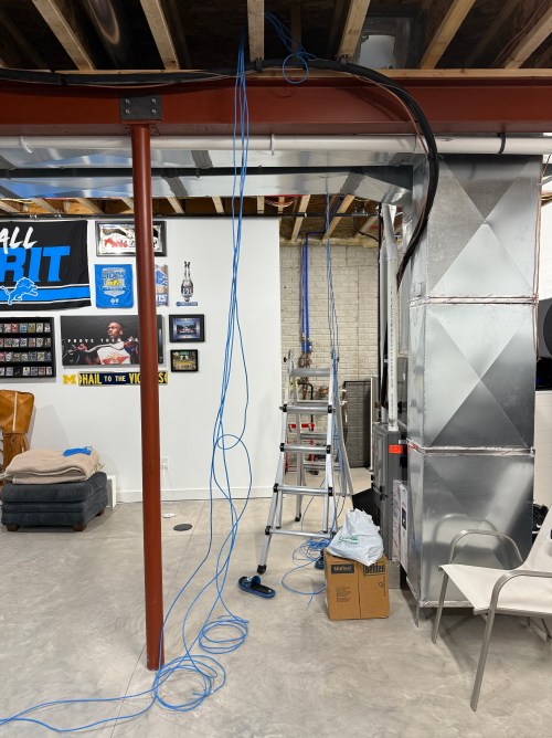
I’d never done anything like this and it was so much fun. By the end, I was pretty quick with each keystone jack. I highly recommend the Everest 45° ones and the tool for it. The basement needed some Ethernet ports for the golf sim, so I ran four new cables from the rack. I installed a couple of electrical boxes in the ceiling and wired jacks there.

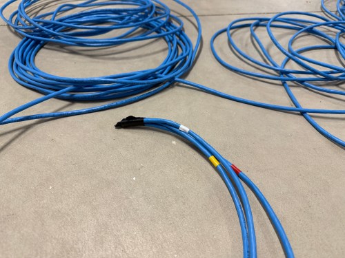

I also needed a custom length Ethernet cable to run from the ceiling jack down to the gaming PC. I’d tried putting RJ45 jacks on the end of an Ethernet cable or two a long time ago and remember it being almost impossible. After watching a quick YouTube video (even though I don’t have pass through connectors), I was able to put both ends on my new cable without a problem and it passed the test.
Then I was able to use patch cables to connect ports on the patch panel to the switch as well as hook up the cable modem, Pi-hole Raspberry Pi, and TP-Link equipment. There’s also a Dell Micro in there, which I’ll cover in a later post about smart home.

When I tried to access the Omada controller I couldn’t bring up the web interface with Chrome on my Mac. After trying a bunch of stuff I checked from my iPhone and it worked. I tried Safari on my Mac which also worked. It turned out I had always prevented Chrome from accessing my local network. I flipped the switch in System Settings and the interface loaded.

At another point I accidentally disabled all of the ports on the switch. The UI splits the switch ports across three pages, and on page two I had clicked the button to select all, unselected a port, and disabled the nine other ports. I quickly realized it disabled 27 of the 28 ports. I was so pissed! Every other UI I’ve ever used will only select the items in view when you click the Select All button, but not the Omada Controller software. In order to get back in I had to access the switch via the USB console, reset the switch to factory settings, and start over.
I’m running four VLANs, named Default, Guest, IoT, and nIoT. IoT is for my Internet of Things (smart home) devices that need to access the Internet and the “n” in nIoT stands for “not” since I don’t want them to access the Internet. The Default and IoT networks are set to get their DNS from my Pi-hole server, which blocks ads and other malicious domains.
Each VLAN has a matching wireless network. The Guest Wi-Fi is set as a guest network, which automatically prevents any device from accessing another. The wireless networks for IoT and nIoT are only set to use the 2.4 GHz band since most of the devices will not work on 5 GHz.
I added mDNS rules for Printers and AirPlay devices from the IoT network to the Default network.

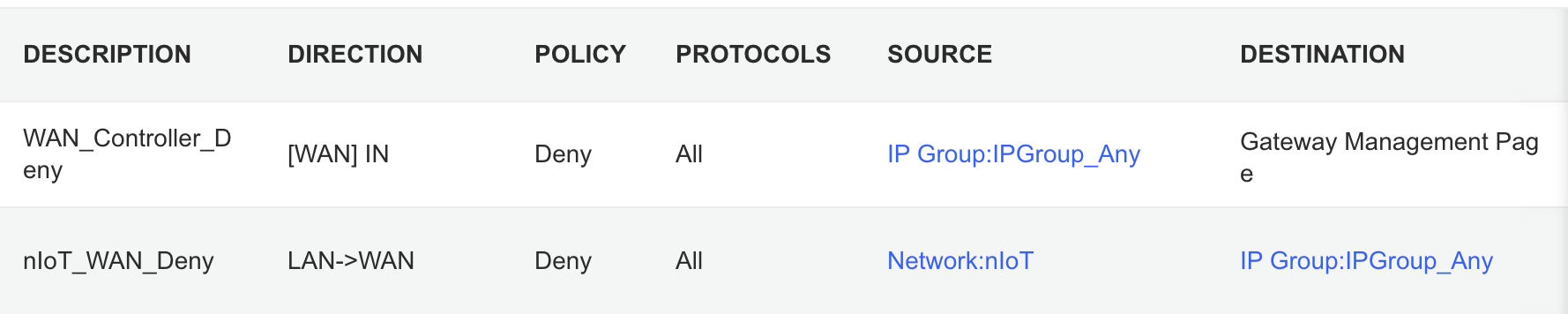
It took me awhile to figure out the ACL rules. I have two for the Gateway. The first prevents any outside IP from accessing my network management page and the second prevents the nIoT network from accessing the Internet.
I ended up with six rules for the switch, since the default behavior of the Omada stuff is to permit everything. With my Pi-hole server on the IoT network I had to allow it’s IP to access anything on the Default network (this should probably be limited to specific ports). I had to allow some ports from the camera IPs to access the Default network and I had to allow some ports from my Home Assistant server to access the Default network. I may find out I need to adjust those ACLs, but more on those smart home aspects in a future post. Then the IoT and nIoT networks are denied from accessing Default and a bi-directional rule prevents the Guest network from accessing any other network.

Seems to be running pretty well. I have some smart home stuff on the network, but haven’t connected any of the light switches yet and have a lot of Home Assistant configuration to do. Originally I didn’t have an access point in the basement, but after a few days realized it was necessary and added one. Here’s a view of the network topology, automatically generated by the Omada controller.

If you upload a floor plan and place walls, the software can even run a wireless coverage simulation. The house has great signal and the yard should get good connections as well.

Power over Ethernet is pretty sweet. It’s so nice not needing power cables for the 10 devices with PoE support.

Time to finish setting up my server and smart home devices. Watch for an upcoming post with all of the details.