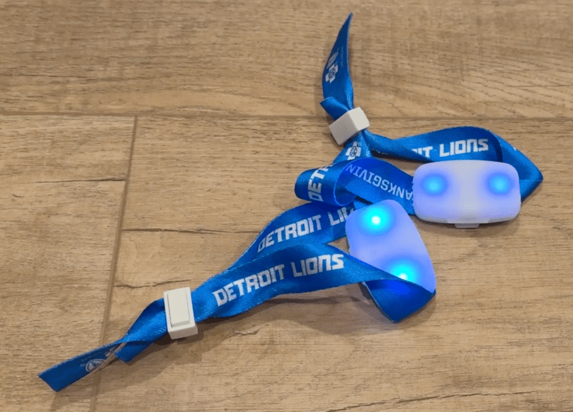
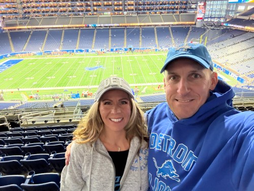
When we attended the Lions Thanksgiving game in 2024, we got these wristbands.
You’ve probably wore one at a game or concert or at least seen them on TV. When everyone at a venue wears one, they create cool lighting effects. They were still flashing when we got home that night and I took a video.
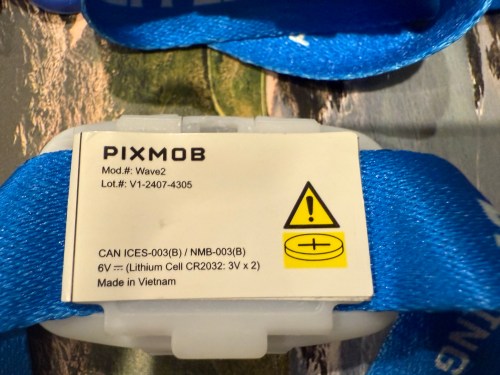
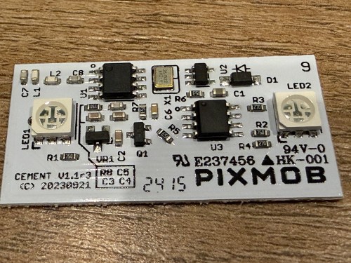
I’ve always wondered how they work. A few weeks ago I found them in a box and dove in. They’re made by a Canadian company called PixMob.
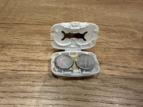
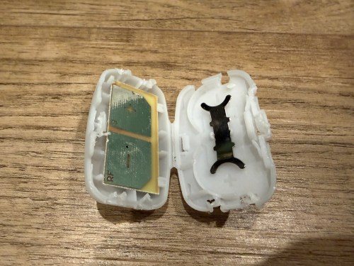
Inside the plastic case is a small circuit board powered by a couple of CR2032 coin cell batteries.
Some models work via Infrared (IR) and others by Radio Frequency (RF). Almost every remote control you’ve ever had uses either IR or RF. This board actually says RF on one of the battery contact points. After putting in new batteries I found RF captures on GitHub and used my Flipper Zero to broadcast the RF signals.
Pretty neat. I doubt I’ll ever do anything with them, but now I know how they work.’
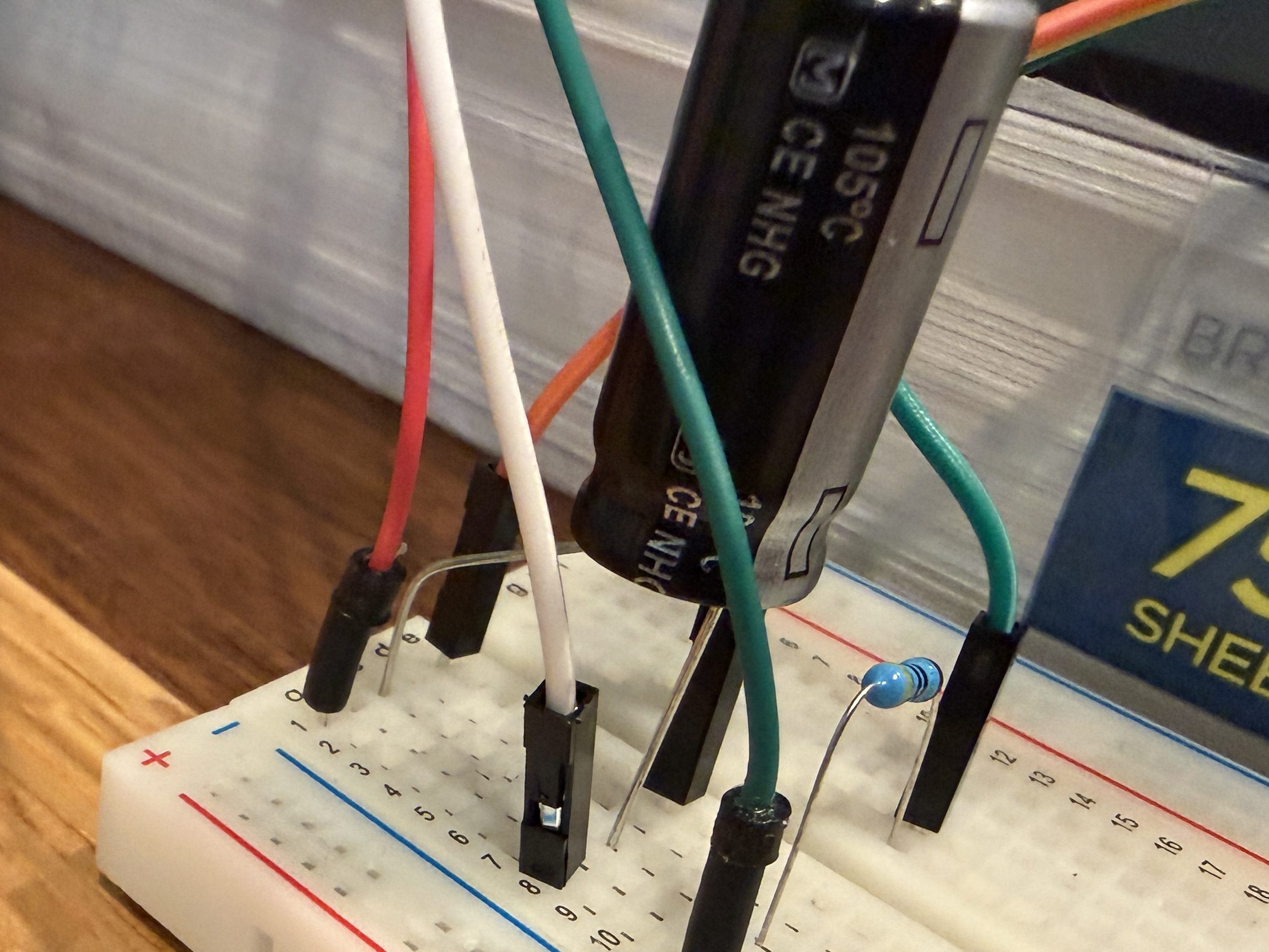
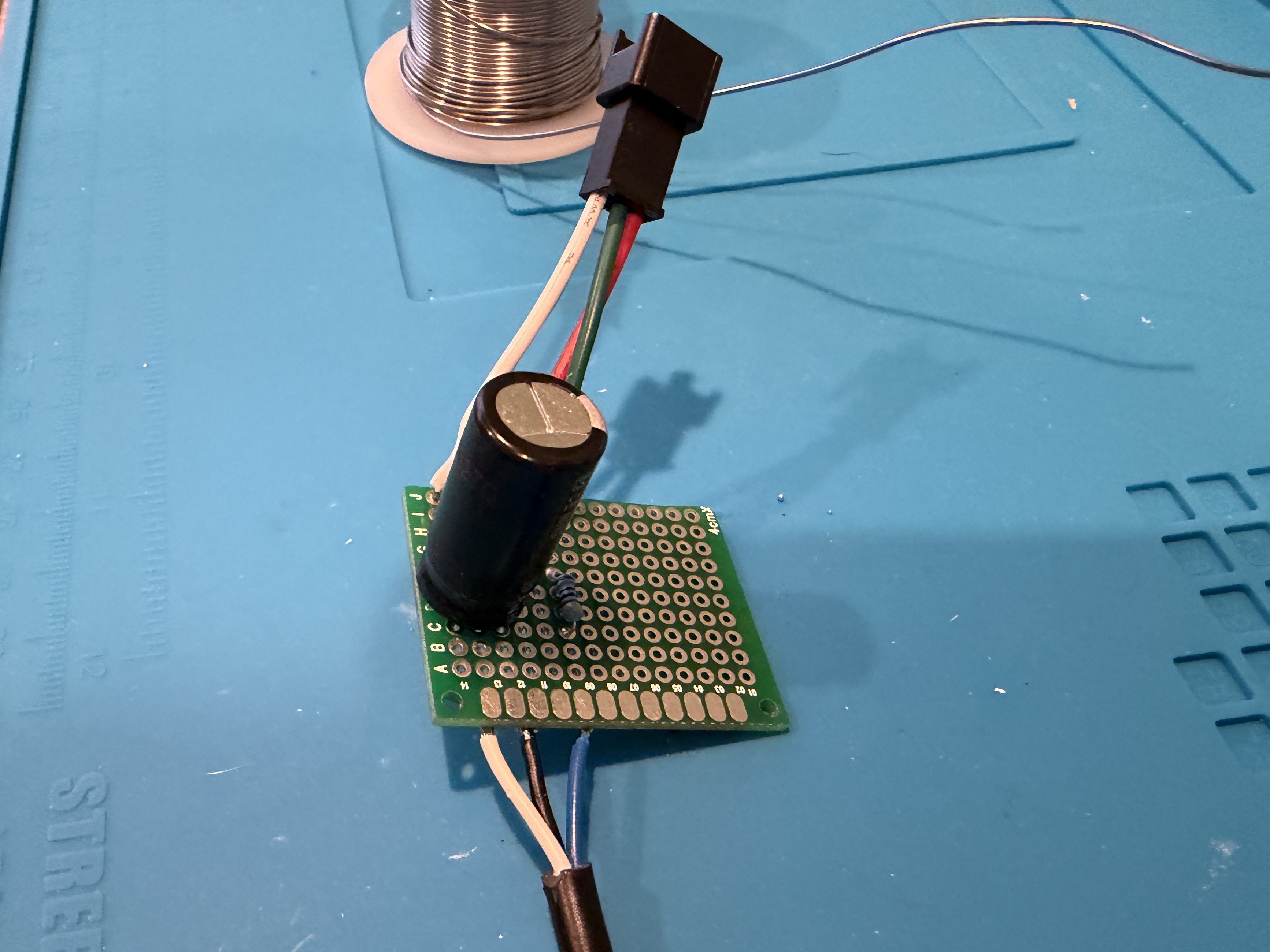
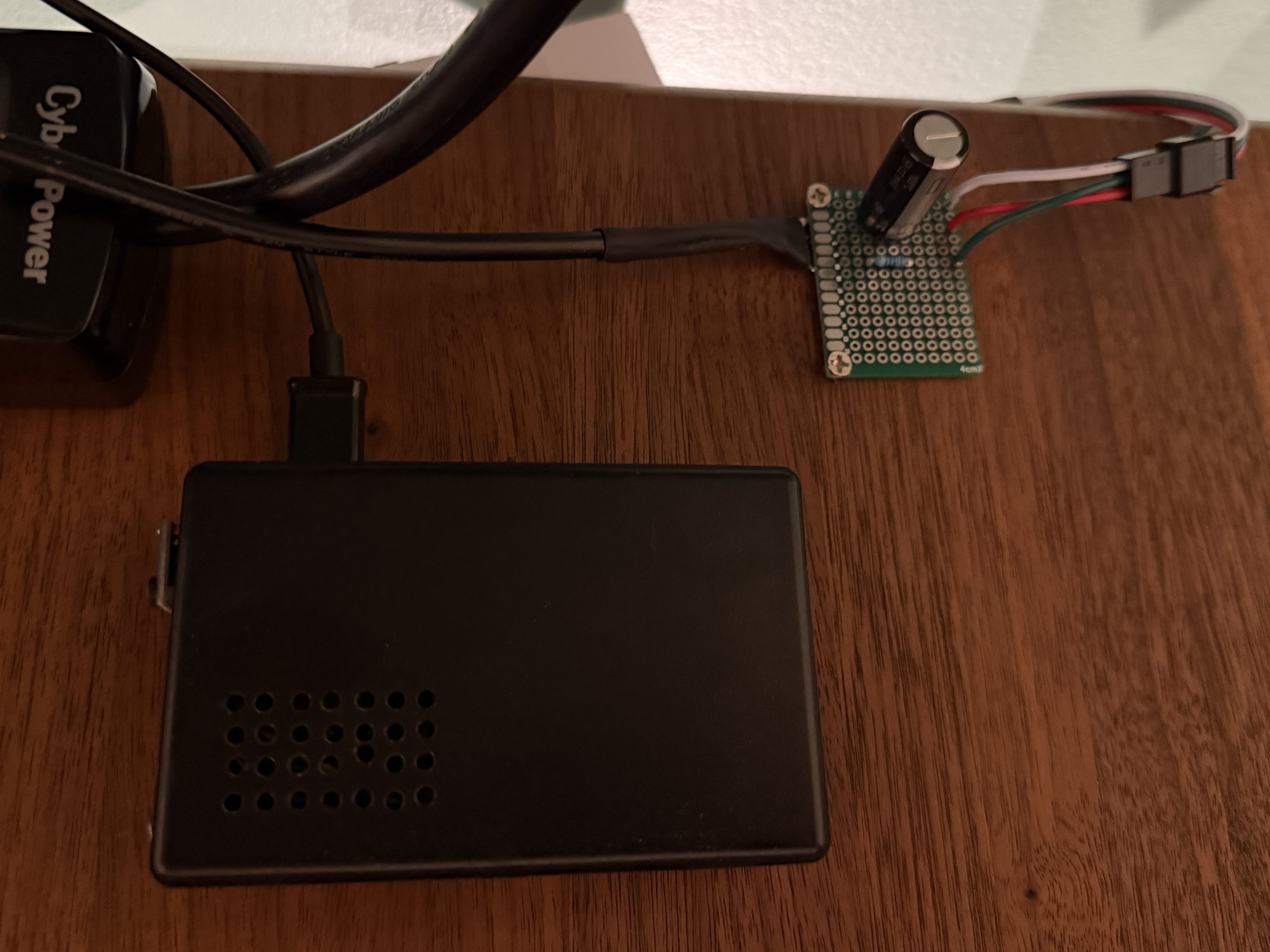
I picked up a 5m strip of adressable LEDs for my PyPortal device. The strip has 60 LEDs/m, which is double the density of the Neopixel strip I fried. To prevent future accidents, I tested improvements. Adding a 1,000 µF electrolytic capacitor protects the LEDs from a power spike and a 470Ω resister protects the first LED from data ringing.
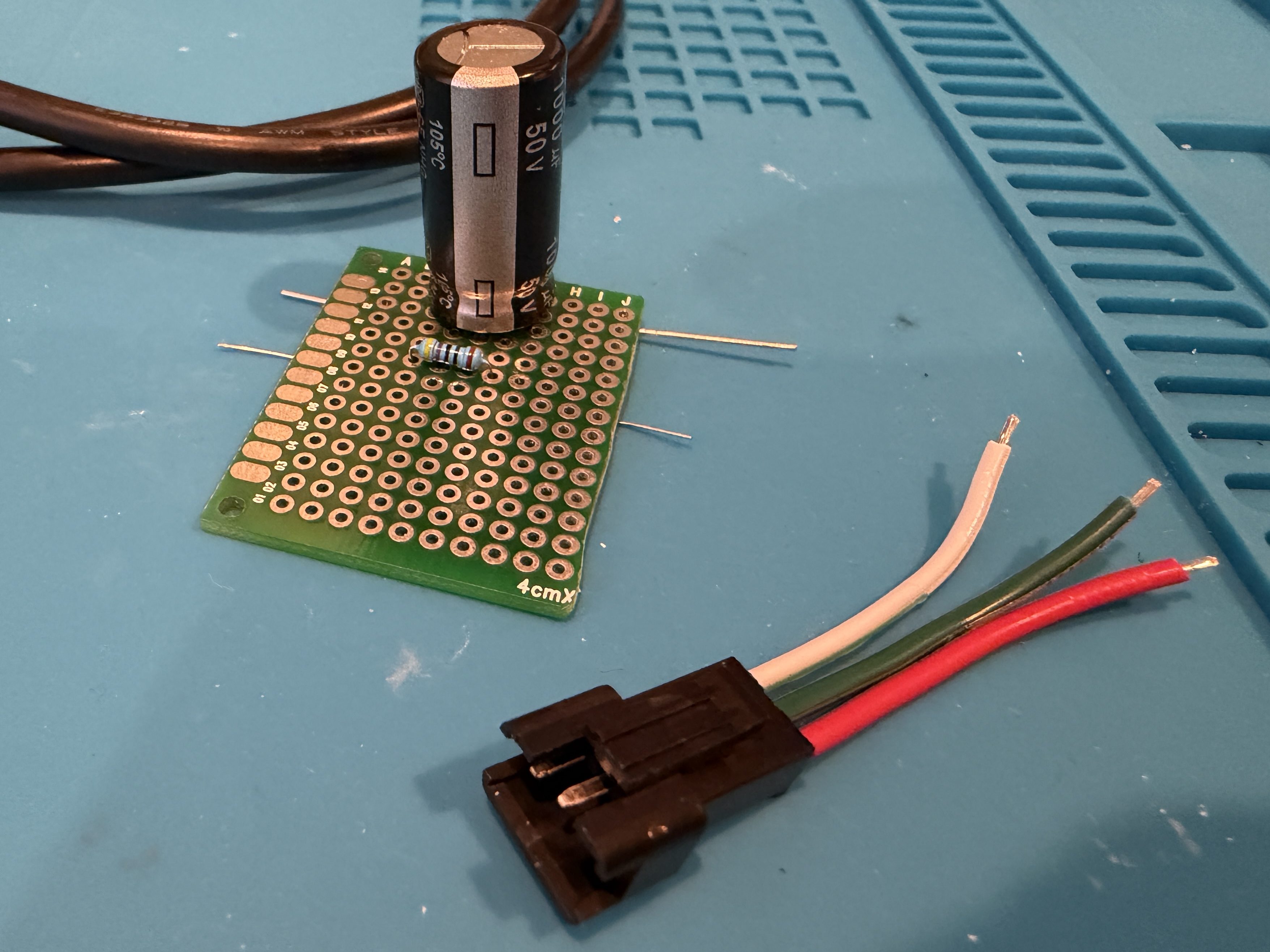
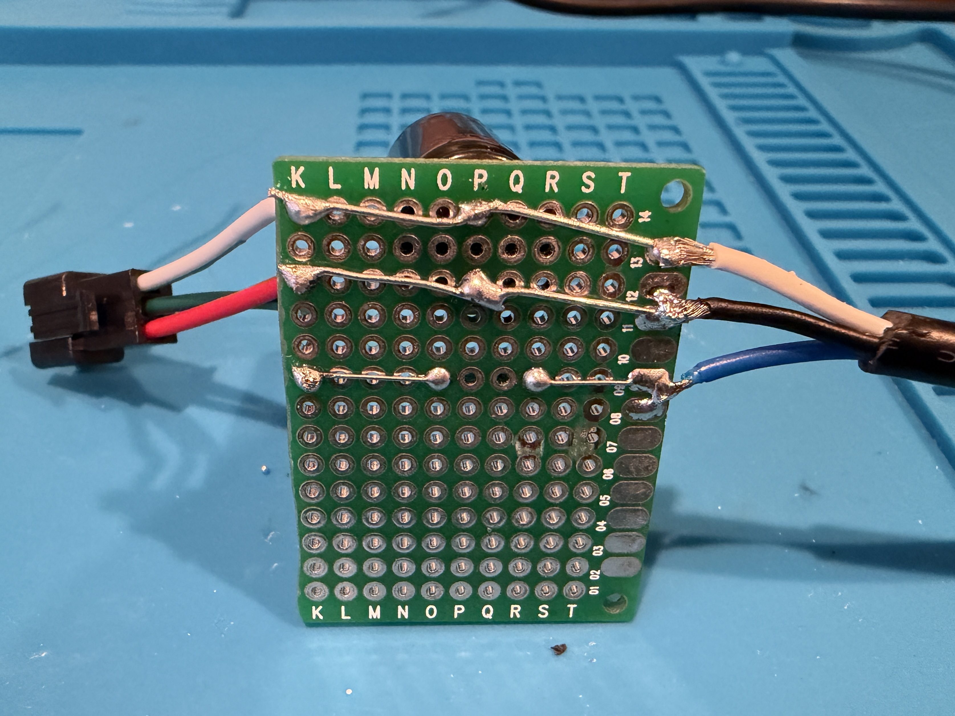
Everything worked great, so I cut off a section of 62 LEDs. Then I worked on a little board and better wiring.
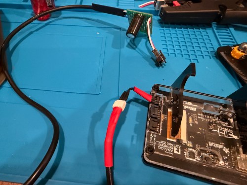
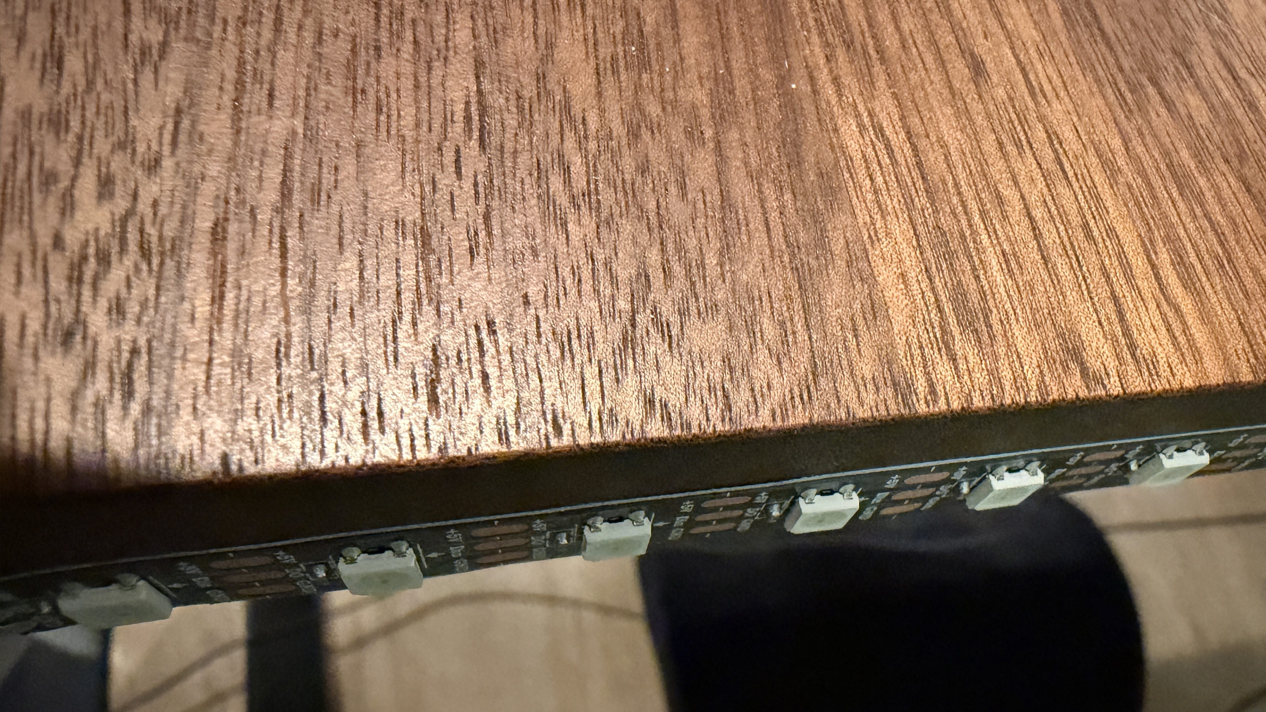
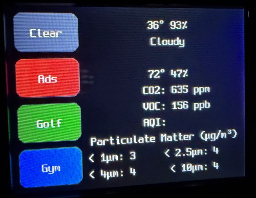
I didn’t trim the protoboard, so I could use the two holes to screw it to the undersize of my desk. This LED strip had an adhesive backing, which worked much better than the clips. I did a bit of cable management and also mounted the air quality monitor under the desk.
The code, which can be found on GitHub, got a bunch of small improvements:
Updated the LED count
Limited brightness to 50%, which is plenty and helps with power draw
Adjusted the pulse functionality to account for the brightness limit
Added a button to the interface which can be used to clear the LEDs
When filling a color, reset the LED params global, so an animation won’t play on the next loop
Tweaked the chase functionality to work better with the new LED density
Changed the button success animation so the loop continues sooner
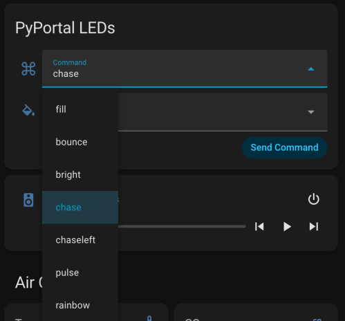
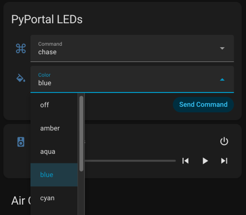
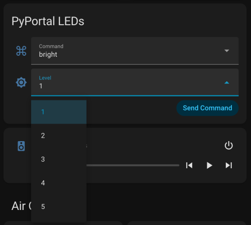
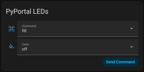
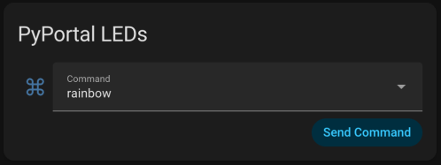
I had Google Gemini help me some stuff. First was to update the PyPortal firmware and CircuitPython version. Then update the code to make it compatible with CircuitPython 10.03. I also made an interface for my dashboard where I can select the different commands and options to send to the device manually instead of typing them in through Developer Tools -> Actions in Home Assistant.
Here’s a new demo video, so you can see how it works and what the lighting looks like.
Of course, the real power still comes from automations, where something happening around the house triggers Home Assistant to send commands to the device. Time to work on more of those. Almost a year later and this project is finally where I hoped it would end up.
Pease-out was project #32 of the Boldport Club. This kit is kind of boring one, since it’s main purpose is a tribute to Bob Pease, an expert analogue designer. Adjustments to the potentiometer change the output frequency of the LM331, which can be observed by the flashing LED.
It was a simple build and removes another project from my todo list.
A couple of weeks ago I assembled one of the BoldPort Club kits I had piled on my desk. This one was project #8, titled LIGEMDIO. It’s an LED tester and the name comes from the first letters of Light Emitting Diode, LED.
It was a cool little build after I swapped out to an old soldering iron and it’s a project I’ll actually get some use out of. Would have been nice to have when I tested all of the LEDs for the 8x8x8 cube.
Back in January, I finished assembly on the 8x8x8 LED Cube. Around the same time I bought an acrylic case for $13 from AliExpress. The case isn’t designed for this specific cube, but this style of case is the only option available anywhere.
Needless to say, it needed some modifications. I had to drill new holes in the bottom to match up with the mounting holes of this particular board. I also opened up some holes in the back for easier access to the power switch and programming pins and in the side for the power plug.
After the mods, everything went together surprisingly well.
With all of the soldering and LEDs, the cube is very fragile, so this case should keep it safe. Over 14 months after receiving HackerBox #0030: Lightforms, the full assembly is finally complete. Now I have to update the firmware so I can program my own animations.
My last HackerBox, #0030: Lightforms, came with an 8x8x8 LED cube kit. I started building it in May, when I assembled the PCB and made a jig for assembling the grids.
I got busy over the summer and the thought of soldering 512 LEDs didn’t excite me. After catching up on all of my other kits, it was finally time to dive back in.
I thought I took some video of assembling the board, but I must have deleted it. So I didn’t bother with any video while assembling the grids either. The repetition would have been quite boring. I thought I’d do a gallery with captions for a change.
Assembled circuit board.
Simple circuit used to test the LEDs and compare brightness.
3D printed jigs. I ended up not using the grid one because my plywood jig fit much better.
My friend Kevin printed this awesome jig, which made bending the legs much easier.
Over 500 LEDs before and after being bent. It took over 90 minutes to test and bend them all.
One 8×8 grid all soldered in the jig.
All 8 grids completed without burning a single LED. I can’t believe I didn’t swap the leads when I bent them all.
Complete! Only had to rewire the cathode connections to the board because the instructions were actually wrong.
While assembling the 8×8 grids I settled on a pretty good system, so I recorded myself doing a couple of rows to show my method.
This is definitely my longest electronics kit in terms of hours spent and it had so much repetition. Pretty cool result. Here is someone’s demo showing what can be done with the cube.
I’ll need to upgrade the firmware so I can program the board with my own animations.
I wired a 9V in series with two AA batteries (1.5V each) to test out the truck‘s dash panel bulbs.
Turns out the bulb holder I tested first was faulty and 9V would have been enough. In fact, three of the nine bulb holders were corroded and unable to provide juice to the light bulbs. That explains why it was so hard to see the gauges at night!
To get by until new parts arrive, I was able to finesse some small pieces of wire in between the bulbs and the holders to get an electrical connection.
It’s disappointing that HackerBoxes resold us a popular kit that you can get for $15-20. I’ve seen these LED cubes many times online and while they do look awesome, I never bought one because I didn’t think I’d have the patience to put one together. I guess I’ll get the chance now.
I’ll probably try to do a time-lapse of this assembly, which is going to take a long time.
I found an old Christmas ornament which was supposed to light up by pressing a button. Before trashing the ornament, I tore out the circuit. While I was taking it apart and figuring out why it didn’t work, I turned on the camera and talked to myself. Probably boring for most people, but it might be interesting to see what I was thinking through the process. If you’re new to electronics (like me) it may even teach you a few things.