Designing a Speaker in SketchUp

I’m going to build a bluetooth speaker for my garage gym using an old set of computer speakers. I thought it would be good to plan it out in a 3D model first, so I learned how to use SketchUp by following their great video tutorials. As I’ve learned new tricks and thought of different ideas there have been several design iterations.

bt-speaker-garage-v1-model.png
Version 1

This first attempt was a very rough idea using paper-thin walls or basically one solid piece, depending on how you want to think of it.

bt-speaker-garage-v2-model.png
Version 2

I was thinking I could build the box out of 1/4″ material. I set the thickness of the walls, properly created each side of the box as a separate piece, and separated the lids.

bt-speaker-garage-v3-model.png
Version 3

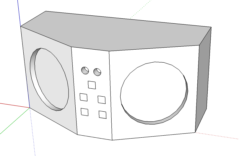
I realized using 1/4″ material wouldn’t give me much room to drive screws into, so I increased to 1/2″. I added speaker mounting holes and the lids were given holes where screws will hold the pieces together. The holes in the middle front section will be where LEDs and buttons go. The square hole in the back wall (which will probably be changed to a small circle and maybe moved to a side) is for the power cord.


bt-speaker-garage-v4-model.png
Version 4

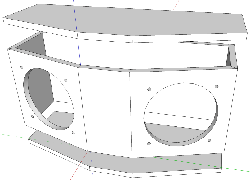
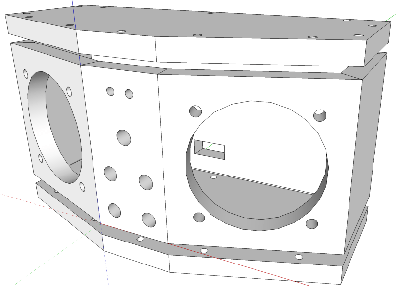
I realized if the lids were sitting on the top and bottom of the sides, you’d be able to see the ugly edges if I use something like plywood. So I increased the height of the walls and shrunk the lids to fit inside. There is a row of screw holes all the way around the top and bottom of the side walls, which will attach everything to the lids. I forgot about the on/off switch, so I added another hole on the front.

This is the first time I’ve attempted any 3D modeling and it’s been a lot of fun. Before I start working with wood, I’ll probably create a cardboard model to make sure the components fit inside. The dimensions are roughly 4.25″ deep, 9.5″ wide, and 5″ high.

All of the SketchUp files are in a bluetooth-speaker-design repo on GitHub if you want to use any of them.

Head over to Making a Bluetooth Speaker to see how the build turned out.

How To Cut A Picture Frame To Size Easily

Under the box lid of a Sears Craftsman 45° miter cut-n-clamp set, which was produced in the 1960s.

X + 2Y - 0.5 = L

  1. Measure the width of the picture. (X in inches)
  2. Measure the width of the molding. (Y in inches)
  3. 3 Add twice the molding width (2Y) to the picture size (X) then subtract 0.5.
  4. This will give you the length to cut your molding. (L in inches)

Then you can do the same thing for the opposite dimension if your picture isn’t a square.

Used Tools

I’ve been wanting to get more tools so I can do different projects with wood. It’s a lot cheaper to start out with used tools, especially as I learn. If I use certain tools a lot and find I need an upgrade, then I’ll fork over cash for new.

On a Saturday I hopped in the car and drove all over Saginaw looking for garage sales. There was no plan, other than to follow every sign I saw. I bought and bargained for a few things and then when I went home to eat lunch I found a big community garage sale about 25 minutes away. Off I went!

I probably hadn’t been to a garage sale in over 20 years. It was a lot of fun searching and it was interesting to see how different the items were from one house to the next. I was really hoping to find a table saw, band saw, and drill press, but no luck on any of the 3. I did make a good haul though.

The saw and miter box combo was brand new in the box, but most of the items needed some love. I sanded, stained, and waxed the wooden mallet and hammer handle. You can’t really see from this picture, but they both turned out great. The biggest tasks were taking apart the two sanders for a thorough cleaning because they were full of sawdust. I also disassembled the router but it wasn’t nearly as bad.

What gems have you found at garage sales?

5v Relay Module – Part 3

I had no plans for a part 3, but in part 2 of this series, I mentioned how I messed up the wiring several times when I was assembling the module. Instead of fixing it at the time, I started from scratch since I had extra parts. Well, I made some time to disassemble the non-working module and build a new one. I quickly set up a prototype on a breadboard to make sure I didn’t make the same mistakes and then I soldered it all together on a permanent board. Was smooth sailing, even with squeezing everything in as much as I could.

Now I have a two different spare relay modules, depending on power requirements, when I need one for a project.

Sound Card Oscilloscope

Earlier this year I came across an old Make post about building your own oscilloscope. I messed around with it a little bit at the time, but I didn’t have the necessary potentiometers, so I set it aside. Then the topic came up again when the tutorials accompanying HackerBox #0018 made use a 3.5mm audio breakout module and some PC oscope software. So in my next Digi-Key order, I got the pots I needed and I picked up some cheap test leads on Amazon. It’s several months later, but I got around to building my own sound card oscilloscope.

First, a couple of notes…

You’ll definitely want to read through the Make post to get familiar with the project. As mentioned in their guide, there really isn’t any good oscope software for the Mac like there is for the PC. With Audacity, which is what I used, at least you can see the signals in wave form.

I spliced an old audio cable. There are several different styles of 3.5mm connectors, but if you’re doing 2 channels, you’ll want to make sure you your cable has the tip, ring, and sleeve.

3.5mm-Male-Connections.png
Source: blog.audio-technica.com

A lot of MacBooks only do mono microphone input. Several Mac bummers in this build! It wasn’t easy, but I found a USB adapter on Amazon that does stereo mic input (most of them only do mono). It’s pricey at almost $30 for something I’m not even sure I’ll use after this build.

Enough of that, on to the build…

I added the LEDs to my build as a visual reference a signal was coming through, but they can be left out, just like in the Make build. If you’re interested in the Fritzing I showed in the video, head over to sound-card-oscilloscope on GitHub. Whenever I’m soldering up a final project I prefer to have the Fritzing for reference instead of looking at my prototype, which typically has a lot of extra wires hanging around. Having a nice clean diagram helps me from making mistakes.

I also found another guide on a site called Home DIY Electronics, which I didn’t end up following.

If you have any questions or build your own version of this, let me know in the comments.

Updates to Home Assistant Projects

My garage temp sensor, running home-assistant-temperature-monitor stopped working several months ago. I didn’t have time to figure it out and then summer hit, when it’s not important since I don’t heat up the garage before I workout. This weekend I finally got around to troubleshooting the problem.

Turned out I needed to install Adafruit_Python_GPIO. I must have updated my code at some point without fully testing, otherwise I’m not sure how any of it worked before. I didn’t investigate that though; I was more concerned with fixing it and doing some improvements. I updated the OS and everything on the Raspberry Pi since it hadn’t been turned on in quite some time.

Earlier this year, another Pi on my network, the one running Home Assistant and Pi-hole, ran out of disk space without warning. I’ve wanted to put in a notification system so it never happens again, so I updated home-assistant-pi to report the disk use % to HA. I added an automation to notify me whenever it’s above 90% for one of my Pis. I also reworked all of the automations in home-assistant-pi to make it easier to configure each time I get a new Pi.

img_9705

That all took much longer than I expected. Most of the trouble was trying to understand the Jinja template system used in HA and where it can be applied to configurations. I think I’m finally getting the hang of it.

While writing this post, I found an old draft with some other updates to home-assistant-pi I never published. Maybe I never finished and that’s why everything stopped working! Here’s a list of some previous updates:

  • Fixed errors causing program to crash.
  • It wasn’t reconnecting very well, especially if Home Assistant went away (ex. for a restart after an upgrade). Rewrote how the MQTT connection works.
  • Switch from PushBullet to iOS notifications.
  • Changed show/hide Home Assistant group automations.

Now that this stuff is running again and I have a better understanding of the Home Assistant automation capabilities, I need to continue the series of posts I planned on home automation. It’s been five and a half months since I published Part 1!

YI 4K Action Camera – Screen Replaced

The replacement came in for my shattered YI 4K Action Camera touchscreen. I was surprised it only took 10 days to get here from Shenzhen, China.

I followed this YouTube video, even though mine isn’t the newer 4K+ version of the camera. The only difference I noticed was the type of connector for the shutter.

I made one mistake, as you can see below, cracking the front cover above the lens. It won’t affect the performance, so not a big deal.

I wasn’t nearly as fast as the guy in the video, but I did it in less than an hour. Easy peasy compared to replacing the screen on an iPhone, which I will never attempt again.

Kacilia Tru-Align Body System

When I worked a booth at the National Wellness Conference a couple of months ago, I came across Kacilia at one of the other booths. The idea of this system/technique is to lay face down on a bunch of pads, which set the spine into a neutral position, and let gravity work. I tried it out for about 15 minutes while I was there and it felt really good. The inventor did an eval on my body positions before and after, which showed significant improvement. She claims to have had people reverse their spinal issues after several months of using this for 20 minutes a day. My issues come from a compressed L5 and she was confident her method could help me.

There was no way I was going to pay $400 for a fancy mat and some pads though. I figured I could create my own version. I already had 2 foam rollers, a yoga block, and a yoga mat. I purchased a few more items:

I bought this other stuff several weeks ago, but hadn’t used it yet. Yesterday I tweaked my back pretty bad again, so it’s time to try something new.


It may not work at all and I don’t know that I’ll use it daily, but it’s worth a shot. Having an excuse to take a 20 minute nap sounds pretty good too. Here’s a demo video of the actual system.

2017 Maker Faire Detroit

On Sunday I spent almost 6 hours at the Henry Ford Museum for Maker Faire Detroit. It was a great venue for it because attendees had access to the museum as well.

IMG_9631.jpg

Maker Faire is a gathering of fascinating, curious people who enjoy learning and who love sharing what they can do. From engineers to artists to scientists to crafters, Maker Faire is a venue for these “makers” to show hobbies, experiments, projects.

We call it the Greatest Show (& Tell) on Earth – a family-friendly showcase of invention, creativity, and resourcefulness.

Glimpse the future and get inspired!

Maker Faire Detroit

It was inspiring to see all of the makers and I had a blast geeking out.

Other posts about the event…

DIY Overhead Camera Rig

I’ve been recording more videos at my hobby desk and hanging a GoPro from my LED desk lamp via a Gorillapod wasn’t cutting it. Having to run GoPro’s Capture app on my iPhone connected over a WiFi network broadcast by the GoPro in order to see a preview of the camera view was also a pain point in my setup. I think I’ve even mentioned wanting to get a new camera in other posts.

My friend Casey was looking for a GoPro for his 5-year-old son, so it was perfect timing to get rid of my GoPro HERO3 Black Edition. I figured I’d just upgrade to the HERO5 Black, but it’s $400 for just the camera. After doing a little reading, I decided to get a YI 4K Action Camera with Selfie Stick, 2 spare batteries + charger, and an accessory kit. All of that ended up being $100+ cheaper than the GoPro HERO5 Black itself!

I had also been looking at a lot of videos and tutorials for building my own overhead camera rig. Then I remembered I had this lamp stashed away in a storage closet…

img_9566

I took the whole thing apart.

img_9567

I started putting things back together, using only the pieces I needed. I immediately noticed an issue. The swing arm would go up to about 20 degrees shy of vertical, but it wouldn’t go down more than this…

img_9568

I tried to get a decent picture showing how this joint works, but it’s hard to see in the photo below. There is a slot carved out of the edge and then a screw that hits the edges of the slot.

Here’s a better picture at just the notch…

img_9575

I needed to extend one side of the notch, which was quick work for my Dremel.

img_9576

After the adjustment, the arm can swing down to about 45 degrees.

The next problem I faced was needing some type of bracket where the light bulb used to be connected so I could attach the camera. I found this old ceiling light fixture bracket in my box of goodies. The threaded hole in the middle was a perfect match to the bolt on the end of the stand.

img_9573

I didn’t need the entire thing so I cut off one side with my Dremel.

img_9577

I found another part (the long arm type piece you see below) in my goodie box, which fit perfectly in the camera mount pieces. I had to use a couple of mount pieces from the accessory kit to get the camera oriented in the correct position relative to the stand. There was one trip to Home Depot for the wingnut, thumb screw, and small washers (definitely needed a few for spaces with the camera bracket at the bottom). Here is everything laid out before assembly.

Of course I had to test it out right away, especially since I hadn’t even turned on my new camera yet. I grabbed a couple of fidget spinners and adjusted the rig.

img_9579
I may need to create a cover or paint the base due to the reflection, which won’t be ideal for lighting.

Being able to frame the shot immediately with the camera LCD is amazing compared to the shit show I used to do with the GoPro.

Check out the video…

In case you weren’t keeping track, blue spun for 1:38 and black went 4:58!

Did you notice the shaking at the beginning of the video when I started up the spinners? Not good. I thought it would be super stable because the base of the stand is quite heavy (reminds me of the sand filled base of a moveable basketball hoop). Most of the movement seemed to be coming from the bracket I cut. An unused dead bolt bracket from my goodie box matched up well enough in size after making one of the holes bigger. This allowed me to double up the thickness, which does seem to help.

img_9581-1

I’ll have to do some testing while working on a project on the desk, because if this rig shakes the camera every time the desk moves a little bit it won’t be good.

As a bonus, there are some really useful parts of the lamp left. Maybe I can come up with a neat DIY lamp some day. The foot switch is also neat and could be used for a lot of things.

img_9572