5v Relay Module – Part 2

A couple of weeks ago I built a 5v relay module, but realized the relay wasn’t sufficient for my needs. So I had to order a heftier one that could handle more than 0.5 amps of current.

I was under a time crunch and couldn’t wait for a 5 or 10 pack, which had longer shipping times, so I had to go with a set of 2 for $5.99. These are basically the same relays used in all of the manufactured modules you can buy for less than $5, especially if you buy multiple units.

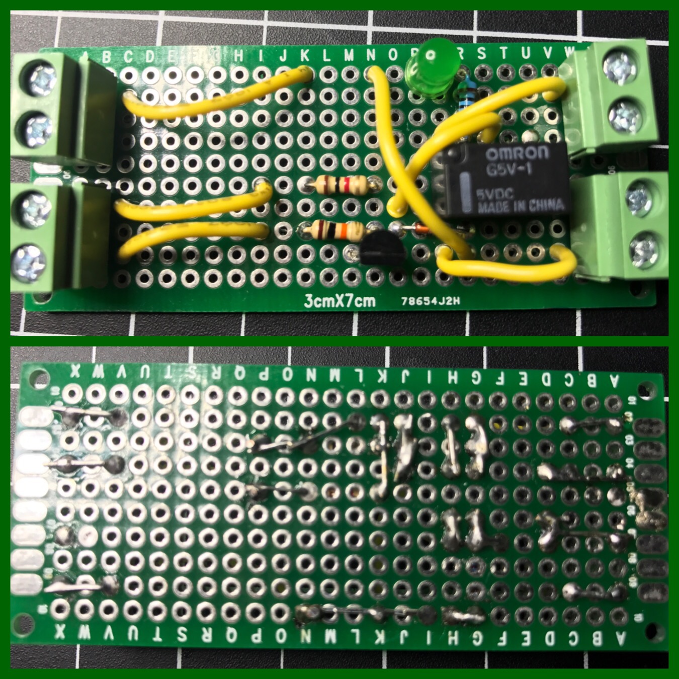
I set up my GoPro overhead and talked through the build process of my new relay module. It was not a smooth process, because I finally messed up my wiring, which I’d been so proud of hitting a 100% success rate on first attempts when putting together circuit boards. I not only messed up, but I realized my mistake, and then fucked it back up after thinking I was right the first time.

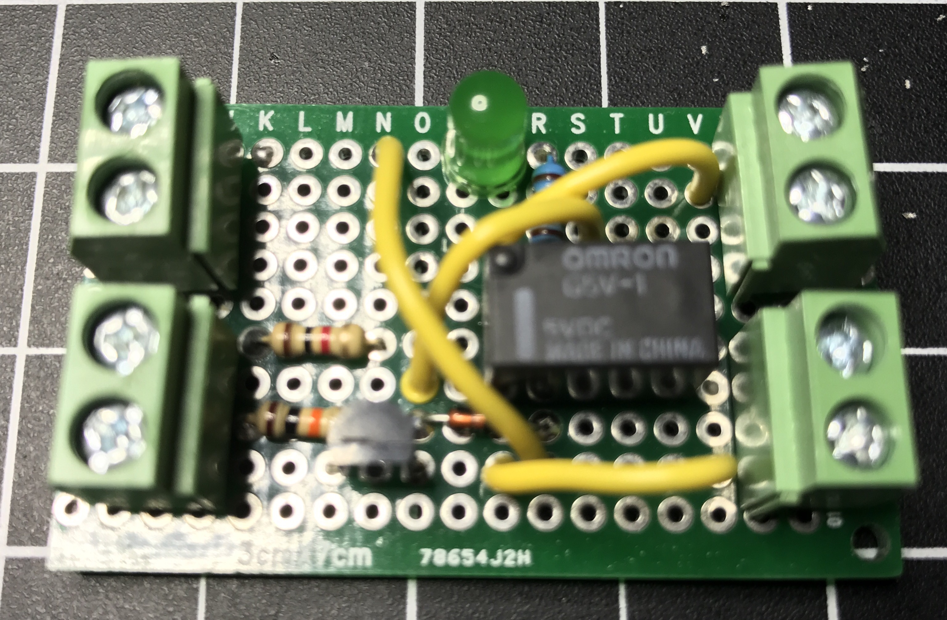
I forgot to take any good pictures of the completed relay module this time around, so here is a blurry screenshot I grabbed from the video, showing the original relay module, the non-working version (which I’ll eventually fix up), and my final version. Similar to whenever I screw up and lose a bunch of code, I made it a personal challenge to turn out my best work on the redo. As you can see, my final version saved a lot of space.

relays

Now that I’ve created my own relay modules, I won’t do it again unless I have specific requirements. Buying the same thing already made is a lot more time effective. It was fun and a great learning experience though. Here’s what the wiring diagram looks like spaced out on a breadboard. There isn’t much to it.

fritzing-relay-no-led

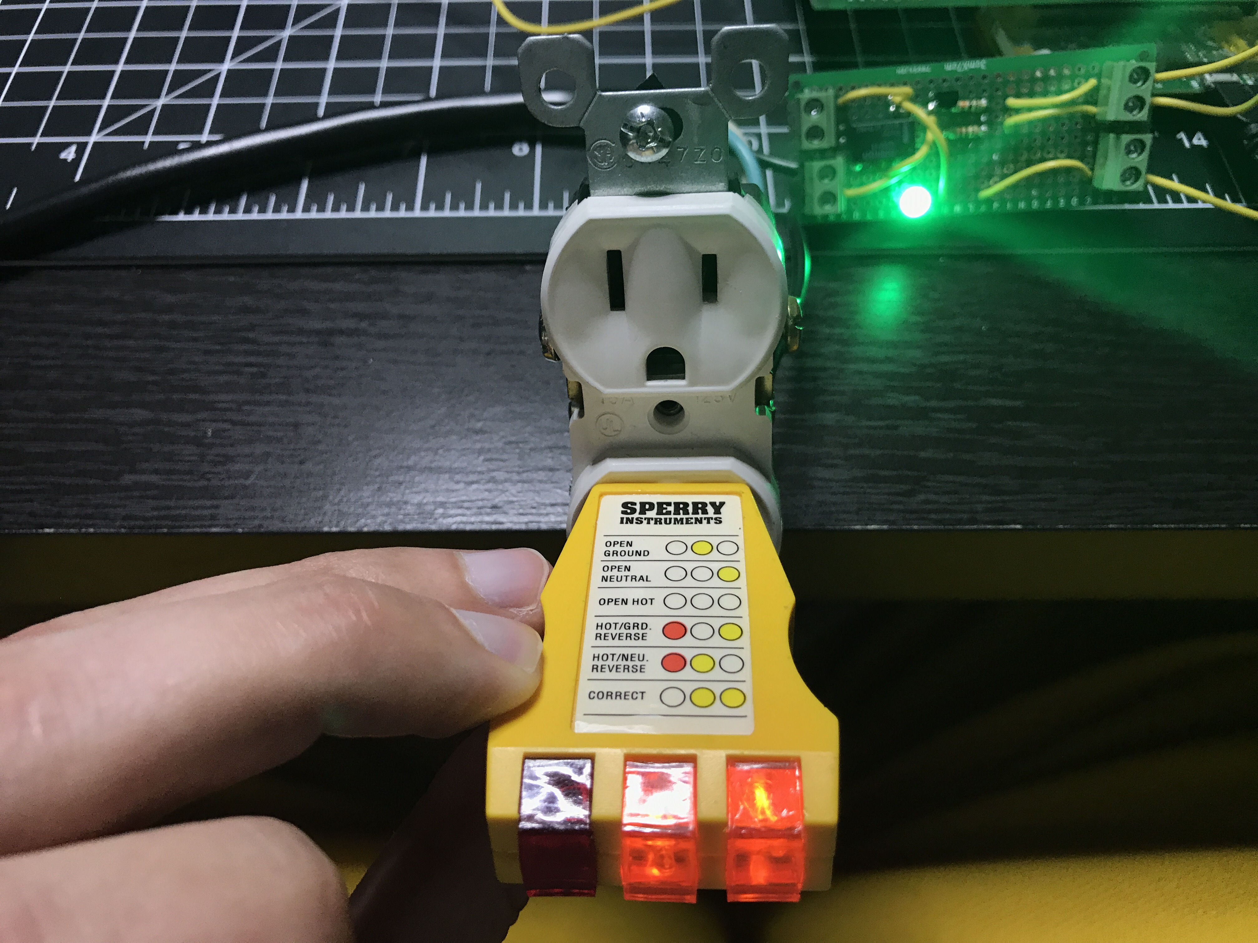
You can grab Fritzing files over on GitHub. Two things that helped me out a lot with this build were a video Homemade 5V Single Channel Relay Module Shield For Arduino, PIC, AVR and an article Turn Any Appliance into a Smart Device with an Arduino Controlled Power Outlet. Between finishing my build and writing this post, I also came across Arduino Controlled Power Outlet on Electronics Hub, which is a neat site with a lot of great circuits and tutorials.

There also ended up being a part 3 to this.

5V Relay Module – Part 1

You can buy all sorts of 5V relay modules on Amazon for as little as $3-4 (probably even less if you get really cheap). They even sell boards with multiple relays if you need to switch more than one thing. Since I had all of the necessary parts I built my own. Yesterday I finished the board, because I had to do something before National Week of Making ended.

It worked great switching power from a 9V battery, but the real test was hooking it up to mains power. Electricity gets a lot more dangerous at 120V! It was a little scary plugging everything in and flipping the input, especially after reading so many warnings online, but there were no sparks.

Tester shows the wiring is correct.

I need to pick up a plastic outlet box to house everything so it’s safer with the exposed soldered circuit board in there; I don’t know what I was thinking when I bought a metal one. I’ll publish a more detailed post this weekend when it’s complete.

Update: I realized the relay I used in this module can’t handle the amount of current I need, so I ordered a different type of relay and will be making a new module. I’ll take the opportunity to make a more compact design as well. I did shrink this one a bit and cut off some of the board. I’ll save this module in case I ever need it for a project.

Check out Part 2.

A Raspberry Pi HAT

I successfully built the second piece to a large project I’m working on. I’ve essentially built my own XL Raspberry Pi HAT (Hardware Attached on Top). Since I’m not following the specs, I shouldn’t really call it a HAT.

I’m not sure how, but once again I correctly connected everything on the first try. Either I’m extremely lucky, my attention to detail is paying off, or a combination of the two. I’m just waiting for some catastrophic failure to happen soon when I solder things the wrong way one of these days. Every one of my solder bridges worked. I did run continuity tests on all of the early bridges, which I’m sure was a big factor to my success.

Any guesses on what this board does? Leave your best guess in the comments. It’ll be at least a month before I share more details because I need to finish the entire project first.

Solder Bridges

Yesterday I posted about multiplexing 7 segment displays, but it’s actually been weeks since I got that circuit working. After 2 weeks of travel and a busy weekend, I finally got some time on Wednesday night to start moving the circuit from the breadboard to a more permanent home. I stocked up on a variety of different sized circuit boards, but unlike a breadboard each hole on these is independent. It was time to learn how to make solder bridges. After fumbling through about 10 bridges I started to get the hang of it. They won’t win any beauty contests, but they’re functional, which is what matters.

img_9368

In round 2 last night I tried a couple of tricks. The first method is using a small wire or the discarded end of a lead (this happened to come from trimming off the ends of a resistor) to bridge pads together.

img_9372
These will be connected to ground.

Another trick is to bend over the ends of leads to create a bridge. In the left and right columns you can see this type of bridge used. The middle column shows bent leads I’ll use when I connect more wires.

img_9373

Both methods worked a lot better than trying to use mountains of solder to jump the connection pads.

By the way, I find soldering (no matter what it’s for) to be extremely relaxing. Maybe it’s something to do with the order of the entire process; physically connecting things to make a circuit work. I typically do it late at night with some music and a cold beer.

I’m glad I decided to upgrade my soldering iron, by getting a Hakko FX888D. It works much better than the entry-level iron I’ve been using.