I flipped through and it covers everything you need to know about indoor rowing including setting up the rower for your body type, technique tips, 14 week training plans, and of course workouts, which are organized by skill level, training goals, time, and difficulty.
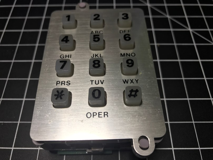
I’ve been on a kick tearing apart electronics. In addition to the switch I got a bunch of parts from, I’ve tore into a lamp and some old computer speakers. When I found an old telephone (it has a date of 5/30/1980 printed on it!) in my basement I knew I had to see what was inside. The previous owners left it in a storage room and I have no idea why I never pitched it. I didn’t take a picture before taking a screwdriver to it, but it looked exactly like the photo on the right.
People have been hacking phones for a long time. Perhaps the earliest and most well-known was the Steves (Jobs and Wozniak) using a blue box on payphones. I’m nowhere near that level, but you have to start somewhere right? I pulled the ringer, speaker, and microphone out of it. I haven’t messed with these yet.
A lot of parts were extremely dirty.
The part I thought would be neat to work with was this keypad.
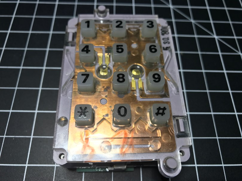
With the faceplate removed you can see the date stamp in the upper right.Back side.
It was a bit of a process figuring out how to tap into this thing. Eventually I realized what these contact switches on the sides were for.
There are seven of them. The top has two and the bottom has one, which correspond to the 3 columns of keys on the grid. Then the left and right sides each have 2, which match up with the 4 rows of keys.
I figured out I could solder wires to the contacts points connected to each of those switches. I was in! From the way the keypad was connected to the rest of the phones circuitry I knew the screws were an important piece to tie it all back into the entire system. After some trial and error I determined which screws should be used for power (red wire) and ground (black) in order to get useable data out of the 7 switch contact points. The other 3 screws also connect to power. I was using alligator clips on those, but disconnected them for the picture.
Something isn’t quite right about the screw connections though. When I connect them the opposite way, flopping to have 1 power and 4 grounds, the backlight on the keypad works, but the readings from the soldered contact points are useless. With them connected this way, I don’t get the backlight, but I get data I can make sense of. There is probably something obvious I’m missing about how this all works together.
Unfortunately for me, the output from the contact points isn’t digital (limited to on/off), so I couldn’t use the Arduino library. It would have made things so much easier. It’s not surprising though, since this piece of technology is almost 40 years old!
I was able to get some code mostly working. Detecting the column of a button press was pretty straight forward and works great. Rows detection is another story. I’m reading in analog values and using sampling along with standard deviations to determine which row’s value is unlike the others. Well, the first row always reads a pretty high value, when a key on any row is pressed. The values for the other rows fluctuate as expected. When that first row is high, I’ve attempted to also look for a high value from another row, but it triggers the wrong row too often.
Demo time…
Even making this short little video, which took at least 5 takes, there was a false trigger for pressing 1 and many key presses not being recognized. Not useable.
I have a hunch the screw connections are responsible, at least in some part, for sending DTMF signals, also known as Touch-Tone. I don’t really care to get in the business of decoding these. This is precisely why I was hoping I could detect useful output from each of the row and column contact points.
I pulled apart the unit even more and discovered a Western Electric 557D is the brains of the operation, but it’s so old there doesn’t seem to be a datasheet online for it. What I’m going to do is remove the PCB and wire up everything on my own. Then I can easily get on/off as digital values from the columns and rows and make sure the backlight works. Stay tuned…
Instagram and Insecurity Netflix will be releasing a true crime series about this young nun’s unsolved murder We Need More Repair Cafés Tesla driver says Model S ‘saved his life’ after walking away unscathed from a crash ~500-ft down a hill Love & breadsticks: There was a knife fight at Olive Garden Giving Credit Where […]
McDonald’s has the strawberry & crème pie back on the menu. These things are amazing! I stopped for a couple after picking up pizza slices for lunch. After putting in my order, the guy working the drive-thru asked, “Would you like to add a free cookie today?” They say there is no such thing as a stupid question.
Every time I update an SVN external to a new tagged release I have to look up this damn command. I have it saved in a Bear note containing SVN tricks. Finally added an alias to .bashrc on my work sandbox.
The battery (CR2450) in my garage door sensor was getting low, so I replaced it. I’ll keep the old one in my electronics kit for LED testing, as shown in this video. Touch the longer leg (anode) of the LED to + and the shorter leg (cathode) to –. Usually + is the top of the battery where the words are. Don’t worry, you won’t hurt the LED if you connect it the wrong way.
After tweaking my back and starting a push-only program which has a lot of accessory movements, I’ve been all about unilateral movements. Constantly using the barbell for lifting can create a lot of imbalances. One of the movements we do a lot is a Farmers Carry with kettlebells or dumbbells. Options get limited if you want to go heavier […]
Remember last week’s post about tearing apart a component switch to repurpose parts? I spent some time fooling around with IR after that. I thought it would be neat to recreate the basic functionality of switching between 3 devices. For my proof of concept the devices were simple the 3 status LEDs, but you can imagine the possibilities of turning on different devices or triggering processes run on a computer.
The new microcontroller I got is one I posted about a few months ago, called Puck.js. It has an IR transmitter built-in, so I wanted to use it to mimic a remote. Puck.js is pretty slick. It’s really neat being able to program a device in Javascript through a web IDE over Bluetooth Low Energy. No wires at all!
Propping a component into the GPIO pins like the author did doesn’t work for shit. You can’t get a solid electrical connection, especially if you bump it at all.
I kept getting Out of Memory errors on the device because the array would get really large really soon.
My next thought was to wire up to one of my other microcontroller that run Arduino, but the popular IR Library (IRLib2) doesn’t support the chips used in any of the boards I have. So over to a Raspberry Pi Zero. Pretty much every search result mentioned using Linux Infrared Remote Control (LIRC). May of the setup instructions I found were incomplete, but I was able to get things running by taking pieces from these two sites:
I’ll detail the steps that worked for me. Before I go down the software route though, I wanted to make sure the IR sensor worked. The only markings on the component are “71M4” and I have been unable to find a datasheet anywhere to match. Luckily these IR receivers are pretty standard and I had a pretty good idea of the pins from looking at how it was connected in the old device. I got the idea of hooking up a simple LED test circuit on the data pin from an Adafruit learn guide. Pin 1 is data, going into a GPIO pin on the Raspberry Pi (26 in my case), pin 2 is ground, and pin 3 is power (VCC). You may want to use the 3.3V pin on the Pi to provide your power instead of 5V just to be safe, or consult the datasheet for the IR sensor you’re using. Connect the anode of the LED to power and the cathode to pin 1 of the sensor using a 220 Ω (I used 200) resistor. When you press buttons on an IR remote, the sensor will send data through pin 1 and the LED will light up. Here’s a Fritzing wiring diagram for this test as well.
My test was successful! Now I was able to move on with some confidence knowing the part worked.
Install LIRC:
sudo apt-get update
sudo apt-get install lirc
Edit the /etc/modules file:
sudo nano /etc/modules
Add to the end:
lirc_dev
lirc_rpi gpio_in_pin=26
Change the pin if you’re using something other than 26. If you’re also going to do IR transmitting, you can add a space and gpio_in_pin=22 on that last line.
Press Ctrl + X, hit Y to say you want to save, and then Enter.
Edit the /etc/lirc/hardware.conf file:
sudo nano /etc/lirc/hardware.conf
Look for the DRIVER, DEVICE, and MODULES settings. Set them to match:
Press Ctrl + X, hit Y to say you want to save, and then Enter.
Edit your /boot/config.txt file:
sudo nano /boot/config.txt
Look for this line:
# Uncomment this to enable the lirc-rpi module
If you see it, remove the # from the next line and edit it to look like this (if your file doesn’t have it, add this to the end of the file):
dtoverlay=lirc-rpi,gpio_in_pin=26
If you’re going to do transmitting, also add this to the same line:
,gpio_out_pin=22
Change both pins to match whatever you’re using. Press Ctrl + X, hit Y to say you want to save, and then Enter.
Reboot your Pi:
sudo reboot
Now it’s time to use LIRC to record the codes sent by whatever remote you’re using. First you’ll want to see names you want to give your buttons. Run:
irrecord --list-namespace
Scroll through the list and make notes on all of the codes you want to use for your buttons. You’ll need the codes in a bit. Here was my list:
KEY_POWER
KEY_1
KEY_2
KEY_3
Stop LIRC:
sudo /etc/init.d/lirc stop
Use irrecord to create a configuration file for your remote. Follow the instructions carefully that come up on your screen. This took me several minutes for my remote with only 4 buttons.
Note: When it says Please enter the name for the next button (press to finish recording) is when you’ll need those codes above.
irrecord -d /dev/lirc0 ~/lircd.conf
When finished you’ll have a new file in your home directory. Take a look at it:
cat ~/lircd.conf
Mine looked like:
begin remote

  name  /home/pi/lircd.conf
  bits           16
  flags SPACE_ENC|CONST_LENGTH
  eps            30
  aeps          100

  header       9004  4474
  one           580  1666
  zero          580   542
  ptrail        578
  repeat       9006  2229
  pre_data_bits   16
  pre_data       0x61D6
  gap          107888
  toggle_bit_mask 0x0

      begin codes
          KEY_POWER                0x7887
          KEY_1                    0x40BF
          KEY_2                    0x609F
          KEY_3                    0x10EF
      end codes

end remote
Make a backup of the default LIRC configuration file:
You need to set up each button similar to what mine looks like:
begin
  remote = *
  button = KEY_POWER
  prog = pylirc
  config = KEY_POWER
end

begin
  remote = *
  button = KEY_1
  prog = pylirc
  config = KEY_1
end

begin
  remote = *
  button = KEY_2
  prog = pylirc
  config = KEY_2
end

begin
  remote = *
  button = KEY_3
  prog = pylirc
  config = KEY_3
end
Do a simple copy/paste and change the button and config for each entry.
Press Ctrl + X, hit Y to say you want to save, and then Enter.
Create a basic Python test program:
nano pylirc-test.py
Paste in:
#!/usr/bin/python

import pylirc

pylirc.init( 'pylirc', './pylirc.conf', 0 )

while ( True ) :
	s = pylirc.nextcode( 1 )
	command = None
	if ( s ) :
		for ( code ) in s :
			print( code["config"] )
Press Ctrl + X, hit Y to say you want to save, and then Enter.
Run the program:
python pylirc-test.py
Press buttons on your remote and if everything is working you’ll see the special name codes being output for each button you press.
Hit Ctrl + C to stop the program.
I already had all of the logic written for the buttons to work and switch LEDs, so it was easy to add in a little more code to take action when the appropriate IR codes were received.
Once I found the correct information, setup on the Pi was quite easy. A lot of steps, but easy stuff. Making the Puck.js duplicate my Infrared remote’s codes was a bit of a challenge. From the Puck.js Infrared tutorial I linked at the beginning I knew I needed to have an array of pulse lengths, but I didn’t have anything like that from the LIRC configuration. All I had was some hex values for each code:
KEY_POWER: 0x7887
KEY_1: 0x40BF
KEY_2: 0x609F
KEY_3: 0x10EF
Combined with another hex code for pre_data (0x61D6) from the lircd.conf file, I had more complete codes:
Infrared remote control signals from the LIRC remote configurations project, converted to Pronto Hex and Protocol, Device, Subdevice, and Function using lirc2xml…
BINGO! It had the Pronto Hex codes. I cloned the repo and started searching for my hex values. I found power, 1, and 2 matched up with codes used by something called a gigabyte TV. I plugged the codes into a program and they worked! I was only missed the code for button 3.
Then I spend way too much time still searching around. I knew enough about how IR worked and had 3 codes. I finally realized I should be able to figure out what changes to make in order to get my 4th and final code. I converted the hex values to binary:
KEY_POWER: 0x7887 = 111100010000111
KEY_1: 0x40BF = 100000010111111
KEY_2: 0x609F = 110000010011111
KEY_3: 0x10EF = 001000011101111
Then I started looking at the end of each array of Pronto Hex codes, because every code uses the same pre_data. I quickly determined an ON bit (1) was 003e, OFF (0) was 0013, and they were separated by 0017. I made the necessary adjustments and had all 4 buttons working with IR!
This IR journey turned out to be quite an adventure. I learned a lot, which was the point. My infrared-3-input-selector project on GitHub has the Python program used in the demo video, my pylirc config file, the simple pylinc test program, the Puck.js code, and even an Arduino sketch with the button and LED logic I created initially before realizing I needed to switch to the Raspberry Pi.

 I’ve been on a kick tearing apart electronics. In addition to


 There are seven of them. The top has two and the bottom has one, which correspond to the 3 columns of keys on the grid. Then the left and right sides each have 2, which match up with the 4 rows of keys.


 I got
I got 

